Kuppan T. Heat Exchanger Design Handbook
Подождите немного. Документ загружается.

284
Chapter
5
2.
Calculate the ideal heat transfer coefficient
h,
given by
where
j,
and
($Jn
are defined next.
The term
j,
is the ideal Coulburn
j
factor for the shell side and can
be
determined from
the
appropriate Bell-Delaware curve for the tube layout and pitch and a typical curve.
For
example,
d
=
0.75 in (19.05 mm), pitch
=
1.0 in (25.4 mm), and
8,,
=
30°, curve fits for
j,
are
given by Bell
[40]:
j,
=
1.73Re:4694’
1
S
Re,
<
100
=
0.7 17Re
”‘)
100
I
Re,
<
1000
=
0.236Re
‘,“
M’
loo0
5
Re,
The term
($Jn
is the viscosity correction factor, which accounts for the viscosity gradient
at the tube wall versus the viscosity at the bulk mean temperature of the fluid, and is given by
[48]:
For liquids,
$,
is greater than
1
if the shell-side fluid is heated, and
less than
1
for shell-side
fluid is cooled. In order to determine
p,,
it
is
essential to determine
T,,
which is estimated as
follows using the approximate values of
h,
and
h,
[48]:
-
T,,
T,,
=
T,,,,
+
T
1
+
h,h,
(55)
where
T,+
and
T,,,
denote the average mean metal temperatures
of
shell and tube, both of
them being the arithmetic means of inlet and outlet fluid temperatures on the shell side and
tube side, respectively, An accurate equation to calculate tube mean metal temperature is given
by TEMA [3]. For gases, the viscosity is a weak function of temperature. The correction factor
o\
is
formulated as follows
For gases being cooled:
(@J”
=
1.0
(56)
+
273.15)
0.25
For gases being heated:
(z,o,,
1
(57)
For a gas being heated,
T,
is always higher than
Th,ak
and hence the correction factor is less
than 1
.O.
Calculate the shell-side heat-transfer coefficient, given by
h,
=
h,
J,
JI J,
Jb
J,
(58)
Shell-Side Pressure Drop. The shell-side pressure drop is calculated in the Delaware
method by summing the pressure drop for the inlet and exit sections, and the internal sections
after applying various correction factors. The total shell-side pressure drop
Ap,
consists of the
pressure drop due to
(1)
crossflow
Ap,,
(2) window regions
Ap,,
and
(3)
entrance and exit
sections
Ape
as given by Refs. 39 and 40:
285
Shell and Tube Heat Exchanger Design
Aps
=
APC
-k
APW
+
Ape
(59)
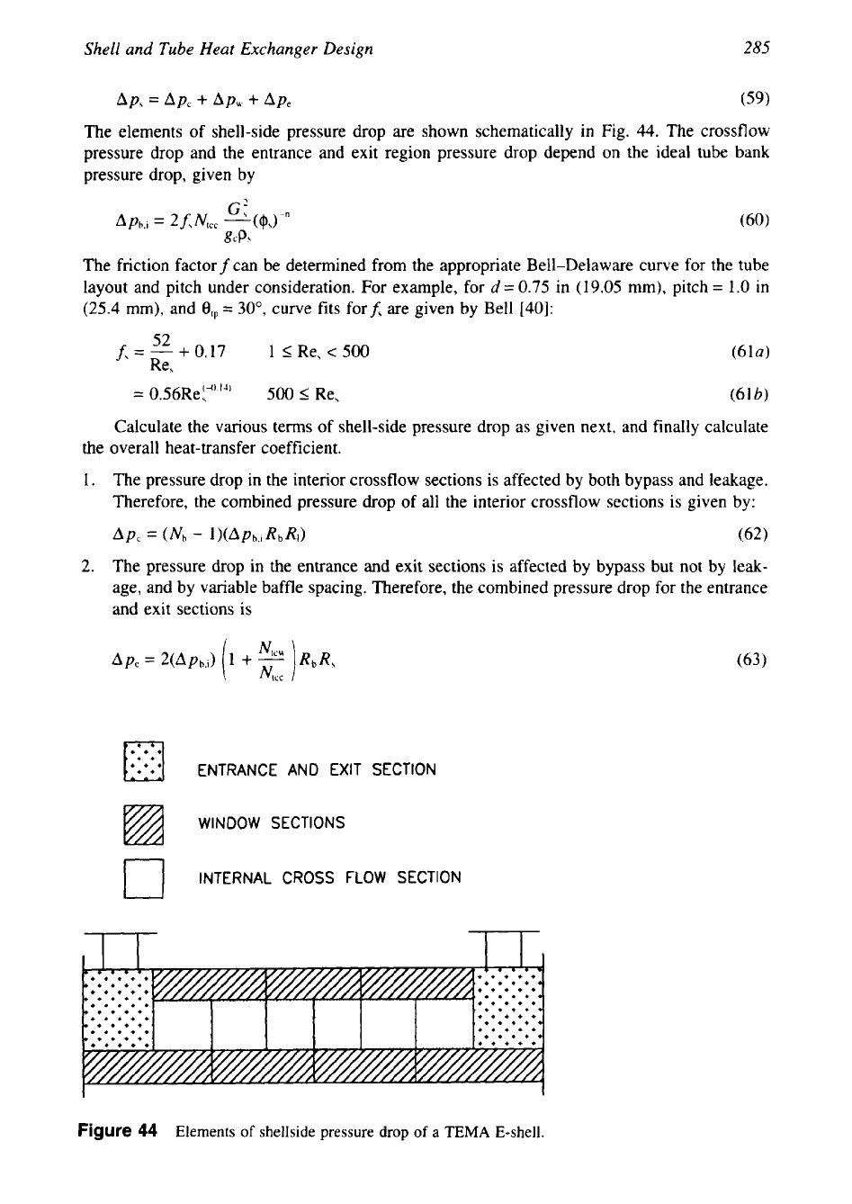
The elements of shell-side pressure drop are shown schematically in Fig.
44.
The crossflow
pressure drop and the entrance and exit region pressure drop depend on the ideal tube bank
pressure drop, given by
The friction factor
f
can be determined from the appropriate Bell-Delaware curve for the tube
layout and pitch under consideration. For example, for
d
=
0.75 in
(19.05
mm), pitch
=
1
.O
in
(25.4
mm), and
0,,
=
30°, curve fits forf, are given by Bell
1401:
c3
JL
f,=-+0.17 1 IRe,<500
Re,
Calculate the various terms of shell-side pressure drop as given next, and finally calculate
the overall heat-transfer coefficient.
1.
The pressure drop in the interior crossflow sections is affected by both bypass and leakage.
Therefore, the combined pressure drop
of
all the interior crossflow sections
is
given by:
Ap,
=
(Nh
-
l)(Aph,i
Rh
RI)
(62)
2.
The pressure drop in the entrance and exit sections is affected by bypass but not by leak-
age, and by variable baffle spacing. Therefore, the combined pressure drop for the entrance
and exit sections is
ENTRANCE AND EXIT SECTION
Figure
44
Elements
of
shellside pressure
drop
of
a
TEMA E-shell.
286
Chapter
5
3.
The pressure drop in the windows is affected by leakage but not by bypass. Therefore, the
combined pressure drop of all the window sections is given by
APWNbRI
(64)
where
Apu
is given as follows:
For Re,
2
100,
(2
+
0.6NlcU)G~
Apu
=
2gcp,
For Re,
<
100,
in
which the window mass velocity
G,
is given by
Summing these individual effects, we obtain the equation for the total nozzle-to-nozzle
shell-side pressure drop:
The total shell-side pressure drop of a typical shell and tube exchanger is
of
the order of
20-30%
of the pressure drop that would be calculated for flow through the corresponding heat
exchanger without baffle leakage and without tube bundle bypass effects
[39].
Tube-Side Heat-Transfer Coeflcient and Pressure
Drop.
Tube-Side Heat-Transfer Coefficient.
1.
Calculate the tube-side mass velocity
G,,
Reynolds number Re,, and Prandtl number, Pr,:
M,
G,
=
-
for single pass
A,
--
A41
-
for
N,
passes
Amp
where
7c
A,
=
-
dZN,
4
and where
A,
is
the tube-side flow area,
Np
the number
of
tube-side passes,
NI
the number
of tubes, and
2.
Calculate the tube-side heat-transfer coefficient,
11:
For lamina flow with Re, of
2100
and
less, the heat-transfer coefficient is determined from the Sider-Tate
(1936)
empirical equa-
tion for both heating and cooling of viscous liquids:
287
Shell
and
Tube
Heat
Exchanger Design
For those cases where the Grashof number
Nu,
exceeds 25,000 the value of
h
obtained from
Eq. (71) must be corrected for the increase in heat transfer due to natural convection effects
by multiplying by the term
0.8(
1
+
0.015Na~") (714
where
p
=
thermal coefficient of cubical expansion, 1/"F;
Ar
=
temperature difference,
OF;
Nu,
=
Grashof number; p,
=
tubeside fluid density, lb/ft3;
g,
=
acceleration of gravity, 4.17
x
10'
ft/
hr';
pt
=
viscosity at bulk mean temperature, lb/hr.ft.
At values above 10,000 turbulent flow occurs and the heat transfer coefficient is determined
from the following correlation:
Sider-Tate equation modified by McAdams:
In the intermediate region where Reynolds number varies from 2100 to 10,000 the relation
does not follow a straight line. Fig.
45
can be used to find the tube side heat transfer coefficient
using Sider-Tate relation.
Colburn equation:
Dittus-Boelter equation
=
0.023Rey' Pry
k,
where
n
=
0.4
for heating
=
0.3 for cooling
In the intermediate region where Re, varies between 2100 and 10,000, the relation does
not follow a straight line.
In
this region, Kern [40] recommends the following formula:
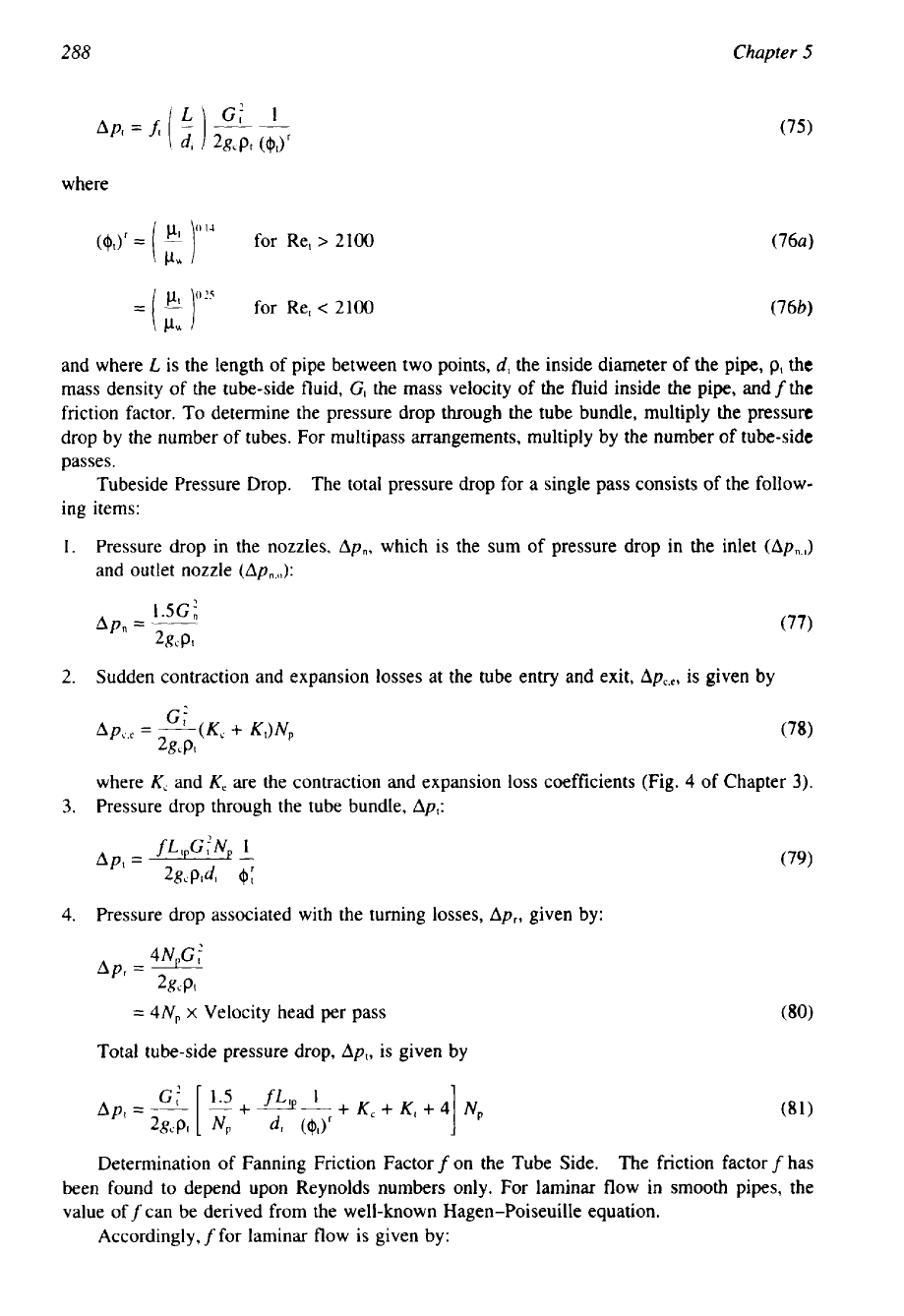
Pressure Drop in Tubes and Pipes-General. For tubes and pipes, the pressure drop in
steady flow between any two points may
be
expressed by the following Weisbach-Darcy
equation:
288
Chapter
5
where
for Re,
>
2
100
and where
L
is the length of pipe between two points,
d,
the inside diameter of the pipe,
p,
the
mass density of the tube-side fluid,
G,
the mass velocity of the fluid inside the pipe,
and
f
the
friction factor. To determine the pressure drop through the tube bundle, multiply the pressure
drop by the number of tubes. For multipass arrangements, multiply by the number
of
tube-side
passes.
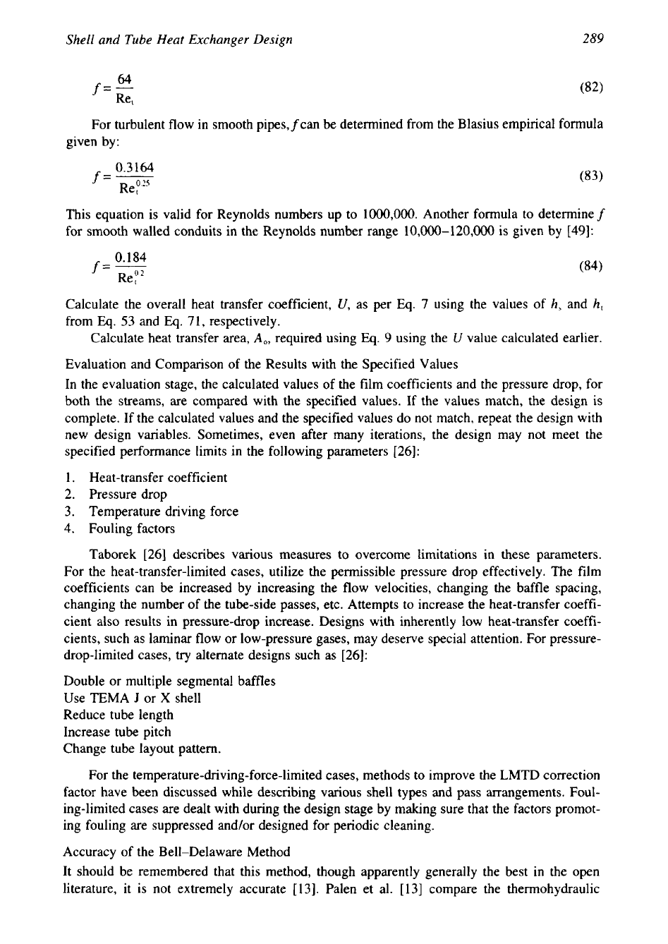
Tubeside Pressure Drop.
The total pressure drop for a single pass consists
of
the follow-
ing items:
Pressure drop in the nozzles,
Ap,,
which is the sum of pressure drop in the inlet
(Ap,,.,)
and outlet nozzle
(Apn.J:
Sudden contraction and expansion losses at the tube entry and exit,
AP~,~,
is given by
where
K,
and
K,
are the contraction and expansion
loss
coefficients (Fig.
4
of Chapter
3).
Pressure drop through the tube bundle,
Ap,:
Pressure drop associated with the turning losses,
Apr,
given by:
4N,Gt
Apr
=
2gcp,
=
4Np
x
Velocity head per pass
Total tube-side pressure drop,
Ap,,
is given by
Determination of Fanning Friction Factor
f
on the Tube Side.
The friction factor
f
has
been found to depend upon Reynolds numbers only. For laminar flow in smooth pipes, the
value off can be derived from the well-known Hagen-Poiseuille equation.
Accordingly,
f
for laminar flow is given by:
289
0.3164
Shell and
Tube
Heat
Exchanger Design
f=-
64
Re,
For turbulent flow in smooth pipes,fcan be determined from the Blasius empirical formula
given by:
f=-----
Re
PZS
This equation is valid for Reynolds numbers up to 1000,000. Another formula to determine
f
for smooth walled conduits in the Reynolds number range 10,000-120,000 is given by [49]:
0.184
f=--
(84)
Rep"
Calculate the overall heat transfer coefficient,
U,
as per
Eq.
7 using the values of
h,
and
h,
from
Eq.
53
and
Eq.
71, respectively.
Calculate heat transfer area,
A,,
required using Eq.
9
using the
U
value calculated earlier.
Evaluation and Comparison of the Results with the Specified Values
In the evaluation stage, the calculated values of the film coefficients and the pressure drop, for
both the streams, are compared with the specified values. If the values match, the design
is
complete. If the calculated values and the specified values do not match, repeat the design with
new design variables. Sometimes, even after many iterations, the design may not meet the
specified performance limits in the following parameters [26]:
1.
Heat-transfer coefficient
2.
Pressure drop
3.
Temperature driving force
4.
Fouling factors
Taborek [26] describes various measures to overcome limitations
in these parameters.
For
the heat-transfer-limited cases, utilize the permissible pressure drop effectively. The film
coefficients can be increased by increasing the flow velocities, changing the baffle spacing,
changing the number of the tube-side passes, etc. Attempts to increase the heat-transfer coeffi-
cient also results in pressure-drop increase. Designs with inherently low heat-transfer coeffi-
cients, such as laminar flow or low-pressure gases, may deserve special attention. For pressure-
drop-limited cases,
try
alternate designs such as [26]:
Double or multiple segmental baffles
Use TEMA
J
or
X
shell
Reduce tube length
Increase tube pitch
Change tube layout pattern.
For the
temperature-driving-force-limited
cases, methods to improve the LMTD correction
factor have been discussed while describing various shell types and pass arrangements. Foul-
ing-limited cases are dealt with during the design stage by making sure that the factors promot-
ing fouling are suppressed and/or designed for periodic cleaning.
Accuracy
of
the Bell-Delaware Method
It should be remembered that this method, though apparently generally the best in the open
literature, it is not extremely accurate [13]. Palen et al.
[13]
compare the thermohydraulic
290
Chapter
5
performance prediction error of Bell-Delaware methods [38,39], stream analysis methods
[
131,
and Tinker [37].
Extension of the Delaware Method to Other Geometries
The Delaware method, as originally developed and as it exists in the open literature, is more
or less explicitly confined to the design
of
fully tubed
E
shell configurations using plain tubes.
Extension of this method to other geometries are discussed in Refs. 15 and 27, and these are
discussed in this subsection.
Applications to Low-Finned Tubes.
It is possible to apply the Delaware method to the design
of such heat exchangers in a fairly straightforward way by making use of the results of Brigs
and Young
[50]
and Briggs, Katz, and Young [51].
As
shown by Briggs et al. [51], the Colburn
j
factor for low-finned tubes is slightly less than for a plain tube in the Reynolds number range
about 2-1000; the difference is larger in the lower Reynolds number range. The fin-tube
j
factor
j,
can be represented in terms of plain-tube-bankj factor asj, as [15]:
jl
=
Ktj,
(85)
where
K,
is the correction factor whose values, taken from Ref.
50,
are presented in Ref. 15.
Its approximate values at discrete points are:
Re
20
70
loo
200 400 600 800-1000
K,
0.575 0.65 0.675 0.75
0.885
0.975 1
.o
For the
fin
tube friction factor, Bell [39,40] suggests a conservative value that is 1.5 times
those for the corresponding plain tube bank, whereas Taborek
[
151 recommends 1.4 times
the
friction factor of the plain tube bank. The adaptation of the Bell-Delaware method to finned
tubes
is
explained
in
Refs. 15 and 27.
Application to the No-Tubes-in- Window Configuration.
In calculations, use
N,,
=
0
and the
baffle configuration correction factor
J,
=
1. Otherwise the calculation is essentially identical
to a fully tubed bundle. It is suggested that one choose a smaller baffle cut
so
that the free flow
area through the window corresponds reasonably closely to the free crossflow area through the
tube bank itself.
Application to
F
Shells.
Since the shell side is essentially split in two, it is possible to adopt
the Delaware method by reducing all of the areas for flow by half compared to the case for a
single shell side pass.
It
is assumed that the flow leakage and conduction across the longitudinal
baffle are minimized.
Application to
J
Shells.
The adaptation of the method to a
J
shell is straightforward. Take
one-half the length of the exchanger as a “unit” equivalent to an
E
shell and take one-half the
mass flow rate.
Application to Double Segmental and Disk and Doughnut Exchangers.
According to Taborek
[
151, the Bell-Delaware method cannot be easily adapted to these baffle types, as the driving
forces for bypass and leakage flow are much smaller than for segmental baffles.
APPENDIX
1
Al.l
Reference Crossflow Velocity
as
per Tinker
[37]
Reference crossflow velocity as per Tinker is given by:
291
1
Shell and Tube Heat Exchanger Design
where
A,
is the crossflow area within the limits of the tube bundle,
Fh
is the fraction of total
fluid flowing through
A,
of clean unit,
M
is the
A,
multiplication factor,
M,
is the mass flow
rate of shell-side fluid, and
p,
is the mass density of shell-side fluid.
A,
=
axLbcD3
(87)
Fh
=
1
+
Nhfi
I
M=
The list of expressions required to evaluate
Nh,
M,
are
Di
a,
=
-
D3
For units with sealing strips,
ui
is
given by
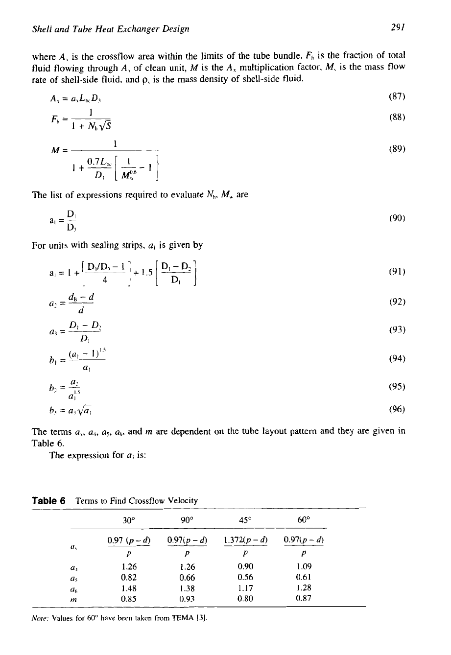
The terms
a,,
a4,
u5,
a6,
and
rn
are dependent
on
the tube layout pattern and they are given in
Table 6.
The expression for
a7
is:
Table
6
Terms
to
Find Crossflow Velocity
30" 90" 45O 60"
0.97 (p
-
d)
0.97(p
-
6)
1.372(p
-
d)
0.97(p
-
6)
a,
P
P
P
P
U?
1.26
1.26 0.90
1.09
a
0.82
0.66
0.56
0.6
1
at,
1.48
1.38
1.17
1.28
m
0.85
0.93
0.80
0.87
Nore:
Values
for
60"
have
been
taken
from
TEMA
[3].
292
Chapter
5
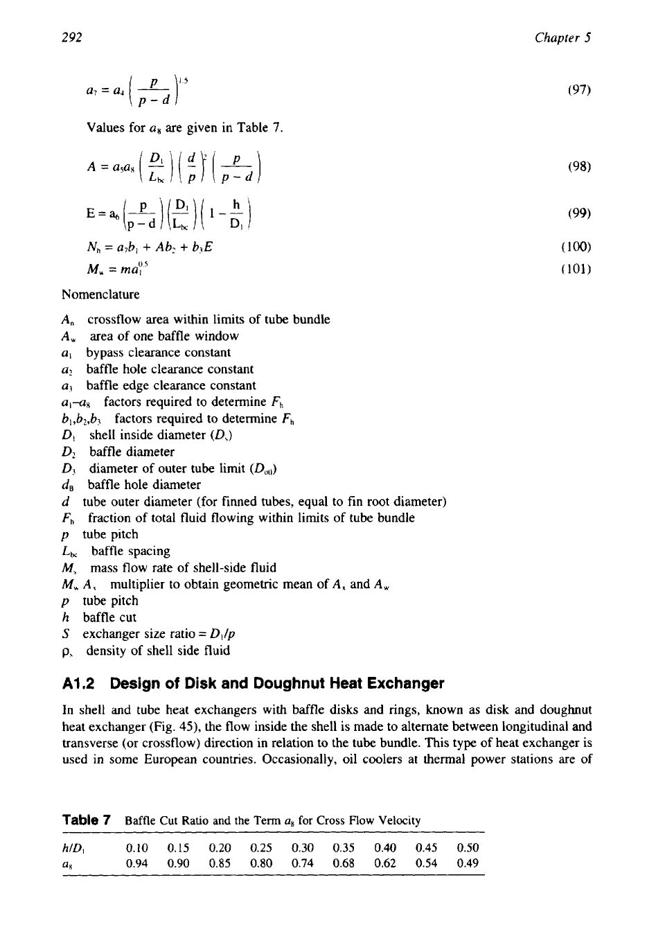
Values for
an
are given in Table
7.
Nh
=
a7bl
+
Abz
+
b3E
M,
=
may.5
Nomenclature
crossflow area within limits of tube bundle
area of one baffle window
bypass clearance constant
baffle hole clearance constant
baffle edge clearance constant
al-a8
factors required to determine
Fh
b,,b2,b3
factors required to determine
Fh
shell inside diameter
(D,)
baffle diameter
diameter of outer tube limit
(Do,,)
baffle hole diameter
tube outer diameter (for finned tubes, equal
to
fin root diameter)
fraction
of
total fluid flowing within limits of tube bundle
tube pitch
baffle spacing
mass flow rate of shell-side fluid
M,
A,
multiplier to obtain geometric mean of
A,
and
A,
p
tube pitch
h
baffle cut
S
exchanger size ratio
=
D,/p
p.,
density of shell side fluid
A1.2
Design
of
Disk and Doughnut Heat Exchanger
In shell and tube heat exchangers with baffle disks and rings, known as disk and doughnut
heat exchanger (Fig.
43,
the flow inside the shell is made to alternate between longitudinal and
transverse (or crossflow) direction in relation to the tube bundle. This type of heat exchanger is
used in some European countries. Occasionally, oil coolers at thermal power stations are of
Table
7
Baffle
Cut
Ratio
and
the
Term
u8
for
Cross
Flow
Velocity
hlD,
0.10
0.15
0.20
0.25
0.30
0.35
0.40
0.45
0.50
QX
0.94 0.90
0.85
0.80
0.74
0.68
0.62
0.54
0.49
293
Shell and Tube Heat Exchanger Design
this type. It has been reported that for the same pressure drop in shell-side fluid, the heat-
transfer coefficient obtained with disk and doughnut baffles is approximately 15% more than
that obtained with segmental baffles
[52].
Exchangers are fabricated for horizontal or vertical
installation.
Design Method
The effect of clearance between segmental baffles and the shell on the performance of a heat
exchanger has been reasonably well studied, but there is hardly any corresponding published
literature available for the disk and doughnut type heat exchangers. Very few open literature
methods are available for the thermal design of disk and doughnut heat exchangers. Notable
among them are Donohue
[53],
Slipcevic
[54,55],
and Goyal et al.
[56].
Donohue's thermal
design method was recently discussed by Ratnasamy
[57].
In this section, the Slipcevic and
Donohue's method are discussed.
Slipcevic Method
Design Considerations.
Follow these design guidelines
on
the shell side
[54]:
The spacing between the baffle disks and rings usually amounts to
2045%
of the inside
shell diameter. Less than
15%
is not advisable.
Since the heat-transfer coefficient for flow parallel with the tubes is lower than that for
flow normal to the tubes, space the baffle plates
so
that the velocity in the baffle spacing
opening is higher than that
of
the flow normal to the tubes.
It is advisable to make the annular area between the disk and the shell,
&,
the same as
the area inside the ring,
&,
such that
Heat Transfer.
Step 1. Calculate the individual flow area for longitudinal flow:
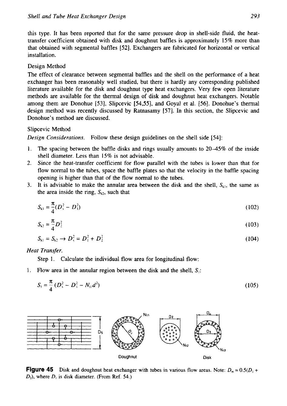
1. Flow area in the annular region between the disk and the shell,
SI:
7
0s
mN12
1
Doughnut
Disk
Figure
45
Disk
and doughnut heat exchanger with tubes in
various
flow
areas.
Note:
D,
=
0.5(D1
+
D2),
where
D,
is
disk diameter. (From Ref.
54.)