Kuppan T. Heat Exchanger Design Handbook
Подождите немного. Документ загружается.

254
Chapter
5
the floating tube sheet moves back and forth. The lantern ring is packed on both sides, and
is
provided with vent or weep holes
so
that leakage through either should be to the outside.
Number of tube passes is limited to one or two. The tube bundle is removable.
Floating Head, Pull Through Floating Head
In the floating head (T head), pull through head exchanger, a separate head or cover is bolted
to the floating tube sheet within the shell. In this design, the tube bundle can be removed
without dismantling the joints at the floating end. Due to the floating head bonnet flange and
bolt circle, many tubes are omitted from the tube bundle at the tube bundle periphery and
hence it accommodates the smallest number of tubes for a given shell diameter. This results
in the largest bundle-to-shell clearance or a significant bundle-to-shell bypass stream
C.
To
overcome the reduction in thermal performance, sealing devices are normally required and
the
shell diameter is somewhat increased to accommodate a required amount of surface area.
An
ideal application for the T head design is as the kettle reboiler, in which there
is
ample space
on the shell side and the flow bypass stream
C
is of no concern.
Floating Head with Backing Device
In the floating head
(S
head) with backing device, the floating head cover (instead of being
bolted directly to the floating tube sheet as in the pull through type) is bolted to a split backing
ring. The shell cover over the floating head has
a
diameter larger than the shell.
As
a result,
the bundle to shell clearance is reasonable and sealing strips are generally
not
required. The
tube bundle is not removable. Both ends of the heat exchanger must be disassembled for
cleaning and maintenance.
11.4
Differential Thermal Expansion
Means should be identified to accommodate the thermal expansion or contraction between the
shell and the tube bundle due to high mean metal temperature differentials between the shell
and the tube bundle. This is particularly true for fixed tube-sheet exchangers. Differential
thermal expansion is overcome by the following means in the shell and tube heat exchangers:
U-Tube Design.
The U-bend design allows each tube to expand and contract independently.
Fixed Tube-Sheet Design.
For fixed tube-sheet exchangers, when the difference between shell
and tube mean metal temperatures becomes large (greater than approximately
50°C
for carbon
steel), the tube-sheet thickness and tube end loads become excessive [29]. When a thermal
expansion problems exists, an expansion joint is incorporated in the shell. This permits the
shell to expand and contract.
Flouting Head Designs.
The floating head exchangers solve the expansion problem by having
one stationary tube sheet, and one floating tube sheet that
is
free to accommodate the thermal
expansion of the tube bundle.
12
TEMA CLASSIFICATION OF HEAT EXCHANGERS
TEMA has set up mechanical standards for three classes of shell and tube heat exchangers:
R,
C,
and
B
[3].
Class
R
heat exchangers specify design and fabrication of unfired shell and tube
heat exchangers for the generally severe requirements of petroleum and related processing
applications, class
C
for the generally moderate requirements of commercial and general
pro-
cess applications, and class B for chemical process service. Salient features of TEMA standards
are discussed in Chapter 11. Table
2
shows some major differences between TEMA classes
R,
C.
and B.
255
Shell
and
Tube Heat Exchanger Design
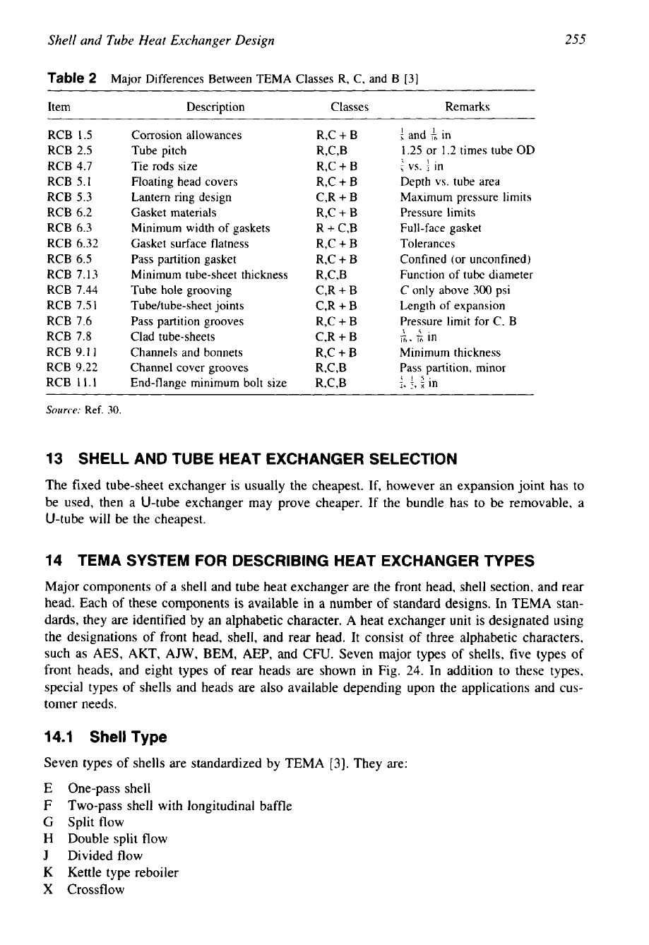
Table
2
Major Differences Between TEMA Classes R, C, and B [3]
Item Description Classes Re marks
RCB 1.5
Corrosion allowances
R,C
+
B
and in
RCB
2.5
Tube pitch
R,C,B
1.25
or 1.2 times tube
OD
RCB 4.7
Tie rods size
R,C
+
B
t
vs.
{
in
RCB 5.1
Floating head covers
R,C
+
B
Depth vs. tube area
RCB
5.3
Lantern ring design
C,R
+
B
Maximum pressure limits
RCB 6.2
Gasket materials
R,C
+
B
Pressure limits
RCB 6.3
RCB 6.32
Minimum width of gaskets
Gasket surface flatness
R
+
C,B
R,C
+
B
Full-face gasket
Tolerances
RCB 6.5
Pass partition gasket
R,C
+
B
Confined (or unconfined)
RCB 7.13
Minimum tube-sheet thickness
R,C,B
Function of tube diameter
RCB 7.44
Tube hole grooving
C,R
+
B
C
only above
300
psi
RCB 7.51
Tubehube-sheet
joints
C,R
+
B
Length
of
expansion
RCB 7.6
RCB 7.8
Pass partition grooves
Clad tube-sheets
R,C
+
B
C,R
+
B
Pressure limit for C, B
I63
El
In
1
5.
-
RCB 9.11
Channels and bonnets
R,C
+
B
Minimum thickness
RCB 9.22
Channel cover grooves
W,B
Pass partition, minor
RCB 11.1
End-flange minimum bolt size
W,B
IL!
5,
:,
in
Source:
Ref.
30.
13
SHELL AND TUBE HEAT EXCHANGER SELECTION
The fixed tube-sheet exchanger is usually the cheapest. If, however an expansion joint has to
be used, then a U-tube exchanger may prove cheaper. If the bundle has to
be
removable, a
U-tube will be the cheapest.
14
TEMA SYSTEM
FOR
DESCRIBING HEAT EXCHANGER
TYPES
Major components
of
a
shell and tube heat exchanger are the front head, shell section, and rear
head. Each of these components is available in a number of standard designs.
In
TEMA stan-
dards, they are identified by an alphabetic character. A heat exchanger unit is designated using
the designations of front head, shell, and rear head. It consist of three alphabetic characters,
such as AES, AKT, AJW,
BEM,
AEP, and
CFU.
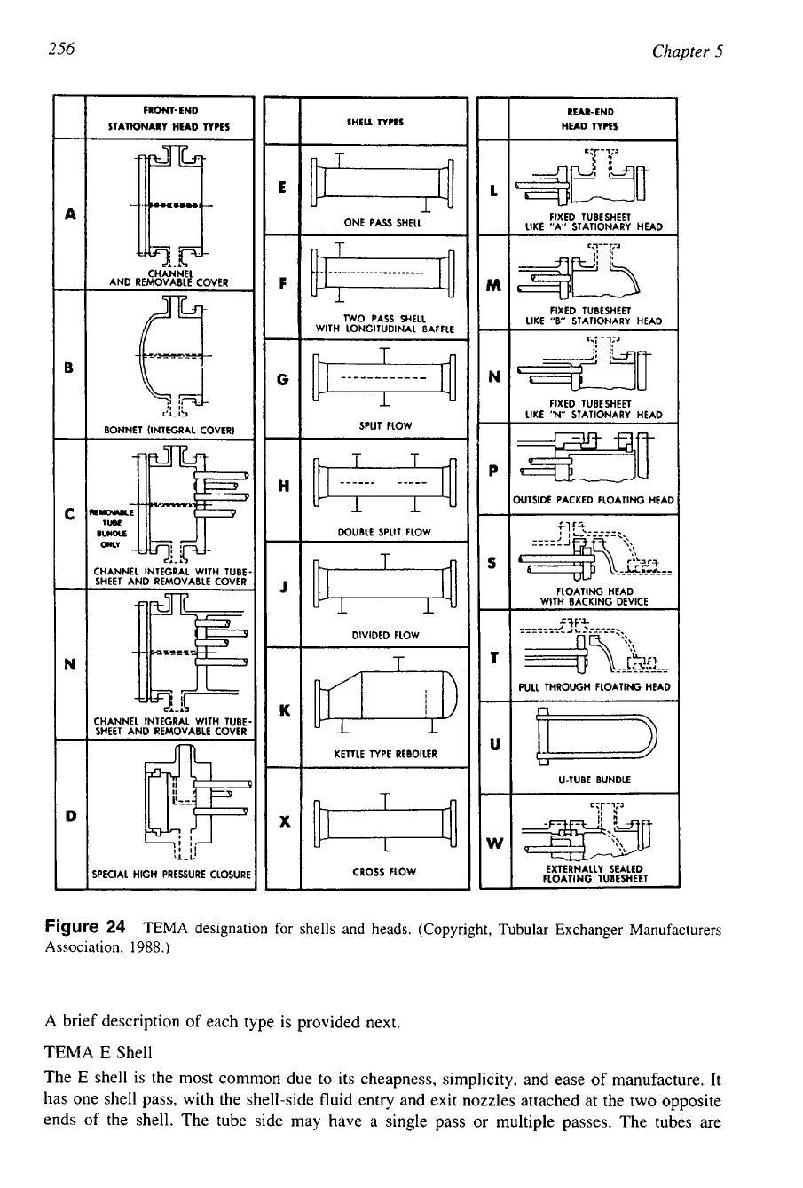
Seven major types of shells, five types
of
front heads, and eight types of rear heads are shown in Fig. 24. In addition to these types,
special types of shells and heads are also available depending upon the applications and cus-
tomer needs.
14.1
Shell
Type
Seven types of shells are standardized by TEMA
[3].
They are:
One-pass shell
Two-pass shell with longitudinal baffle
Split flow
Double split flow
Divided flow
Kettle type reboiler
Cross flow
Chapter
5
FRONT-END RUR-END
STATIONARY HEAD
TYPES
SHEU
TYPES
HEAD
TYPES
FIXED TUBESHEET
ONE PASS SHELL
LIKE "A" STATIONARY
HEAD
CHANNEL
AND REMOVABLE COVER
FIXED TUBESHEET
WO
PASS SHELL
LIKE
"B'
STATIONARY HEAD
WITH LONGITUDINAL BAFFLE
,~
-~~
I'
FIXED TUBESHEFT
1,i-i5
LIKE
"N"
STATIONARY HEAD
BONNET (INTEGRAL COVER)
XJTSIDE PACKED FLOATING
HEN
DOUBLE SPLIT FLOW
T
CHANNEL INTEGRAL WITH TUBE
SHEET AND REMOVABLE COVER
FLOATING HEAD
WITH BACKING DEVICE
DIVIDED FLOW
T
L
JL
CHANNEL INTEGRAL WITH TUBE
SHEET AND REMOVABLE COVER
KETTLE TYPE REBOILER
-
U-TUBE BUNDLE
I
EXTERNALLY SEALED
SPKIAL
HIGH
PRESSURE CLOSURI
CROSS FLOW
FLOATING TUBESHEET
Figure
24
TEMA designation for shells and heads. (Copyright, Tubular Exchanger Manufacturers
Association,
1988.)
A
brief description of each type is provided next.
TEMA
E
Shell
The
E
shell is the most common due to its cheapness, simplicity, and ease
of
manufacture. It
has one shell pass, with the shell-side fluid entry and exit nozzles attached at the two opposite
ends of the shell. The tube side may have a single pass
or
multiple passes. The tubes are
----
257
Shell and
Tube
Heat Exchanger Design
supported by transverse baffles. This shell is the most common for single-phase shell fluid
applications. Multiple passes on the tube side reduce the exchanger effectiveness or
LMTD
correction factor
F
over a single pass arrangement. If F is too low, two
E
shells in series may
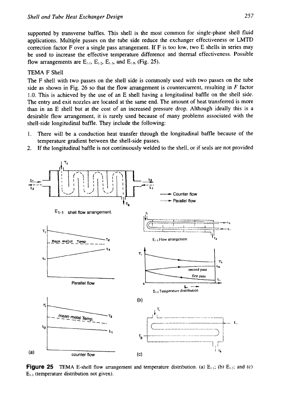
be used to increase the effective temperature difference and thermal effectiveness. Possible
(Fig.
25).
flow arrangements are
El-),
El-*,
and
EISN
TEMA
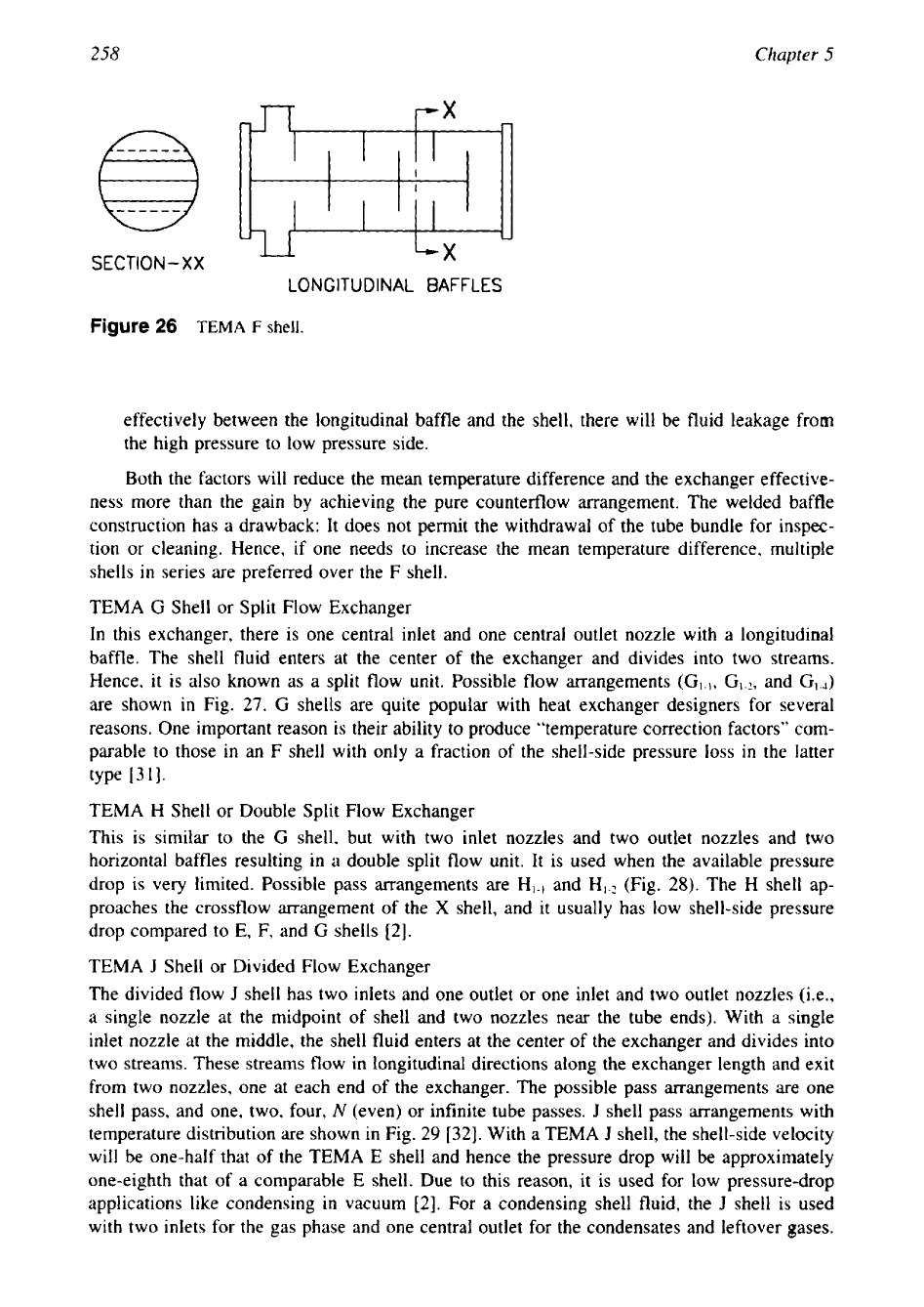
F
Shell
The
F
shell with two passes on the shell side is commonly used with two passes on the tube
side as shown in Fig.
26
so
that the flow arrangement
is
countercurrent, resulting in
F
factor
1.0.
This is achieved by the use of
an
E
shell having a longitudinal baffle on the shell side.
The entry and exit nozzles are located at the same end. The amount of heat transferred is more
than in an
E
shell but at the cost of an increased pressure drop. Although ideally this is a
desirable flow arrangement, it is rarely used because of many problems associated with the
shell-side longitudinal baffle. They include the following:
1.
There will be a conduction heat transfer through the longitudinal baffle because of the
temperature gradient between the shell-side passes.
2.
If the longitudinal baffle is not continuously welded to the shell,
or
if seals are not provided
tl
t2
-
Counter
flow
t
To
-----+
Parallel
flow
-1
shell
flow
arrangement.
Flow
arrangement
to
second
pass
first
pass
tl
._-__
Parallel
flow
T'QQ
E,
Temperature distnbution
k-
Figure
25
TEMA
E-shell
flow
arrangement and temperature distribution. (a)
El.,;
(b)
E,.?;
and
(c)
(temperature distribution not given).
258
Chapter
5
SECTION-XX
LONGITUDINAL BAFFLES
Figure
26
TEMA
F
shell.
effectively between the longitudinal baffle and the shell, there will
be
fluid leakage from
the high pressure to low pressure side.
Both the factors will reduce the mean temperature difference and the exchanger effective-
ness more than the gain by achieving the pure counterflow arrangement. The welded baffle
construction has a drawback: It does not permit the withdrawal of the tube bundle for inspec-
tion or cleaning. Hence, if one needs to increase the mean temperature difference, multiple
shells
in
series are preferred over the F shell.
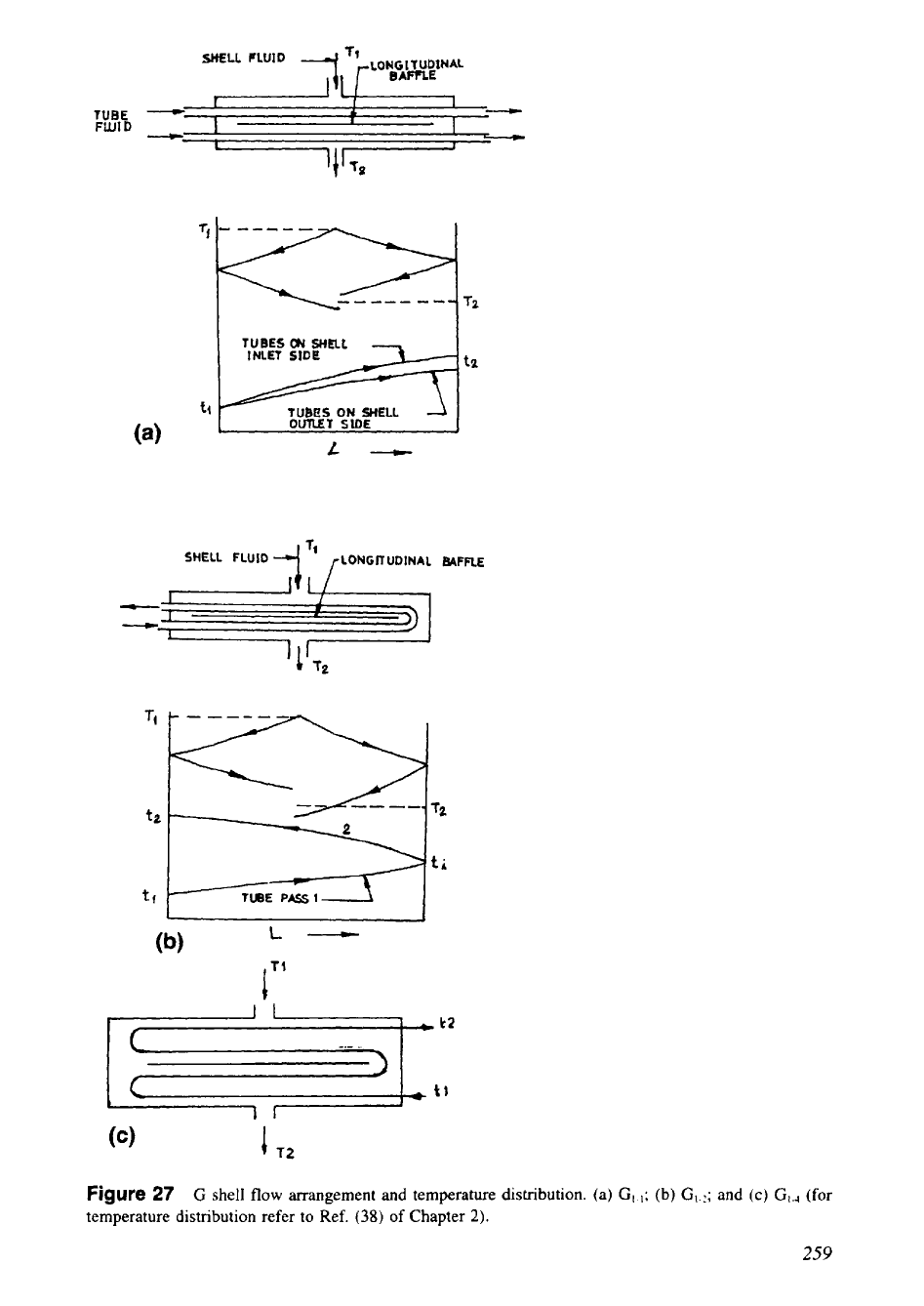
TEMA
G
Shell or Split Flow Exchanger
In this exchanger, there is one central inlet and one central outlet nozzle with a longitudinal
baffle. The shell fluid enters at the center of the exchanger and divides into two streams.
Hence,
it
is also known as a split flow unit. Possible flow arrangements
(GI.I,
Gl.?,
and
G,.J
are shown in Fig.
27.
G
shells are quite popular with heat exchanger designers for several
reasons. One important reason is their ability to produce “temperature correction factors” com-
parable to those
in
an F shell with only a fraction of the shell-side pressure
loss
in
the latter
type
13
11.
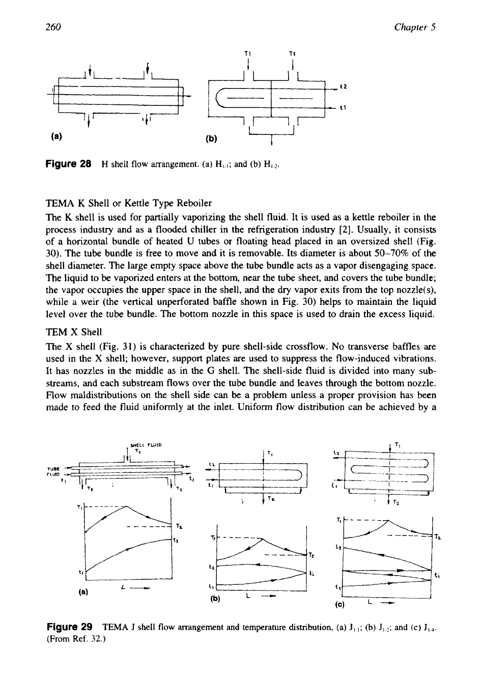
TEMA H Shell or Double Split Flow Exchanger
This is similar to the
G
shell, but with two inlet nozzles and two outlet nozzles and two
horizontal baffles resulting in a double split flow unit. It is used when the available pressure
drop is very limited. Possible pass arrangements are and
HI-?
(Fig.
28).
The H shell ap-
proaches the crossflow arrangement of the
X
shell, and it usually has low shell-side pressure
drop compared to E,
F,
and
G
shells
[2].
TEMA
J
Shell or Divided Flow Exchanger
The divided flow
J
shell has two inlets and one outlet or one inlet and two outlet nozzles (i.e.,
a single nozzle at the midpoint of shell and two nozzles near the tube ends). With a single
inlet nozzle at the middle, the shell fluid enters at the center of the exchanger and divides into
two streams. These streams flow in longitudinal directions along the exchanger length and exit
from two nozzles, one at each end of the exchanger. The possible pass arrangements are one
shell pass, and one, two, four,
N
(even) or infinite tube passes.
J
shell pass arrangements with
temperature distribution are shown in Fig.
29
[32].
With a TEMA
J
shell, the shell-side velocity
will be one-half that
of
the TEMA
E
shell and hence the pressure drop will be approximately
one-eighth that of a comparable
E
shell. Due to this reason, it is used for low pressure-drop
applications like condensing
in
vacuum
[2].
For a condensing shell fluid, the
J
shell is used
with two inlets for the gas phase and one central outlet for the condensates and leftover gases.
I
,
,
SHELL
FLUID
'9
,-LONGITUDINAL
BAFlrLE
TUBES
ON SHELL
INLET
SIDE
tU8ES
ON
SHELL
L-m-
SHELL
FLUID
LONGK
UDlNAL
MFFLE
I
f2
tf
L-
IT'
Figure
27
G
shell
flow
arrangement
and
temperature distribution. (a) G,.,;(b)
G,..;
and
(c)
G,,
(for
temperature distribution refer to Ref.
(38)
of Chapter
2).
259
260
Chapter
5
t2
tl
Figure
28
H
shell flow arrangement.
(a)
and
(b)
TEMA
K
Shell or Kettle Type Reboiler
The
K
shell is used for partially vaporizing the shell fluid. It is used as a kettle reboiler in the
process industry and as a flooded chiller in the refrigeration industry
[2].
Usually, it consists
of a horizontal bundle
of
heated U tubes
or
floating head placed in an oversized shell
(Fig.
30).
The tube bundle is free to move and it is removable. Its diameter is about
50-70%
of the
shell diameter. The large empty space above the tube bundle acts as a vapor disengaging space.
The liquid to be vaporized enters at the bottom, near the tube sheet, and covers the tube bundle;
the vapor occupies the upper space in the shell, and the
dry
vapor exits from the top nozzle(s),
while a weir (the vertical unperforated baffle shown in Fig.
30)
helps to maintain the liquid
level over the tube bundle. The bottom nozzle in this space is used
to
drain the excess liquid.
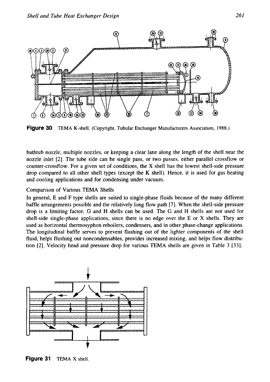
TEM
X
Shell
The
X
shell (Fig.
31)
is characterized by pure shell-side crossflow.
No
transverse baffles are
used in the
X
shell; however, support plates are used to suppress the flow-induced vibrations.
It has nozzles in the middle as in the
G
shell. The shell-side fluid is divided into many sub-
streams, and each substream flows over the tube bundle and leaves through the bottom nozzle.
Flow maldistributions on the shell side can be a problem unless a proper provision has been
made to feed the fluid uniformly at the inlet. Uniform flow distribution can be achieved by a
Figure
29
TEMA
J
shell
flow
arrangement and temperature distribution,
(a)
JI.,;
(b)
J1.:;
and
(c)
JI.+
(From Ref.
32.)
261
Shell
and
Tube
Heat
Exchanger
Design
Figure
30
TEMA
K-shell.
(Copyright,
Tubular
Exchanger Manufacturers Association,
1988.)
bathtub nozzle, multiple nozzles, or keeping a clear lane along the length of the shell near the
nozzle inlet
[2].
The tube side can be single pass, or two passes, either parallel crossflow or
counter-crossflow. For a given set of conditions, the
X
shell has the lowest shell-side pressure
drop compared to all other shell types (except the
K
shell). Hence, it is used for gas heating
and cooling applications and for condensing under vacuum.
Comparison of Various
TEMA
Shells
In general,
E
and
F
type shells are suited to single-phase fluids because of the many different
baffle arrangements possible and the relatively long flow path
[7].
When the shell-side pressure
drop is a limiting factor,
G
and H shells can be used. The
G
and H shells are not used for
shell-side single-phase applications, since there is no edge over the
E
or
X
shells. They are
used as horizontal thermosyphon reboilers, condensers, and in other phase-change applications.
The longitudinal baffle serves to prevent flashing out of the lighter components of the shell
fluid, helps flushing out noncondensables, provides increased mixing, and helps flow distribu-
tion
[2].
Velocity head and pressure drop for various TEMA shells are given in Table
3 [33].
c
Figure
31
TEMA
X
shell.

262
Chapter
5
Table
3
Shellside Velocity Head
and
Pressure Drop
for
Some
TEMA
Shells
[33]
~~
~~ ~ ~ ~ ~~~
TEMA shell type Velocity head Pressure drop
E
shell
V
aV
?L
F
shell
2v
a8V'L
G
shell
V
aV
'L
H shell
vi2
aV'W8
J
shell
vi2
aV'W8
Source:
Ref.
33.
14.2
Front and Rear Head Designs
Head designs can
vary
from plain standard castings to fabricated assemblies with many special
features. Two
of
the major considerations in the choice of heads are
[4]
(1)
accessibility to the
tubes, and
(2)
piping convenience. Where fouling conditions are encountered or where frequent
access for inspection is desired, a head or cover plate that can be easily removed is an obvious
choice. In this head, connections are located
on
the sides, not on the ends of removable heads.
Typical open end heads used for this purpose are called channels. They are fabricated from
cylindrical shells and fitted with easily removable cover plates
so
that the tubes can be cleaned
without disturbing piping.
Designations for Head Types
Front Head.
For the variable front head, the constants and their meanings are:
A
Channel with removable cover
B Bonnet with integral cover
C
Channel integral with the tube sheet and removable cover when the tube bundle is remov-
able
N
Channel integral with the tube sheet and having a removable cover but the tube bundle is
not removable
D Special high-pressure closure
Rear
Head.
L
Fixed tube sheet like
A
stationary head
M
Fixed tube sheet like
B
stationary head
N
Fixed tube sheet like
N
stationary head
P
Outside packed floating head
S
Floating head with backing device
T
Pull through floating head
U
U-tube bundle
W
Externally sealed floating tube sheet
Salient features of these heads are discussed and tabulated by Larowski et al.
[7].
15
SHELLSIDE CLEARANCES
Even though one of the major functions of the plate baffle is to induce crossflow over the tube
bundle, this objective is achieved partially. Various clearances on the shell side partially bypass
the fluid. Bypassing
is
defined as a leakage flow where fluid from the crossflow stream, in-
Shell
and Tube Heat Exchanger Design
263
tended to flow through the tube bundle, avoids flowing through it by passing through an
alternative, low-resistance flow path [34]. A major source of bypassing is the shell-side clear-
ances. Clearances are required for heat exchanger fabrication. Fabrication clearances and toler-
ances have been established by the Tubular Exchanger Manufacturers Association (TEMA)
[3], and these have become widely accepted around the world and are enforced through inspec-
tion during fabrication. Three clearances are normally associated with a plate baffle exchanger.
They are (1) tube to baffle hole, (2) baffle to shell, and (3) bundle to shell. Additionally, in a
multipass unit, the tube layout partitions may create open passages for the bypass of the cross-
flow stream. Since bypassing reduces heat transfer on the shell side, to achieve good shell-side
heat transfer, bypassing of the fluid must be reduced. These clearances and their effect on the
shell-side performance are discussed in detail next.
15.1
Tube-to-Baff le-Hole Clearance
The holes in the baffles must be slightly larger than the tube outer diameter to ensure easy
tube insertion. The resultant clearance is referred to as the tube-to-baffle-hole clearance. It
should be kept at
a
minimum
(1)
to reduce the flow-induced vibration and (2) to minimize the
A leakage stream (various shellside bypass streams are discussed next). As per TEMA
RCB-
4.2, where the maximum unsupported tube length is 36 in (914.4 mm) or less, or for tubes
larger than 1.25 in (31.8 mm) outer diameter, the clearance is
&
in
(0.80
mm); where the
unsupported tube length exceeds
36
in for tube outer diameter 1.25 in or smaller, the clearance
is
$
in (0.40 mm).
15.2 Shell-to-Baff le Clearance
The clearance between the shell inner diameter and baffle outer diameter is referred to as the
baffle-to-shell clearance. It should be kept to a minimum to minimize the
E
leakage stream.
TEMA recommend maximum clearance as per RCB-4.3 [3] varies from 0.125 in (3.175 mm)
for 6 in (152.4 mm) shell inner diameter to 0.315 in (7.94 mm) for
60
in (1524 mm) shell
inner diameter.
15.3
Shell-to-Bundle Clearance
Since the tube bundle does not fill the shell, there
is
a shell-to-bundle clearance. This allows
the so-called bypass
stream
C
flowing around the bundle. Sealing strips are used to block this
space and force the bypass stream to flow across the tubes. The use of sealing strips is recom-
mended every five to seven rows of tubes in the bypass stream direction.
15.4
Bypass Lanes
The lanes provided for the tubeside partition ribs is a source of bypass on the shell side. The
pass partition lanes (Fig. 32) are, however, placed perpendicular to the crossflow whenever
possible, or the bypass lanes are usually blocked by tie rods, which act similar to the sealing
strips. Hence, the effect of the bypass lanes on thermal performance is usually can be neglected.
16 DESIGN METHODOLOGY
16.1 Shell-Side
Flow
Pattern
Shell Fluid Bypassing and Leakage
In shell and tube exchangers with segmental plate baffles, the shell-side flow is very complex
due to a substantial portion of the fluid bypassing the tube bundle through various shell-side