Kuppan T. Heat Exchanger Design Handbook
Подождите немного. Документ загружается.


234
Chapter
S
access to the tubes for cleaning as required by process conditions. Four standard types of tube
layout patterns are triangular (30"), rotated triangular (60"), square
(90"),
and rotated square
(45").
(Note that the tube layout angle is defined in relation to the flow direction and is not
related to the horizontal or vertical reference line arrangement, and that the 30°,
60°,
and
45'
arrangements are "staggered," and
90"
is "in-line.") For identical tube pitch and flow rates, the
tube layouts in decreasing order of shell-side heat-transfer coefficient and pressure drop
are
30°,
45",
60°, and
90".
Thus the
90"
layout will have the lowest heat-transfer coefficient and
pressure drop. The selection of the tube layout pattern depends on the following parameters,
which influence the shell-side performance and hence the overall performance:
1.
Compactness
2.
Heat transfer
3. Pressure drop
4.
Accessibility for mechanical cleaning
5.
Phase change
if
any on the shell side
Triangular and Rotated Triangular Arrangements
Triangular and rotated triangular layouts
(30"
and 60") provide a compact arrangement, better
shell-side heat-transfer coefficients, and stronger tube sheets for a specified shell-side flow
area. For a given tube pitchloutside diameter ratio, about 15% more tubes can be accommo-
dated within a given shell diameter using these layouts
[6].
These layout patterns are satisfac-
tory for clean services, but have the disadvantage of making the lanes between tubes rather
inaccessible for mechanical cleaning. It is difficult to insert a rigid tool between the tubes.
Only chemical cleaning or water jet cleaning is possible.
Square and Rotated Square Arrangements
When mechanical cleaning is necessary on the shell side,
45"
and
90"
layouts must be used
with a minimum gap between tubes
of
6.35 mm. There is no theoretical limit to tube outer
diameter for mechanical cleaning, but the 6.35 mm clearance limits the tubes to a minimum
of
2
or
in
outer diameter
in
practice
[7].
The square pitch is generally not used in the fixed
tube-sheet design because of no need of mechanical cleaning on the shell side. These layout
patterns offer lower pressure drops and lower heat-transfer coefficients than triangular pitch.
The
45"
layout is preferred for single-phase laminar flow or fouling service, and for condensing
fluid on the shell side. Shah
121
suggests a square layout for the following applications:
1.
If the pressure drop is a constraint on the shell side, the
90"
layout is used for turbulent
flow, since in turbulent flow the
90"
has superior heat-transfer rate and
less
pressure drop.
2.
For reboilers, a square layout will be preferred for stability reasons. The
90"
layout pro-
vides vapor escape lanes.
4
BAFFLES
Baffles must generally be employed on the shell-side to support the tubes, to maintain the tube
spacing, and to direct the shell-side fluid across or along the tube bundle in a specified manner.
There are a number of different types of baffles and these may be installed in different ways
to
provide the flow pattern required for a given application.
4.1 Classification of Baffles
Baffles are either normal or parallel to the tubes. Accordingly, baffles may be classified as
transverse or longitudinal. The transverse baffles direct the shell-side fluid into the tube bundle

Shell and Tube Heat Exchanger Design
235
at approximately right angles to the tubes, and increase the turbulence of the shell fluid. Every
shell and tube exchanger has transverse baffles except the
X
and
K
shells, which have only
support plates. The longitudinal baffles are used to control the direction of the shell side flow.
For example, F,
G,
and
H
shells have longitudinal baffles. In the
F
shell,
an
overall counterflow
is achieved.
4.2
Transverse Baffles
Transverse baffles are of two types:
(1)
plate baffles and
(2)
rod baffles. Three types of plate
baffles are
(1)
segmental, (2) disk and doughnut, and
(3)
orifice baffles.
Segmental Baffles
The segmental baffle is a circular disk (with baffle holes) having a segment removed. Predomi-
nantly, a large number of shell and tube exchangers employ segmental baffles. This cutting is
denoted as the baffle cut and it is commonly expressed as a percentage of the shell inside
diameter as shown in Fig.
5.
Here the percent baffle cut is the height,
H,
given as a percentage
of the shell inside diameter,
D,.
The segmental baffle is also referred to as a single segmental
baffle. The heat transfer and pressure drop of crossflow bundles are greatly affected by the
baffle cut. The baffle cuts vary from
20
to 49% with the most common being
20-25%,
and
the optimum baffle cut is generally
20%,
as it affords the highest heat transfer for a given
pressure drop. Baffle cuts smaller than
20%
can result in high pressure drop.
As
the baffle cut
increases beyond 20%, the flow pattern deviates more and more from crossflow
[5]
and can
result in stagnant regions or areas with lower flow velocities; both of these reduce the thermal
effectiveness of the bundle
[
11.
Bane Spacing.
The practical range of single-segmental baffle spacing is to
1
shell diameter
[l],
though optimum could be 40-50%
[2].
TEMA
Table RCB-4.52
[3]
provides maximum
baffle spacing for various tube outer diameters, tube materials, and the corresponding maxi-
mum allowable temperature limit. The baffles are generally spaced between the nozzles. The
inlet and outlet baffle spacings are in general larger than the “central” baffle spacing to accom-
modate the nozzles, since the nozzle dimensions frequently require that the nozzle should be
located far enough from the tube sheets.
Figure
5
Baffle cut.

236
Chapter
5
Figure
6
Shellside
flow
distribution influenced by baffle cut,
Ref.
(13).
Bafle Thickness.
TEMA Tables
R-4.41
and
CB-4.41 [3]
provide the minimum thickness of
transverse baffles applying to all materials for various shell diameters and plate spacings.
Shell-Side Flow Distribution.
Segmental baffles have a tendency to poor flow distribution if
spacing or baffle cut ratio is not in correct proportion, as shown in Fig.
6
[13].
Too
low or
too high a ratio results in maldistribution and produces inefficient heat transfer and also favors
fouling. For low-pressure-drop designs, choose baffles that ensure a more uniform flow such
as multisegmental, disc and doughnuts, and rod baffles.
Orientation
of
Bafles.
Alternate segmental baffles are arranged at 180" to each other, which
cause shell-side flow to approach crossflow through the bundle and axial flow in the baffle
window zone. All segmental baffles shown in Fig. 7a have horizontal baffle cuts. Unless the
shell-side fluid is condensed, the horizontal baffle cut should be used for single-phase applica-
tion,
to
reduce accumulation of deposits on the bottom
of
the shell and to prevent stratification
of the shell-side fluid
[5].
The direction of the baffle cut is selected as vertical (Fig. 7b) for
the following shell-side applications
[6]:
(1)
for condensation,
to
allow the condensate
to
flow
freely to the outlet without covering an excessive amount of tubes
[2,5];
(2)
for boiling or
condensing fluids, to promote more uniform flow; and
(3)
for solids entrained in liquid (to
provide least interference for the solids to fall out).
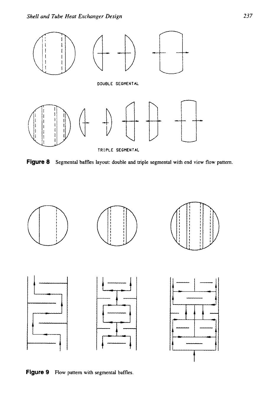
Double Segmental and Multiple Segmental
Baffles
Various multisegmental baffles can be used to reduce baffle spacing, or to reduce crossflow
because of pressure limitations. The multisegmental baffles are characterized by large open
areas and some allow the fluid to flow nearly parallel to the tubes, offering a much lower
pressure drop
[
141.
Segmental baffle layout is shown in Fig.
8
and flow distribution in Fig. 9. In an exchanger
with single segmental baffles the total flow, except for leakages and bypass streams, passes
through the tube bank between baffles in crossflow as shown in Fig. 9a, whereas with double
Figure
7
Baffle cut orientation: (a) horizontal; (b) vertical; and (c) rotated.
237
Shell and Tube Heat Exchanger Design
DOUBLE
SEGMENTAL
TRIPLE
SEGMENTAL
Figure
8
Segmental baffles layout: double
and
triple segmental with end view flow pattern.
Figure
9
Flow pattern with segmental baffles.
238
Chapter
5
segmental baffles barring the leakages, the flow divides into two streams on either side of the
shell (Fig. 9b), and in triple segmental baffles, the flow divides into three streams (Fig. 9c).
Due to this, heat exchangers with double or multiple segmental baffles can handle larger fluid
flows on the shell side. Other features of double segmental or multiple segmental baffles are
as follows [2]:
1.
The flow on the shell side is split into two or more streams as per the number of baffle
segments, namely, double, triple, multiple, etc.; hence, the danger of shell-side flow-in-
duced vibration
is
minimal.
2.
The baffle spacing should not be too small; otherwise it results in a more parallel (longitu-
dinal) flow with significant low stagnant areas.
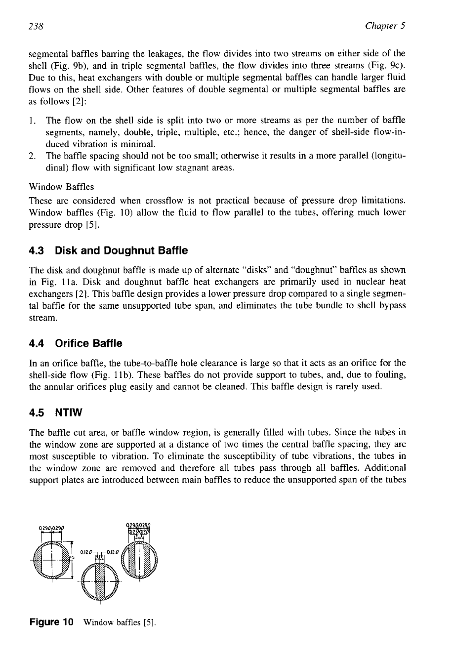
Window Baffles
These are considered when crossflow is not practical because of pressure drop limitations.
Window baffles (Fig. 10) allow the fluid to flow parallel to the tubes, offering much lower
pressure drop
[5].
4.3
Disk
and Doughnut Baffle
The disk and doughnut baffle is made up of alternate “disks” and “doughnut” baffles as shown
in Fig. lla. Disk and doughnut baffle heat exchangers are primarily used in nuclear heat
exchangers [2]. This baffle design provides a lower pressure drop compared to a single segmen-
tal baffle for the same unsupported tube span, and eliminates the tube bundle to shell bypass
stream.
4.4
Orifice Baffle
In an orifice baffle, the tube-to-baffle hole clearance is large
so
that it acts as an orifice for the
shell-side flow (Fig. llb). These baffles do not provide support to tubes, and, due to fouling,
the annular orifices plug easily and cannot be cleaned. This baffle design is rarely used.
4.5
NTlW
The baffle cut area, or baffle window region, is generally filled with tubes. Since the tubes in
the window zone are supported at a distance of two times the central baffle spacing, they are
most susceptible to vibration. To eliminate the susceptibility of tube vibrations, the tubes in
the window zone are removed and therefore all tubes pass through all baffles. Additional
support plates are introduced between main baffles to reduce the unsupported span of the tubes
Figure
10
Window
baffles
[5].

239
Shell and Tube Heat Exchanger Design
orifice
baffles
,
f
Disk
4
Doughnut
2
Disk
Figure
11
Nonsegmental
circular
baffles. (a)
Orifice
baffle, and (b) disk and doughnut
baffles.
as shown in Fig.
12,
thus providing an increase in the natural frequency of the tubes. The
resultant design is referred to as the segmental baffle with no-tubes-in-window
(NTIW)
design.
NTIW
design has the following characteristics
[
151:
1.
Pressure drop about one-third that
of
single segmental baffle design.
2.
Uniform shell-side flow pattern resembling that of an ideal tube bank, which offers high
shell-side heat-transfer coefficient and low fouling tendency.
Figure
12
No
tube in window design
(NTIW).
240
Chapter
5
3.
The baffle cut and number of tubes removed varies from 15 to
25%.
4.
Very low pressure drop
in
the window and correspondingly lower bypass and leakage
streams.
Since the loss
in
heat transfer surface is considerable in an
NTIW
design, this can ba
minimized by having small baffle cuts and possibly by
an
increase
in
the shell-side fluid
velocity or larger shell diameter to contain the same number of tubes.
4.6
Longitudinal
Baffles
Longitudinal baffles divide the shell into two or more sections, providing multipass on the
shellside. But this type should not be used unless the baffle is welded to the shell and
tube
sheet. Nevertheless, several sealing devices have been tried to seal the baffle and the shell, but
none has been very effective [5]. Gupta [16] lists some sealing devices that
are
used to seal
the baffle
and
shell. They are:
Sealing strips or multiflex arrangement
Packing arrangement
Slide-in or tongue-and-groove arrangement
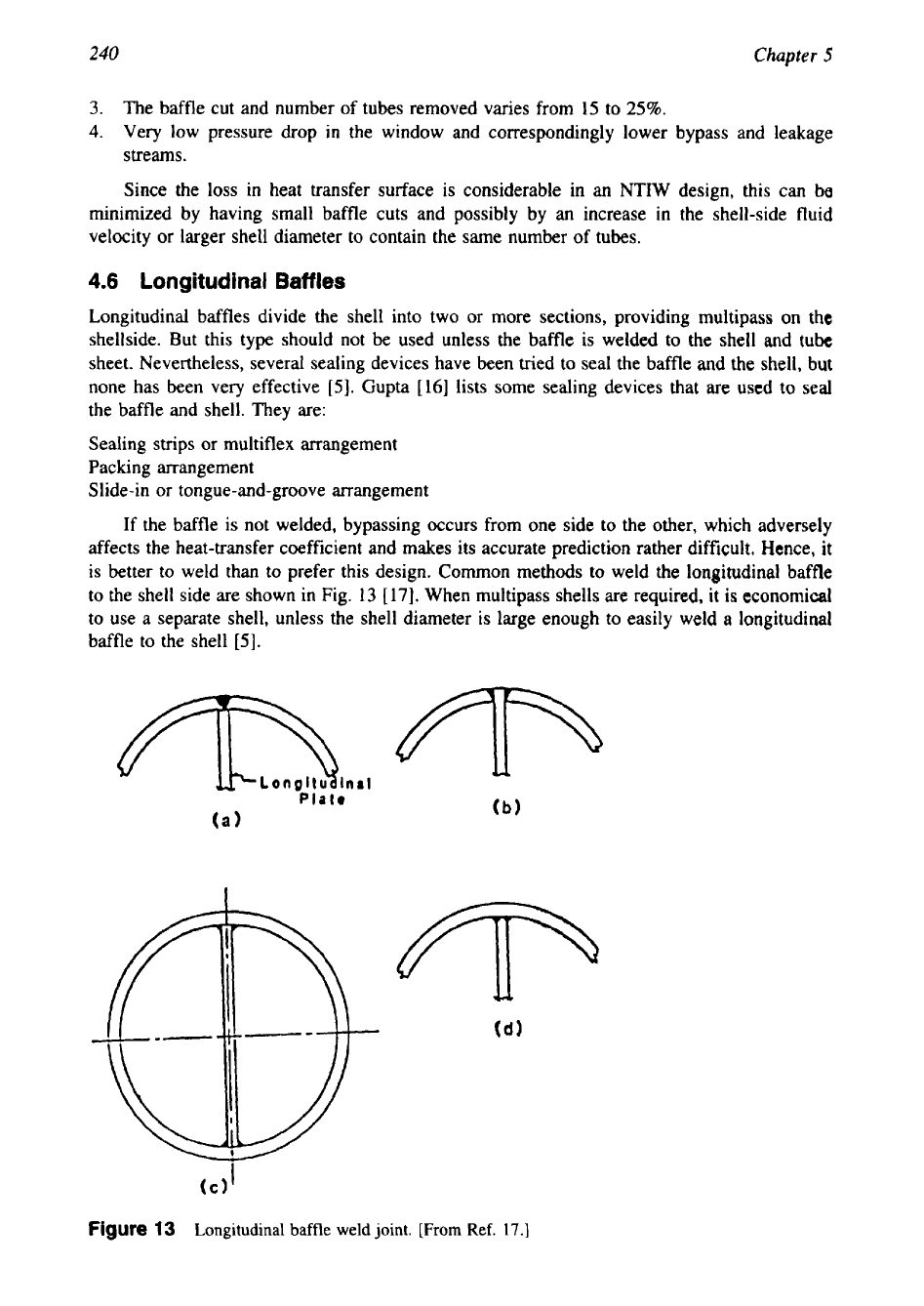
If the baffle is not welded, bypassing occurs from one side to the other, which adversely
affects the heat-transfer coefficient and makes its accurate prediction rather difficult. Hence, it
is better
to
weld than to prefer this design. Common methods to weld the longitudinal baffle
to the shell side are shown
in
Fig. 13 [17]. When multipass shells are required, it
is
economical
to use a separate shell, unless the shell diameter is large enough to easily weld
a
longitudinal
baffle to the shell [5].
I
(C)
Figure
13
Longitudinal
baffle
weld joint.
[From
Ref.
17.1
241
Shell and
Tube
Heat Exchanger Design
h
A
A
TYP
for
alt
strip
to
ring
junctions
slde
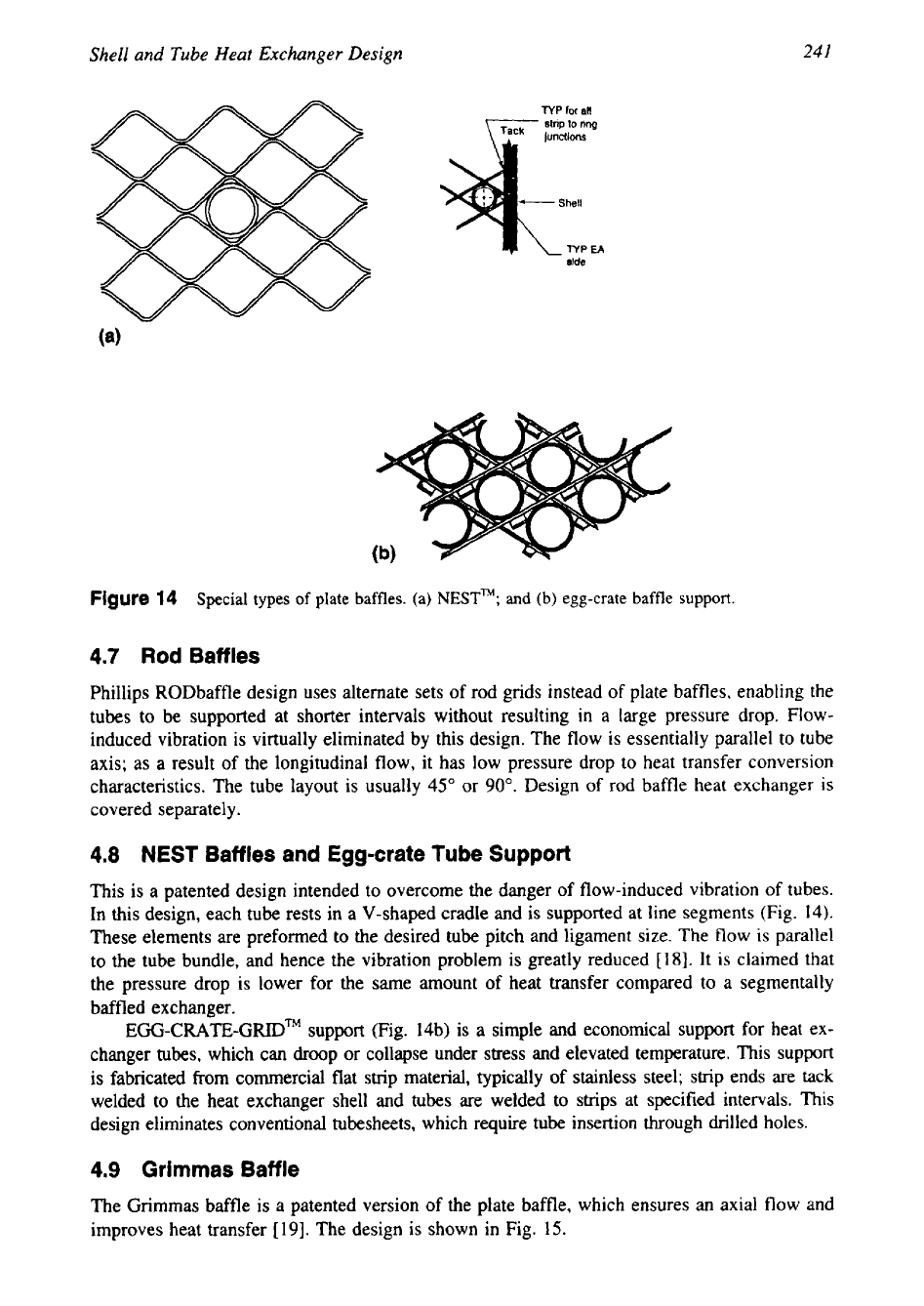
Figure
14
Special types of plate baffles. (a)
NESTTM;
and
(b) egg-crate baffle support.
4.7
Rod Baffles
Phillips RODbaffle design uses alternate sets of rod grids instead
of
plate baffles, enabling the
tubes to be supported at shorter intervals without resulting in a large pressure drop. Flow-
induced vibration is virtually eliminated by this design. The flow is essentially parallel to tube
axis; as
a
result of the longitudinal flow, it has low pressure drop to heat transfer conversion
characteristics. The tube layout is usually
45"
or
90".
Design
of
rod baffle heat exchanger
is
covered separately.
4.8
NEST
Baffles
and
Egg-crate Tube Support
This is a patented design intended to overcome the danger of flow-induced vibration of tubes.
In this design, each tube rests in a V-shaped cradle and is supported at line segments (Fig.
14).
These elements are preformed to
the
desired tube pitch and ligament size. The flow
is
parallel
to the tube bundle, and hence the vibration problem
is
greatly reduced
[
181.
It is claimed that
the pressure drop is lower for the same amount
of
heat transfer compared to a segmentally
baffled exchanger.
EGG-CRATE-GRIDTM
support (Fig. 14b) is
a
simple and economical support for heat ex-
changer tubes, which can droop or collapse under stress and elevated temperature. This support
is fabricated from commercial flat strip material, typically of stainless steel; strip ends are tack
welded to the heat exchanger shell and tubes are welded to strips at specified intervals. This
design eliminates conventional tubesheets, which require tube insertion through drilled holes.
4.9
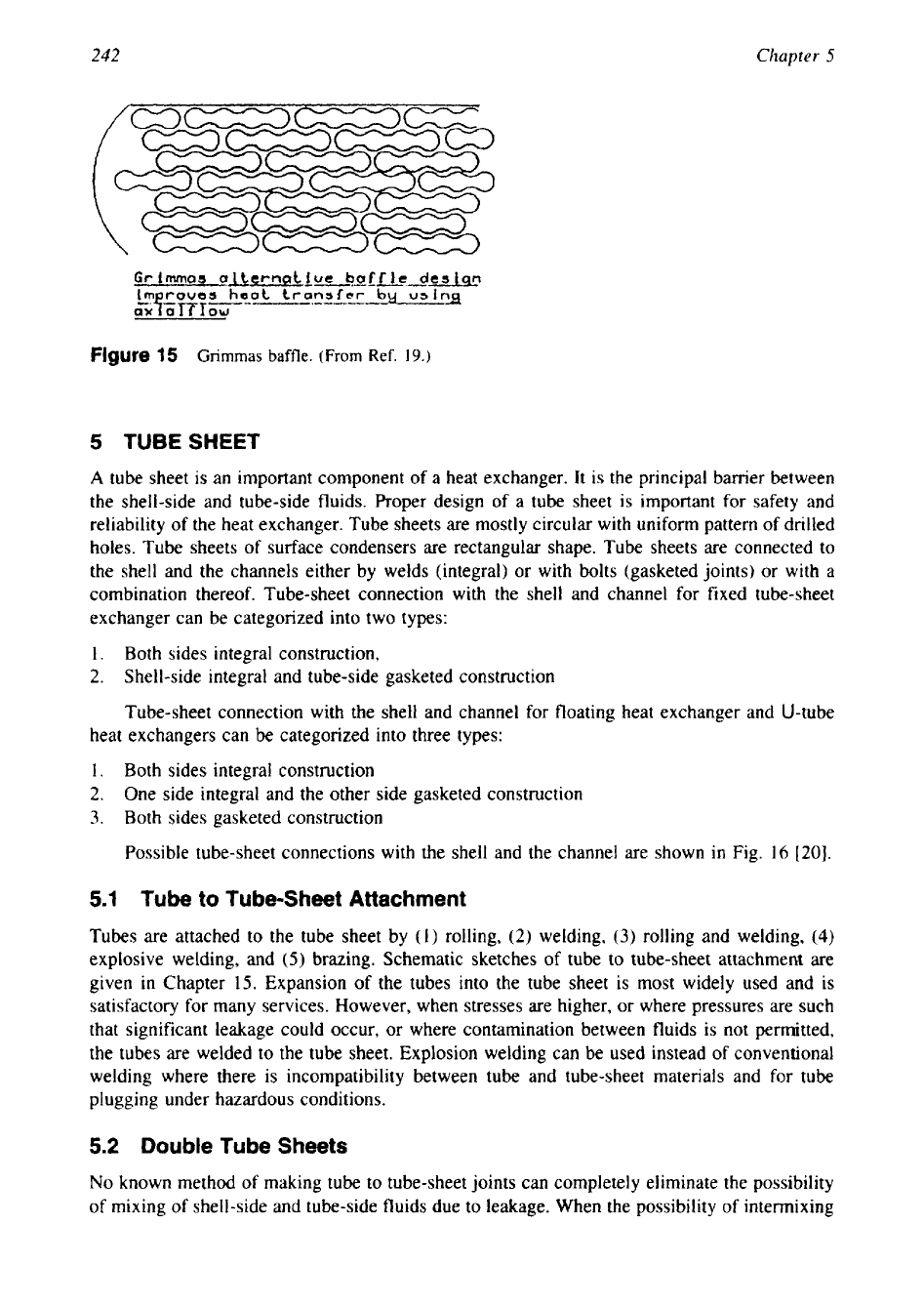
Grimmas Baffle
The Grimmas baffle is a patented version of the plate baffle, which ensures
an
axial
flow
and
improves heat transfer
[19].
The design is shown in Fig.
15.
242
Chapter
5
Figure
15
Grimmas
baffle. (From
Ref.
19.)
5
TUBESHEET
A
tube sheet is an important component of a heat exchanger. It is the principal barrier between
the shell-side and tube-side fluids. Proper design of a tube sheet is important
for
safety and
reliability of the heat exchanger. Tube sheets are mostly circular with uniform pattern of drilled
holes. Tube sheets of surface condensers are rectangular shape. Tube sheets are connected to
the shell and the channels either by welds (integral)
or
with bolts (gasketed joints)
or
with a
combination thereof. Tube-sheet connection with the shell and channel for fixed tube-sheet
exchanger can be categorized into two types:
1. Both sides integral construction,
2.
Shell-side integral and tube-side gasketed construction
Tube-sheet connection with the shell and channel for floating heat exchanger and U-tube
heat exchangers can be categorized into three types:
1.
Both sides integral construction
2.
One side integral and the other side gasketed construction
3.
Both sides gasketed construction
Possible tube-sheet connections with the shell and the channel are shown in Fig.
16
[20].
5.1
Tube to Tube-Sheet Attachment
Tubes are attached to the tube sheet by
(1)
rolling,
(2)
welding,
(3)
rolling and welding,
(4)
explosive welding, and
(5)
brazing. Schematic sketches of tube to tube-sheet attachment are
given
in
Chapter
15.
Expansion
of
the tubes into the tube sheet is most widely used and is
satisfactory for many services. However, when stresses are higher,
or
where pressures are such
that significant leakage could occur, or where contamination between fluids is not permitted,
the tubes are welded to the tube sheet. Explosion welding can be used instead of conventional
welding where there
is
incompatibility between tube and tube-sheet materials and
for
tube
plugging under hazardous conditions.
5.2
Double Tube Sheets
No
known method
of
making tube to tube-sheet joints can completely eliminate the possibility
of mixing
of
shell-side and tube-side fluids due to leakage. When the possibility
of
intermixing

243
Shell and
Tube
Heat Exchanger Design
Figure
16
Tubesheet connection
with
shell and channel. (Note:
2
and
4
refer to
fixed
tubesheet design.)
of the shell-side and tube-side fluids cannot
be
tolerated, double tube-sheet construction will
offer positive assurance against one fluid leaking into the other at a tube to tube-sheet joint.
Types of Double Tube-Sheets Designs
Two designs of double tube sheets are available:
(I)
the conventional double tube sheet design,
which consists of two individual tube sheets at each end of the tubes, and
(2)
the integral
double tube-sheet design
[2
I].
Conventional Double Tube Sheet Design
In a conventional double tube-sheet design, the tube sheets are installed with a small space
between them. The space is usually open to the atmosphere. Sometimes a thin strip is welded
to avoid ingress of dusts and dirt, or an expansion joint
is
welded with vent at the top and a
drain at the bottom. These patterns are shown in Fig.
17.
While selecting material for double
tubesheet design, the outer tubesheet should be compatible with the tubeside fluid and the
inner tubesheet should be compatible with the shellside fluid. The most important consideration
is the differential radial expansion
of
the two tubesheets which will stress the tubes. The double
tube sheet can be installed only in the U-tube, fixed tube sheet, and floating head, outside
packed stuffing box exchangers. It is not feasible to use the double tube sheet in heat exchanger
types such as
[4]
(1)
floating head, pull-through bundle,
(2)
floating head with split backing
ring, and
(3)
floating head, outside packed lantern ring exchangers. An expression for the space
between the tubesheets pairs,
l,,
which is widely used in the industry
is
a special case of the
more complex analysis of Urgami et al.
[22].
The expression is given by [21]: