Kuppan T. Heat Exchanger Design Handbook
Подождите немного. Документ загружается.

204
Chapter
4
A,
=
tr
(re
-
To)
(93)
Substituting the values of
p
and
$
in
Eq.
90, the resulting formula for
fin
efficiency is
giv-
en
by
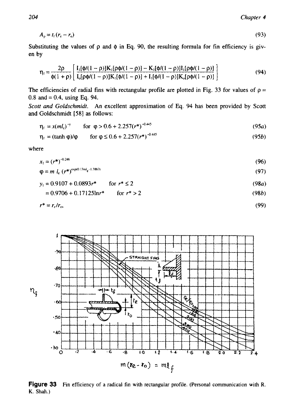
The efficiencies
of
radial fins with rectangular profile are plotted
in
Fig.
33
for values of
p
=
0.8
and
=
0.4,
using
Eq.
94.
Scott and Goldschmidt.
An excellent approximation
of
Eq.
94
has been provided
by
Scott
and
Goldschmidt [58] as follows:
qf
=
x(mfe)-'
for
(p
>
0.6
+
2.257(r*)4.a5
qf
=
(tanh
cp)/(p
for
(p
5
0.6
+
2.257(~-*)-(',#~
where
yI
=
0.9107
+
0.0893F
for
F
5
2
=
0.9706
+
0.17 1251nr*
for r*
>
2
r*
=
r,/r,,
(99)
Figure
33
Fin efficiency
of
a radical fin with rectangular profile. (Personal communication with
R.
K.
Shah.)
205
Compact Heat Exchangers
Schmidt Method.
The Schmidt
[59]
formula for the efficiency of a plane circular fin is giv-
en by
tanh
ml*
q=-----
ml*
where
I*
is given by
in which
p
=
re/ro.
It was shown that for
0.5
I
p
I
1
and
1
I
p
5
8,
the error using Eq.
101
is
less than
1%
of the exact value of the
fin
efficiency. Because the
fin
efficiency is very close
to unity for typical low-finned tube geometries, Rabas and Taborek
[7]
do not recommend any
corrections to this method to account for departure from a rectangular profile and for the
nonuniformity of the heat-transfer coefficient over the height of the fin.
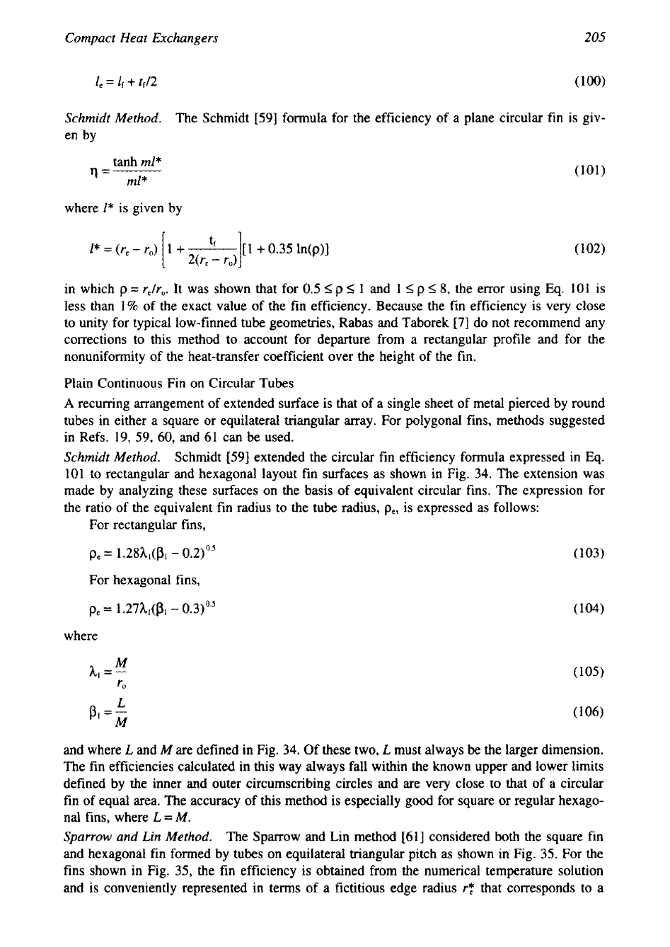
Plain Continuous Fin on Circular Tubes
A
recurring arrangement of extended surface is that of a single sheet
of
metal pierced by round
tubes in either a square or equilateral triangular array. For polygonal fins, methods suggested
in Refs.
19,
59,
60,
and
61
can
be
used.
Schmidt Method.
Schmidt
[59]
extended the circular
fin
efficiency formula expressed
in
Eq.
101
to rectangular and hexagonal layout
fin
surfaces as shown in Fig.
34.
The extension was
made by analyzing these surfaces on the basis of equivalent circular fins. The expression for
the ratio of the equivalent fin radius to the tube radius,
p,,
is expressed as follows:
For rectangular fins,
For hexagonal fins,
where
M
h,
=-
ro
PI
=-
L
M
and where
L
and
M
are defined in Fig.
34.
Of these two,
L
must always be the larger dimension.
The fin efficiencies calculated in this way always fall within the known upper and lower limits
defined by the inner and outer circumscribing circles and are very close to that of
a
circular
fin of equal area. The accuracy
of
this method is especially good for square or regular hexago-
nal fins, where
L
=
M.
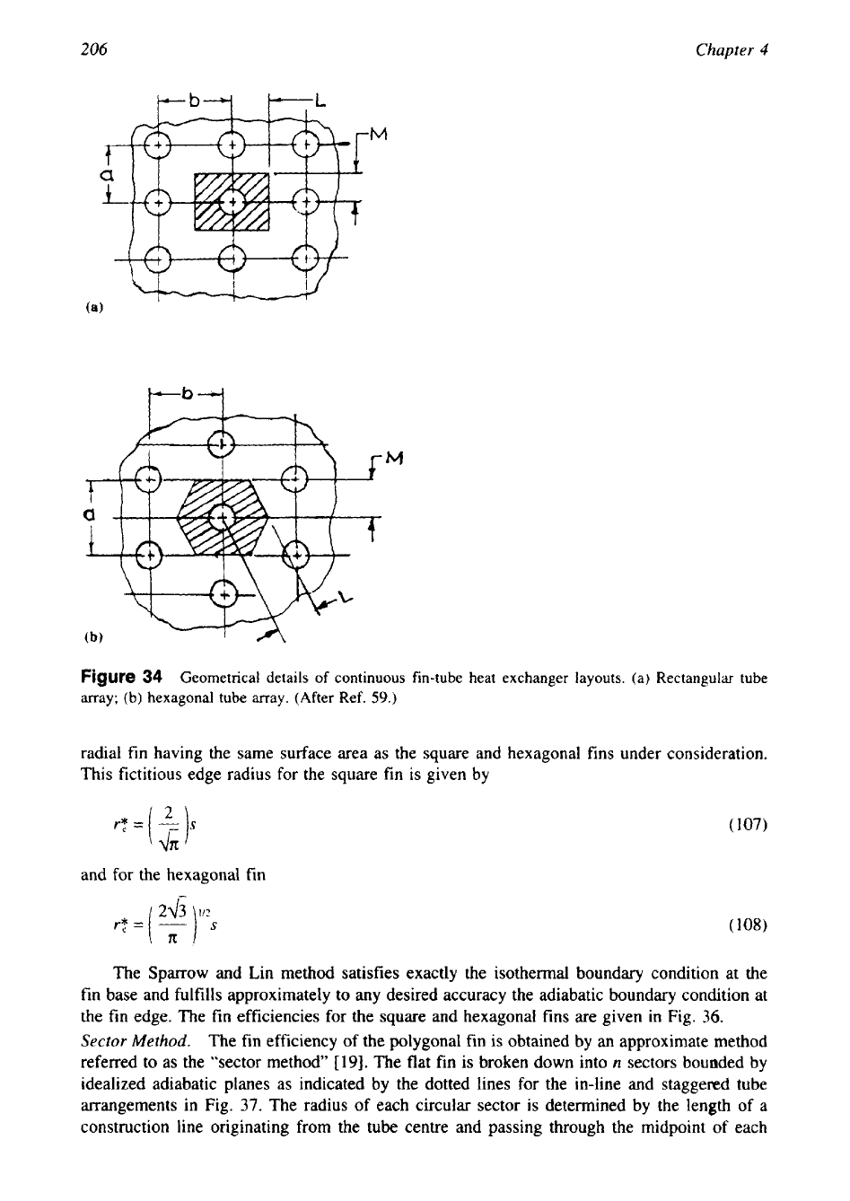
Sparrow
and Lin Method.
The Sparrow and Lin method
[61]
considered both the square
fin
and hexagonal fin formed by tubes on equilateral triangular pitch as shown in Fig.
35.
For the
fins shown in Fig.
35,
the
fin
efficiency is obtained from the numerical temperature solution
and is conveniently represented in terms of a fictitious edge radius
rT
that corresponds to a
206
Chapter
4
M
f
Figure
34
Geometrical details of continuous fin-tube heat exchanger layouts. (a) Rectangular
tube
array; (b) hexagonal tube array. (After Ref.
59.)
radial
fin
having the same surface area as the square and hexagonal fins under consideration.
This fictitious edge radius for the square
fin
is given by
and for the hexagonal fin
rT=(y]
I/?
s
2+
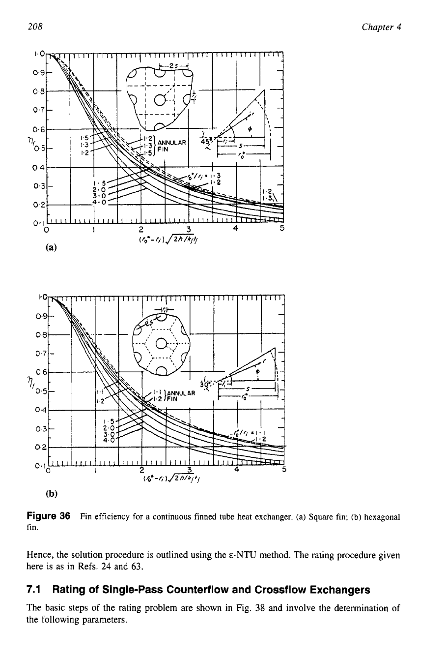
The Sparrow and Lin method satisfies exactly the isothermal boundary condition at the
fin base and fulfills approximately to any desired accuracy the adiabatic boundary condition at
the fin edge. The
fin
efficiencies for the square and hexagonal fins are given
in
Fig.
36.
Sector
Method.
The fin efficiency of the polygonal fin is obtained by
an
approximate method
referred to as the “sector method”
[19].
The flat fin is broken down into
n
sectors bounded by
idealized adiabatic planes as indicated by the dotted lines for the in-line and staggered tube
arrangements in Fig. 37. The radius of each circular sector is determined by the length
of
a
construction line originating from the tube centre and passing through the midpoint of each
207
Compact Heat
Exchangers
Figure
35
Fictitious edge radius
for
unit
fin
surface
of
continuous fin with circular tube. (a) Square
layout
(i.e.,
square fin);
(b)
staggered layout (30") (Le., hexagonal fin).
line segment. The fin efficiency of each sector is then determined by use of
Eq.
94,
95,
or
101.
The fin efficiency for the entire surface can then be determined by the summation as
where
Af.,
is the area of each
fin
sector. The approximation improves as
n
becomes very large,
but for practical purposes, only a few segments will suffice to provide
Of
within a desired
accuracy of
0.1%.
The
fin
efficiency calculated by the sector method is lower than that for the
actual flat fin, whereas the equivalent annulus method yields
0,
values that are higher than
those by the sector method for highly rectangular fin geometry around the tubes
[
191.
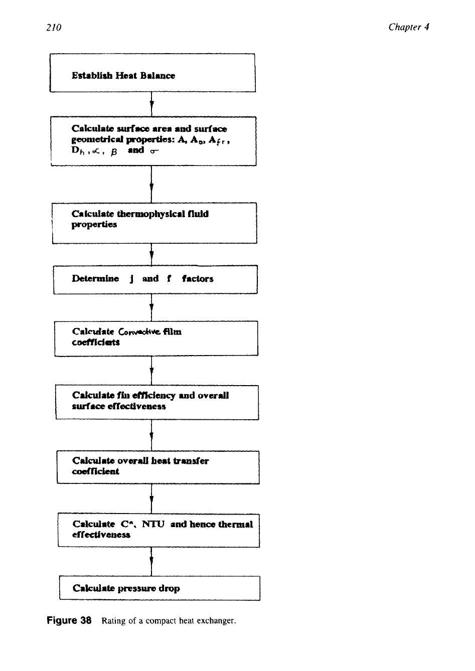
7
RATING OF
A
COMPACT EXCHANGER
The rating problems for a two-fluid direct transfer type compact crossflow and counterflow
exchanger with gas as a working fluid at least
on
one side is discussed in this section. The
surface employed on the gas side of this exchanger has a high surface area density and
low
hydraulic diameter. Customarily, the E-NTU method is employed for compact heat exchangers.
208
Chapter
4
Figure
36
Fin efficiency for a continuous finned tube heat exchanger. (a) Square fin;
(b)
hexagonal
fin.
Hence, the solution procedure is outlined using the E-NTU method. The rating procedure given
here is as in Refs.
24
and
63.
7.1
Rating of Single-Pass Counterflow and Crossflow Exchangers
The basic steps of the rating problem are shown in Fig.
38
and involve the determination of
the following parameters.

209
Compact Heat Exchangers
Figure
37
Fin sectors to determine fin efficiency of continuous finned tube heat exchanger.
1.
Surface geometrical properties. These include
A,,
minimum free flow area
A,
heat-transfer surface area (total of primary surface area,
A,,
and secondary surface
area,
A,)
L,
flow length
Dh,
hydraulic diameter
p,
heat-transfer surface area density
0,
ratio of minimum free flow area to frontal area
lf,
fin length
tf,
fin thickness
Also included are specialized dimensions used for heat-transfer and pressure-drop correla-
tions.
2.
Fluid physical properties. Determine the thermophysical properties at bulk mean tempera-
ture for each fluid, namely, hot and cold fluids. The properties needed for the rating
problem are
p,
c,,
k,
and Pr. Since the outlet temperatures are not known for the rating
problem, they are guessed initially. Unless it is known from the past experience, assume
an exchanger effectiveness as
60-75%
for most single-pass crossflow exchangers, and
80-85%
for single-pass counterflow and two-pass cross-counterflow exchangers. For the
assumed effectiveness, calculate the fluid outlet temperatures by
210
Chapter
4
Establish
Heat
Balance
c
Calculate
surface
area
and
surface
geometrical
praperties:
A,
A,,,
Afr
,
Dhd,
p
and
0-
I
Calculate
thermophysicrl
fluid
properties
t
1
Determine
j
and
f
factors
I
t
Calculate
CO&*
film
caeffidats
I
Calculate
fh
e~ciency
and
overall
surface
effectiveness
Calculate
overall
heat
transfer
uwfkient
Calculate
CA,
NTU
and
hence
thermal
cffectivaesa
t
I
Calculate
pressure
drop
I
Figure
38
Rating
of
a compact heat exchanger.
Compact Heat Exchangers
21
I
Initially, assume
cc/ch
==
kf,/Mh for a gas-to-gas exchangers, or
cc/ch
=
(kfcp),/(kfcp)h
for
a gas-to-liquid exchanger with approximate values of
c,s.
For exchangers with
C*
2
0.5
(usually gas-to-gas exchangers), the bulk mean temperature on each side will be the
arithmetic mean
of
the inlet and outlet temperatures on each side. For exchangers with
C*
<
0.5
(usually gas-to-liquid exchangers), the bulk mean temperature
is
calculated as
given in Table
2.
Once the bulk mean temperatures are obtained on each side, obtain the fluid proper-
ties from thermophysical property tables or from standard thermal engineering books.
3.
Reynolds numbers. Calculate the Reynolds number and/or any other pertinent dimension-
less groups needed to determinej or Nu and
f
of heat-transfer surfaces on each side
of
the exchanger.
4.
Computej or
Nu
and
f
factors.
5.
Correct Nu (or
j)
and
f
for variable fluid property effects in the second and subsequent
iterations.
6.
From Nu or
j,
determine heat-transfer coefficient for both the fluid streams,
h=-
Nuk
(1
12a)
Dh
or
h
=jG
C$rZ'3
(1
12b)
7.
Determine the fin efficiency
qf
and the overall surface efficiency
q,
given by
tanh
ml
rlf
=-
ml
8.
Overall conductance. Calculate the wall thermal resistance,
Rw.
Knowing the fouling re-
sistances Rf,h and Rf,,on the hot and cold fluid sides, respectively, calculate the overall
thermal conductance
UA
from
(1
15a)
Table
2
Approximate Bulk Mean Temperature
on
the
Hot
and
Cold
Side
of
a
Two-Fluid Heat Exchanger
for
c*
<
0.5
[24,63]
C,,,
=
hot fluid
C,,
=
cold fluid
C,,,
=
cold fluid
C,,,
=
hot
fluid
212
Chapter
4
9.
Calculate NTU,
C*,
and exchanger effectiveness,
E.
If the thermal effectiveness is above
80%,
correct for wall longitudinal conduction effect.
10.
Compute the outlet temperature from
Eqs.
110 and 11
1.
If these outlet temperatures
differs significantly from those assumed in step 2, use these outlet temperatures in step
2 and continue iterating steps
2-9
until the assumed and computed outlet temperatures
converge within the desired degree of accuracy. For a gas-to-gas exchanger probably one
or two iterations will be sufficient.
11.
Compute the heat duty from
12.
Calculate the core pressure drip. The friction factor
f
on each side is corrected for
the
variable fluid properties as discussed in Chapter
3.
The wall temperature
T,
is
computed
from
7.2
Shah’s Method for Rating of Multipass Counterflow and
Crossflow Heat Exchangers
The rating procedure for multipass crossflow exchangers with fluids mixed between passes
is
described by Shah [63]. The solution procedure for rating problem for the two-pass crossflow
exchangers with flows unmixed in the passes but mixed between passes is also very similar to
the sizing of single-pass crossflow. Only some
of
the calculations on the two pass side need
to be modified, and only those points are summarized here.
1. In order to compute fluid bulk mean temperature and thermophysical properties of fluids,
first guess the overall thermal effectiveness,
eN.
Assume it to be
8045%
unless it is known
from the past experience. .Assume that the NTU per pass is same. The individual pass
effectiveness
E,
is related to overall effectiveness for the case
of
fluids mixed between
passes. Compute approximate values of
ce
and
ch
since we don’t know yet the accurate
values of the specific heats.
2. Determine the intermediate and outlet temperature by solving the following individual pass
effectiveness and overall effectiveness equations:
In the foregoing three equations there are three unknowns:
t,.,,
tc,lnl,
and
th,lnt.
Hence, they
can be evaluated exactly and then from the overall energy balance
t,,,
is calculated.
Since we know all terminal temperatures for each pass, we can determine the bulk mean
temperature for each fluid
in
each pass and subsequently the fluid properties separately for
each pass.
Compact Heat Exchangers
213
8 SIZING
OF
A
COMPACT HEAT EXCHANGER
The basis of sizing involves coupling of heat transfer and flow friction in the derivation of the
core mass velocity
G
on each side of a two fluid exchanger. Subsequently, the sizing problem
is carried out in a manner similar to the rating problem.
8.1
Core Mass Velocity Equation (after Shah
[24])
The dominant term in the expression for the pressure drop is the core friction term. The en-
trance and exit effects are generally relatively small and are of the opposite sign. Similarly,
the flow acceleration term is relatively small in most heat exchangers, being generally less
than
10%
of the core friction term [24],
so
their elimination is usually warranted in a first
approximation. With these approximations and Ldrh
=
AIA,,
the expression for pressure drop
may be written after rearrangement as
In the absence of fouling resistances, the overall NTU is related to NTUh, NTU,, and the wall
resistance, R,, by
The wall resistance term is generally small and hence neglected in the first-approximation
calculation. Hence, the number of transfer units
on
one side of interest (either hot or cold),
designated as NTUI, may be estimated from the known overall NTU as given next.
If both fluids are gases, one can start with the estimate that the design is “balanced” by a
selection of the hot and cold side surfaces
so
that Rh
=
R,
=
RJ2,
that
is,
NTUh
=
NTU,
=
2NTU.
Then
NTUI
=
NTU2
=
2NTU
(
126)
For a gas-liquid heat exchanger, one might estimate
NTUgas
side
=
1
-
1
(m)
(127)
The term NTU, is related to the Colburn factor
j
on side
1
by
Eliminating
(AIA,)
from
Eqs.
124 and
128,
and simplifying the expression, we get the core
mass velocity G for one side:
The feature that makes this equation
so
useful is that the ratiojlfis a relatively flat function
of the Reynolds number. Thus one can readily estimate an accurate magnitude of
jlf
based on
a “ballpark” estimate of
Re.
If there are no fins, overall surface efficiency
q,
=
1.
For a “good
design,” the fin geometry is chosen such that
qo
is in the range
70-90%.
Therefore
qo
=
0.8
is
suggested as a first approximation to determine
G
from Eq.
129.
8.2
Procedure for Sizing
a
Compact Heat Exchanger
The procedure for sizing any of the compact heat exchangers (Fig.
39)
is almost inevitably an
iterative one and thus lends itself very conveniently to computer calculations. Kays and London