Kuppan T. Heat Exchanger Design Handbook
Подождите немного. Документ загружается.

224
Chapter
4
reduce the amount of recirculation, windwalls may be erected along the periphery of the heat
exchanger. This problem has been analyzed experimentally and numerically by Kroger
[67],
Analysis shows that the effectiveness of heat exchanger can be expressed approximately
by
[67]:
where
H
and
W
are shown in Fig.
44,
Hw
is the windwall height,
V,
is the plume velocity
immediately after the heat exchanger, and paand
po
are the inlet and outlet
air
densities respec-
tively. To reduce the amount of recirculation, high windwalls may be erected along the
periph-
ery of the heat exchanger.
10.6
Design
Aspects
Proper design of air-cooled heat exchangers for cold climate service requires a well-balanced
consideration
of
fluid flow, heat transfer, structural design, air movement, wind effects, temper-
ature control in cold climate, and economics
1731.
Design of air-cooled heat exchangers
is
detailed by Paikert
[31],
Ganapathy
[68],
Brown
[74],
and Sunders
[75],
and
Mukherjte
[76,77
J.
Design Variables
Modem air-cooled heat exchanges are designed thermally by computers, which
arc
capable
of
examining all design variables to produce the optimum unit. In view of the increased
size
and
cost of these units in large plants and the competitive nature of the industry, improved
md
more sophisticated designs are essential to satisfy the needs of the industry
and
the society
[67].
Important design variables pertaining to the tube bundle include
Tube (diameter, length and wall thickness, number of tube rows)
Fins (height, spacing, thickness)
Space (length, width, and depth)
Designers usually optimize criteria such as
[78]:
Capital versus running cost
Forced versus induced draft fan
Type and spacing of fins
Number
of
tube rows
Fan design and noise level
Air Velocity
If the air
flow
rate is known, the tentative
air
velocity may be chosen, which establishes the
cooler face area. In air-cooled heat exchanges, face velocity
is
usually
in
the
range
of
1.5-4
m/s
[75].
Face velocity is based on the gross cross-sectional
area
for
air
flow
(€we area), as
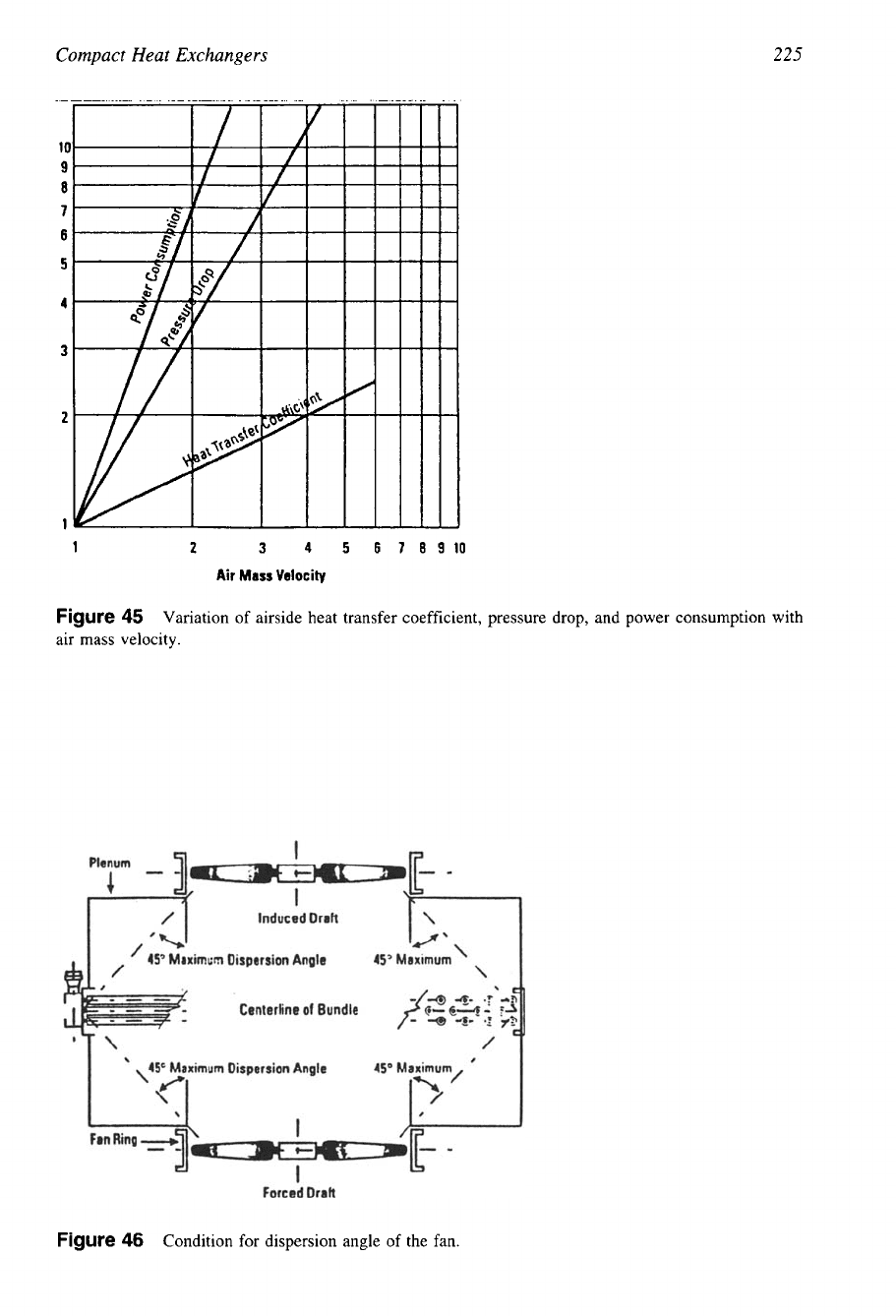
though the tubes were absent. Variation of airside heat to coefficient,
pressure
drop,
and power
consumption with air mass velocity is shown in Fig.
45.
Air-Side Pressure Losses, Fan Power, and Noise
The total air-side pressure loss is the sum of pressure loss
through
the
finned-tube bundle and
the pressure loss due to the fan and plenum. Bundle pressure loss
is
calculated from makers’
test data
or
correlations.
225
1
Compact Heat Exchangers
2
3
4
5
6
78910
Air
Mass
Velocity
Figure
45
Variation of airside heat transfer coefficient, pressure drop, and power consumption with
air mass velocity.
Figure
46
Condition for dispersion angle of the fan.
226
Chapter
4
Capital Versus Running Cost
A total cost evaluation usually consists of the following four elements [79]:
1. Project equipment cost
2.
Field installation cost
3.
Electrical distribution cost
4.
Operating cost
Air cooler costs are influenced by the type of air-side flow and the temperature control
requirements. Those process fluids that do not require controlled outlet temperature and do not
have freeze problems require minimal air flow control [77]. Consider the preferred drive and
cost of horsepower, and the payback time for balancing capital investment for adding surface
area, against operating costs of fan horsepower.
Design Air Temperature
The following data are needed for realistic estimates of the design air temperature
[68]:
An annual temperature probability curve
Typical daily temperature curves
Duration frequency curves for the occurrence of the maximum dry-bulb temperature
Air Cooler Design Procedure
Preliminary Sizing
by
Brown’s
Method.
Once the inlet temperature is known, a reliable first
approximation of the cooler design may be obtained. There are several short-cut manual meth-
ods available in the literature. One such method is that of Brown [74]. Brown considers his
method will establish a size within
25%
of optimum. The method can be stated by the follow-
ing simple steps:
First, an overall heat-transfer coefficient is assumed, depending on the process fluid and
its temperature range. Approximate overall heat transfer coefficient, for air cooled heat ex-
changers are tabulated in Ref. 74.
Second, the air temperature rise
(tl
-
t,)
is calculated by the following empirical formula:
T,+&
t.
-
t,
=
O.oO5U
(
-
t,]
(135)
where
T,
and
T2
are hot process fluid terminal temperatures.
Third, the estimate is based on bare tubes, with a layout and fan horsepower estimated
from that,
so
as to avoid the complexity of fin types. Approximate bare tube surface versus
unit sizes are tabulated in Ref. 74.
Sizing.
The procedure to follow in air cooler design includes the following steps:
1.
Specify process data and identify site data.
2.
Assume the layout of the tube bundle (from preliminary sizing), fin geometry, and air
temperature rise.
3.
Calculate film coefficients and overall heat-transfer coefficient, mean temperature differ-
ence and correction
F,
and surface area. Check this surface against the assumed layout.
4.
If the required surface matches with the assumed layout, calculate the tube-side pressure
drop and verify with the specified value.
5.
If the surface area and tube-side pressure drop are verified, calculate the air-side pressure
drop and fan horsepower.
Compact Heat Exchangers
227
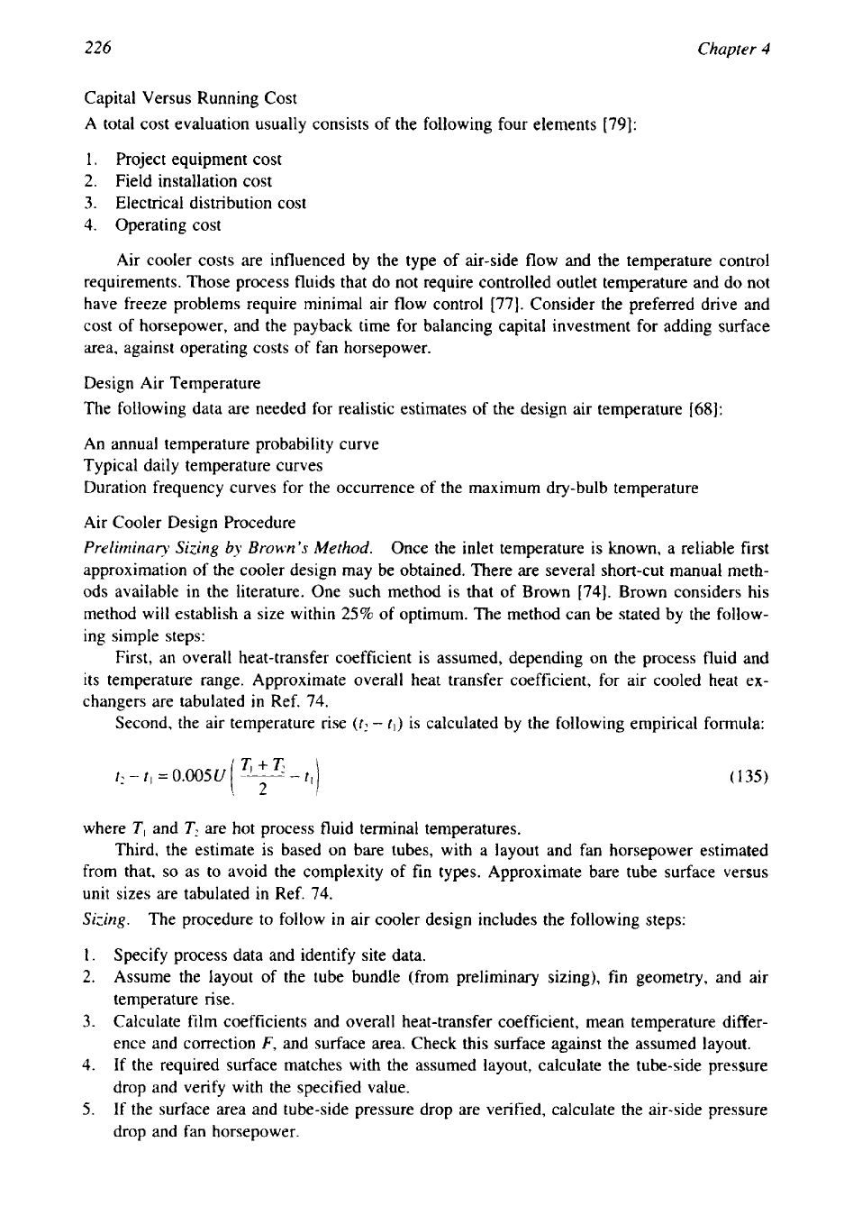
Air Cooler Data Sheet
An air-cooled heat exchanger data sheet is shown in Fig. 47. It should be submitted to the
vendor along with the job “specific requirements” as follows [72]:
1.
Location of the plant and elevation above sea level
2.
Location
of
the unit in the plant
3.
Temperature variation due to weather conditions
4.
Seismic and wind loads
5.
Variations in operation
6.
Process control instrumentation
7.
Fire protection
1
a
a
4
I
e
’1
8
m
10
11
12
13
14
1s
*a
17
11
1s
a0
21
22
2J
24
2s
U
39
40
41
42
43
44
45
46
47
48
48
Ap9r0u.d:
OM@:
Rw.
Ra
.
RW.
Figure
47
ACHE
data
sheet.

228
Chapter
4
Prondtl
number
!
I
c
.-.
I
5
1
I
I
3
I
I
I
I
I
Lominor
llM
-
,
I
-
turbulmt
flow
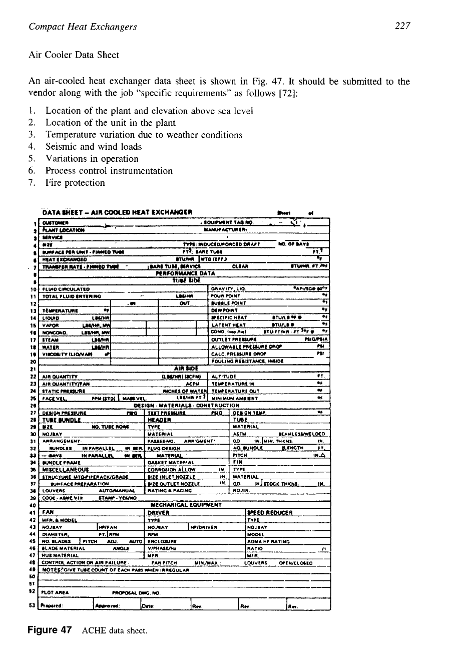
Figure
48
Typical relationship between
Colburn
j
factor and Reynolds number.
8.
Pumping power
9.
Special surface finish
The variation
of
airside heat transfer coefficient, pressure
drop,
and power consumption
with air mass velocity is shown in Fig.
45.
The condition for dispersion angle
of
the fan is
shown in Fig.
46.
Typical relationship between Colburnj factors
and
Reynolds number is shown in Fig.
48.
5
Shell
and
Tube
Heat
Exchanger
Design
The most commonly used heat exchanger is the shell and tube type. It is the “workhorse” of
industrial process heat transfer. It has many applications in the power generation, chemical,
and process industries. Other types of heat exchangers are used when economical. Though the
application of other types of heat exchangers is increasing, the shell and tube heat exchanger
will continue its popularity for a long time, largely because of its versatility
[
11.
1
CONSTRUCTION DETAILS
FOR
SHELL
AND
TUBE
EXCHANGERS
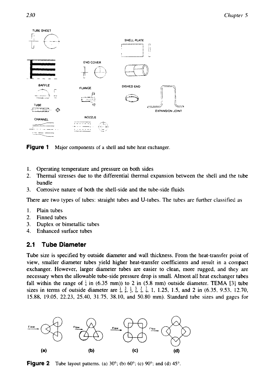
The major components of a shell and
tube
exchanger are tubes, baffles, shell, front head, rear
head, tube sheet(s), and nozzles. Expansion joint is an important component in the case
of
fixed tube-sheet exchanger for certain design conditions. The selection criteria for a proper
combination of these components are dependent upon the operating pressures, temperatures,
thermal stresses, corrosion characteristics of fluids, fouling, cleanability
,
and cost. Other com-
ponents include nozzles and supports. Expansion joints, nozzles, and supports are discussed in
Chapter
11,
Mechanical Design
of
Shell and Tube Heat Exchangers.
A
large number of geo-
metrical variables are associated with each component and they are discussed in detail in this
chapter. Major components
of
shell and tube heat exchangers are shown in Fig.
1.
2
TUBES
Tubes of circular cross section are exclusively used in exchangers. Since the desired heat
transfer in the exchanger takes place across the tube surface, the selection of tube geometrical
variables is important from the performance point of view
[2].
Important tube geometrical
variables include tube outside diameter, tube wall thickness, tube pitch, and tube layout patterns
(Fig.
2).
Tubes should be able
to
withstand the following:
229
230
Chapter
5
TUBE SHEET
SHELL PLATE
BAFFLE
DISHED END
FLANGE
B
i3-
EXPANSION JOINT
NOZZLE
CHANNEL
/
I I
Figure
1
Major components
of
a shell and tube heat exchanger.
1.
Operating temperature and pressure on both sides
2.
Thermal stresses due to the differential thermal expansion between the shell and the tube
bundle
3.
Corrosive nature of both the shell-side and the tube-side fluids
There are two
types
of tubes: straight tubes and U-tubes. The tubes are further classified
as
1. Plain tubes
2.
Finned tubes
3.
Duplex or bimetallic tubes
4.
Enhanced surface tubes
2.1
Tube
Diameter
Tube size is specified
by
outside diameter and wall thickness. From the heat-transfer point of
view, smaller diameter tubes yield higher heat-transfer coefficients and result in
a
compact
exchanger. However, larger diameter tubes are easier to clean, more rugged, and they are
necessary when the allowable tube-side pressure
drop
is
small.
Almost all heat exchanger tubes
fall within the range of in (6.35 mm)) to
2
in (5.8 mm) outside diameter. TEMA [31 tube
sizes in terms of outside diameter are
i,
i,
:,
i,
$,
i,
1,
1.25, 1.5, and
2
in (6.35, 9.53, 12.70,
15.88, 19.05,
22.23,
25.40,
31.75, 38.10, and 50.80 mm). Standard tube sizes and gages for
Figure
2
Tube
layout patterns. (a)
30";
(b)
60";
(c)
90';
and (d)
45".
Shell and Tube Heat Exchanger Design
231
various metals are given in TEMA Table RCB-2.21. These sizes give the best performance
and are most economical in many applications. Most popular are the ;-in and f-in sizes, and
these sizes give the best all-around performance and are most economical in most applications
[4].
Use in
(6.35
mm) diameter tubes for clean fluids. For mechanical cleaning, the smallest
practical size is
3
in (19.05 mm). Tubes of diameter 1 in are normally used when fouling
is
expected because smaller ones are not suitable for mechanical cleaning, and falling film ex-
changers and vaporizers generally are supplied with
1.5-
and 2-in tubes
[5].
2.2
Tube
Wall
Thickness
The tube wall thickness is generally identified by the Birmingham wire gage (BWG). Standard
tube sizes and tube wall thickness in inches are presented in TEMA Table
RCB-2.21.
Tube
wall thickness must be checked against the internal and external pressure separately, or maxi-
mum pressure differential across the wall. However, in many cases the pressure is not the
governing factor in determining the wall thickness. Except when pressure governs, the wall
thickness is selected on these bases
[6]:
(1)
providing an adequate margin against corrosion,
(2)
fretting and wear due to flow induced vibration,
(3)
axial strength, particularly in fixed
tube-sheet exchangers, (4) standardized dimensions, and
(5)
cost.
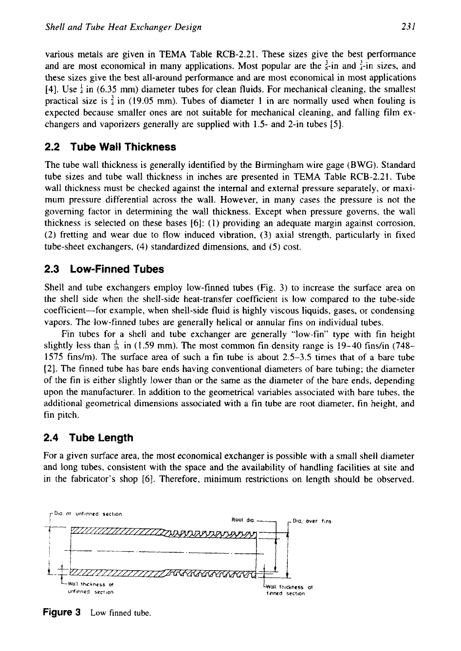
2.3
Low-Finned Tubes
Shell and tube exchangers employ low-finned tubes (Fig.
3)
to increase the surface area on
the shell side when the shell-side heat-transfer coefficient is low compared to the tube-side
coefficient-for example, when shell-side fluid is highly viscous liquids, gases, or condensing
vapors. The low-finned tubes are generally helical or annular fins on individual tubes.
Fin tubes for a shell and tube exchanger are generally “low-fin” type with fin height
slightly less than
&
in (1.59 mm). The most common fin density range is 19-40 findin (748-
1575 fins/m). The surface area of such a fin tube is about
2.5-3.5
times that
of
a bare tube
[2].
The finned tube has bare ends having conventional diameters
of
bare tubing; the diameter
of the fin is either slightly lower than or the same as the diameter
of
the bare ends, depending
upon the manufacturer. In addition to the geometrical variables associated with bare tubes, the
additional geometrical dimensions associated with a
fin
tube are root diameter, fin height, and
fin pitch.
2.4
Tube Length
For a given surface area, the most economical exchanger is possible with a small shell diameter
and long tubes, consistent with the space and the availability of handling facilities at site and
in the fabricator’s shop
[6].
Therefore, minimum restrictions on length should be observed.
Dio.
of
unflnned
sacilon
Root
dio.
I
,Dio.
over
ftns
all
thickness
ot
unfinned sect
Ion
1
tnned
sectton
Figure
3
Low
finned tube.
232
Chapter
5
However, for offshore applications, long exchangers, especially with removable bundles, are
often very difficult to install and maintain economically because of space limitations
[7].
In
this case, shorter and larger shells are preferred despite their higher price per unit heat-transfer
surface. Standard lengths as per TEMA standard RCB-2.1 are 96, 120, 144, 196, and 240 in.
Other lengths may
be
used.
2.5
Means
of
Fabricating Tubes
Tubing used for heat exchanger service may be either welded or seamless. The welded tube
is
rolled into cylindrical shape from strip material and is welded automatically by a precise
joining process.
A
seamless tube may be extruded or hot pierced and drawn. Copper and
copper alloys are available only as seamless products, whereas most commercial metals
are
offered in both welded and seamless. More details on tubing are given in the Chapter 13,
Material Selection and Fabrication.
2.6
Duplex
or
Bimetallic
Tubes
Duplex or bimetallic tubes are available to meet the specific process problem pertaining
to
either the shell side or the tube side. For example, if the tube material is compatible with the
shell-side fluid, but not compatible with the tube-side fluid,
a
bimetallic tube allows it to satisfy
both the corrosive conditions.
2.7
Number
of
Tubes
The number of tubes depends upon the fluid flow rate and the available pressure drop. The
number of tubes is selected such that the tube-side velocity for water and similar liquids range
from
3
to
8
ft/s
(0.9-2.4
m/s) and the shell-side velocity from
2
to
5
ft/s (0.6-1.5 m/s)
[Z].
The lower velocity limit is desired to limit fouling; the higher velocity is limited to avoid
erosion-corrosion on the tube side, and impingement attack and flow-induced vibration on the
shell side. When sand, silt, and particulates are present, the velocity is kept high enough to
prevent settling down.
2.8
Tube Count
To design a shell and tube exchanger, one must
know
the total number of tubes that can fit
into the shell
of
a given inside diameter. This is known as tube count. Factors on which the
tube count depends are discussed in Ref.
6
and in Phadke
[8]
and Whitley et al. [9]. Such
factors include the following:
Shell diameter
Outside diameter of the tubes
Tube pitch
Tube layout pattern-square, triangular, rotated square, or rotated triangular
Clearance between the shell inside diameter and the tube bundle diameter
Type
of
exchanger, i.e., fixed tube sheet, floating head,
or
U-tube
Number of tube-side passes
Design pressure
Nozzle diameter
Tie rods and sealing devices that block space
Type of channel baffle, i.e., ribbon, pie shape, vertical, etc.
[9].
Shell and Tube
Heat
Exchanger Design
233
The conventional method of obtaining tube count by plotting the layout and counting the
tubes (thus the tube count) is cumbersome, time-consuming, and prone to error. Tables of tube
count are available in references like Ref. 10, and Saunders
[
111, Escoe
[
121, and others, which
often cover only certain standard combinations of pitch, tube diameter, and layout parameters.
A
mathematical approach using number theory is suggested by Phadke
[8]
to predict the tube
count and presented tube count for various combinations
of
tube layout parameters. His method
eliminates the disadvantages of drawing the tube layout pattern and can accommodate any
configuration.
2.9
U-Bend Requirements
as
per TEMA
When U-bends are formed, it is normal for the tube wall at the outer radius to thin. As per
TEMA section RCB-2.33, the minimum tube wall thickness in the bent portion before bending
shall be
[3]:
t,=t,
i
I+-
4dRJ
where
t,
is the original tube wall thickness,
t,
the minimum tube wall thickness calculated by
Code rules for a straight tube subjected to the same pressure and metal temperature,
d
the tube
outer diameter, and
Rb
the mean radius of bend.
3
TUBE ARRANGEMENT
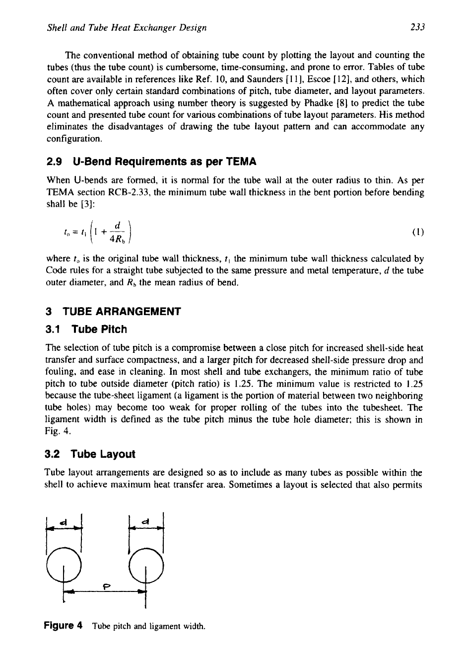
3.1
Tube Pitch
The selection
of
tube pitch is a compromise between a close pitch for increased shell-side heat
transfer and surface compactness, and a larger pitch for decreased shell-side pressure drop and
fouling, and ease in cleaning. In most shell and tube exchangers, the minimum ratio of tube
pitch to tube outside diameter (pitch ratio) is 1.25. The minimum value is restricted to 1.25
because the tube-sheet ligament (a ligament is the portion of material between two neighboring
tube holes) may become too weak for proper rolling
of
the tubes into the tubesheet. The
ligament width is defined as the tube pitch minus the tube hole diameter; this is shown in
Fig.
4.
3.2
Tube Layout
Tube layout arrangements are designed
so
as to include as many tubes as possible within the
shell to achieve maximum heat
transfer area. Sometimes a layout is selected that also permits
Figure
4
Tube
pitch
and ligament width.