Kuppan T. Heat Exchanger Design Handbook
Подождите немного. Документ загружается.

244
Chapter
5
f
Thin-walled
shroud with
w
vent and drain
\Vent above, drain below
Machined
bolt
sleeve spacers
&
Bellows
rOptional shroud
vented and drained
Spacers
are used when the gap
is
too
small
for
separate
channel and the shell flange
bolts.
tack-welded
to
inner tubesheet
(e)
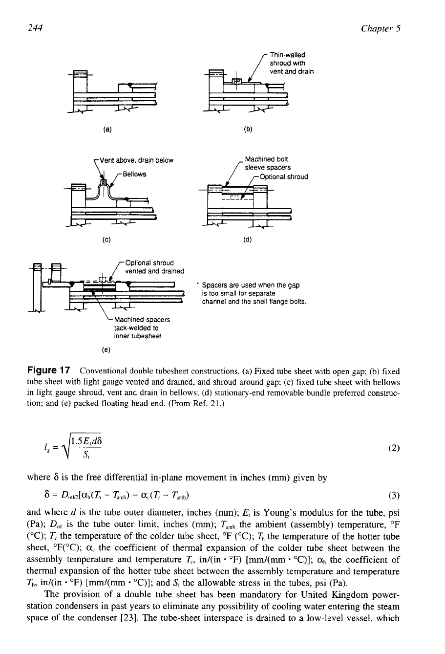
Figure
17
Conventional double tubesheet constructions. (a) Fixed tube sheet with open gap; (b) fixed
tube sheet with light gauge vented and drained, and shroud around gap; (c) fixed tube sheet with bellows
in light gauge shroud, vent and drain in bellows; (d) stationary-end removable bundle preferred construc-
tion; and (e) packed floating head end. (From Ref.
21.)
1.5
E,d6
4
=
dT
where
Ci
is the free differential in-plane movement in inches (mm) given by
and where
d
is the tube outer diameter, inches (mm);
Et
is Young's modulus for the tube, psi
(Pa);
Dot,
is the tube outer limit, inches (mm);
Tamb
the ambient (assembly) temperature,
"F
("C);
T,
the temperature of the colder tube sheet,
"F
("C);
&
the temperature of the hotter tube
sheet,
"F("C);
a,
the coefficient of thermal expansion of the colder tube sheet between the
assembly temperature and temperature
T,,
in/(in
"F)
[mm/(mm
"C)];
ah
the coefficient of
thermal expansion of the hotter tube sheet between the assembly temperature and temperature
Th,
in/(in
OF)
[mm/(mm
"C)];
and
S,
the allowable stress in the tubes, psi (Pa).
The provision of a double tube sheet has been mandatory for United Kingdom power-
station condensers in past years to eliminate any possibility of cooling water entering the steam
space of the condenser
[23].
The tube-sheet interspace is drained to a low-level vessel, which
Shell
and
Tube
Heat
Exchanger
Design
245
is maintained at the condenser absolute pressure by means of a connection to the air pump
suction line.
5.3
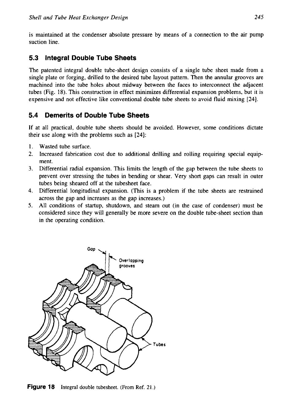
Integral Double Tube Sheets
The patented integral double tube-sheet design consists of a single tube sheet made from a
single plate or forging, drilled to the desired tube layout pattern. Then the annular grooves are
machined into the tube holes about midway between the faces to interconnect the adjacent
tubes (Fig.
18).
This construction in effect minimizes differential expansion problems, but
it
is
expensive and not effective like conventional double tube sheets to avoid fluid mixing
[24].
5.4
Demerits
of
Double Tube Sheets
If at all practical, double tube sheets should be avoided. However, some conditions dictate
their use along with the problems such as
[24]:
1.
Wasted tube surface.
2.
Increased fabrication cost due to additional drilling and rolling requiring special equip-
ment.
3.
Differential radial expansion. This limits the length of the gap between the tube sheets to
prevent over stressing the tubes in bending or shear. Very short gaps can result in outer
tubes being sheared off at the tubesheet face.
4.
Differential longitudinal expansion. (This is a problem if the tube sheets are restrained
across the gap and increases as the gap increases.)
5.
All conditions of startup, shutdown, and steam out (in the case of condenser) must be
considered since they will generally be more severe on the double tube-sheet section than
in the operating condition.
Tubes
Figure
18
Integral double tubesheet. (From Ref.
21.)
246
Chapter
5
6
TUBEBUNDLE
A tube bundle is an assembly of tubes, baffles, tube sheets, spacers and tie rods, and longitudi-
nal baffles, if any. Spacers and tie rods are required for maintaining the space between baffles.
Refer to TEMA for details on spacers and tie rods.
6.1
Bundle Weight
The maximum bundle weight that can conveniently
be
pulled should be specified and should
allow for the buildup of fouling and scaling deposits. Offshore applications are particularly
sensitive to weight.
6.2
Spacers, Tie Rods, and Sealing Devices
The tube bundle is held together and the baffles located in their correct positions by a number
of tie rods and spacers. The tie rods are screwed into the stationary tube sheet and extend the
length of the bundle up to the last baffle, where they are secured by lock nuts. Between baffles,
tie rods have spacers fitted over them. Tie rods and spacers may also be used as a sealing
device to block bypass paths due
to
pass partition lanes or the clearance between the shell and
the tube bundle.
6.3
Outer Tube Limit
The outer tube limit (OTL) is the diameter of the largest circle, drawn around the tube-sheet
center, beyond which no tube may encroach.
7
SHELLS
Heat exchanger shells are manufactured in a large range of standard sizes, materials, and
thickness. Smaller sizes are usually fabricated from standard size pipes. Larger sizes are fabri-
cated from plate by rolling. The cost of the shell is much more than the cost of the tubes;
hence a designer tries to accommodate the required heat-transfer surface in one shell. It is
found that a more economical heat exchanger can usually be designed by using a small diame-
ter shell and the maximum shell length permitted by such practical factors as plant layout,
installation, servicing, etc. [4]. Nominal shell diameter and shell thickness are furnished in
TEMA Tables R-3.13 and CB-3.13
[3].
a
PASS
ARRANGEMENTS
FOR FLOW
THROUGH
TUBES
The simplest flow pattern through the tubes is for the fluid to enter at one end and exit at the
other. This is a single-pass tube arrangement.
To
improve the heat-transfer rate, higher veloci-
ties are preferred. This is achieved by increasing the number of tube-side passes. The number
of tube passes depends upon the available pressure drop, since higher velocity
in
the tube
results in higher heat-transfer coefficient, at the cost of increased pressure drop. Larowski et
al.
[7]
suggests the following guidelines for tube-side passes:
1.
Two-phase flow on the tube side, whether condensing or boiling, is best kept
in
a
single
straight tube run or in a U-tube.
2.
If
the shell-side heat-transfer coefficient is significantly lower than
on
the tube side, it is
not advisable to increase the film coefficient on the tube side at the cost of higher
tube-
side pressure drop, since this situation will lead to a marginal improvement in overall heat-
transfer coefficient.
Shell and Tube Heat Exchanger Design
247
8.1
Number
of
Tube
Passes
The number
of
tube-side passes generally ranges from one to eight. The standard design has
one, two, or four tube passes. The practical upper limit is 16. Maximum number of tubeside
passes are limited by workers’ abilities to fit the pass partitions into the available space and
the bolting and flange design to avoid interpass leakages on the tubeside. In multipass designs,
an even number of passes is generally used; odd numbers of passes are uncommon, and may
result in mechanical and thermal problems in fabrication and operation. Partitions built into
heads known as partition plates control tube-side passes. This is shown schematically in Fig.
19. The pass partitions may be straight or wavy rib design.
There are some limitations on how the different types of heat exchangers can be partitioned
to provide various number of passes. They are summarized here.
1.
Fixed tube-sheet exchanger-any practical number of passes, odd or even. For multipass
arrangements, partitions are built into both front and rear heads.
2.
U-tube exchanger-minimum two passes; any practical even number of tube passes can
be obtained by building partition plates in the front head.
3.
Floating head exchangers:
With pull through floating head (T head) type and split backing ring exchanger
(S
head),
any practical even number of passes is possible. For single-pass operation, however,
a packed joint must be installed on the floating head.
With outside packed floating head type (P head), the number of passes is limited to one
or two.
With externally sealed floating tubesheet (W head), no practical tube pass limitation.
4.
Two-phase flow on the tube side, whether condensing or boiling, is best kept within a
single pass or in U-tubes to avoid uneven distribution and hence uneven heat transfer.
8.2
Shell-Side Passes
For exchangers requiring high effectiveness, multipassing is the only alternative. Shell-side
passes could be made by the use of longitudinal baffles. However, multipassing on the shell
with longitudinal baffles will reduce the flow area per pass compared to a single pass on the
shell side. This drawback is overcome by shells is series, which is also equivalent to multipass-
ing on the shell side. For the case
of
the overall direction of two fluids in counterflow, as the
number of shell-side passes is increased to infinity (practically above four), its effectiveness
approaches that of a pure counterflow exchanger. In heat recovery trains and some other appli-
cations, up to six shells in series are commonly used.
9
OTHER COMPONENTS
Since the shell-side fluid is at a different temperature than the tube-side fluid, there will be a
corresponding difference in the expansion of shell and tube. If the temperature difference is
high, the differential thermal expansion will be excessive, and hence the thermal stresses in-
duced in the shell and the tube bundle will be high. This is particularly true for fixed tube-
sheet exchangers. In fixed tube-sheet exchangers, the differential thermal expansion problem
is overcome by incorporating an expansion joint into the shell. For U-tube exchangers and
floating head exchangers, this is taken care of by the inherent design. Types
of
expansion
joints, selection procedure, and design aspects are discussed in Chapter 1
1,
Mechanical Design
of Shell and Tube Heat Exchangers.

248
Chapter
5
Pa
&-A
.Pass
(--J
6
A-A
.Fro&
view
U
0-0.
Rear
vtew
A-A
A-
A
8-8
6
@
PASS
Q
*
B-
8
pu
s
S
A-A
8-8
A-A
Pu
8-8
Figure
19
Typical tubeside partitions
for
multipass arrangement.
(a)
U-tube; and (b) straight
tubes.
9.1
Drains
and
Vents
All exchangers need
to
be drained and vented; therefore, care should be taken to properly
locate and size drains and vents. Additional openings may be required for instruments such as
pressure gages and thermocouples.
Shell and
Tube
Heat Exchanger Design
249
9.2
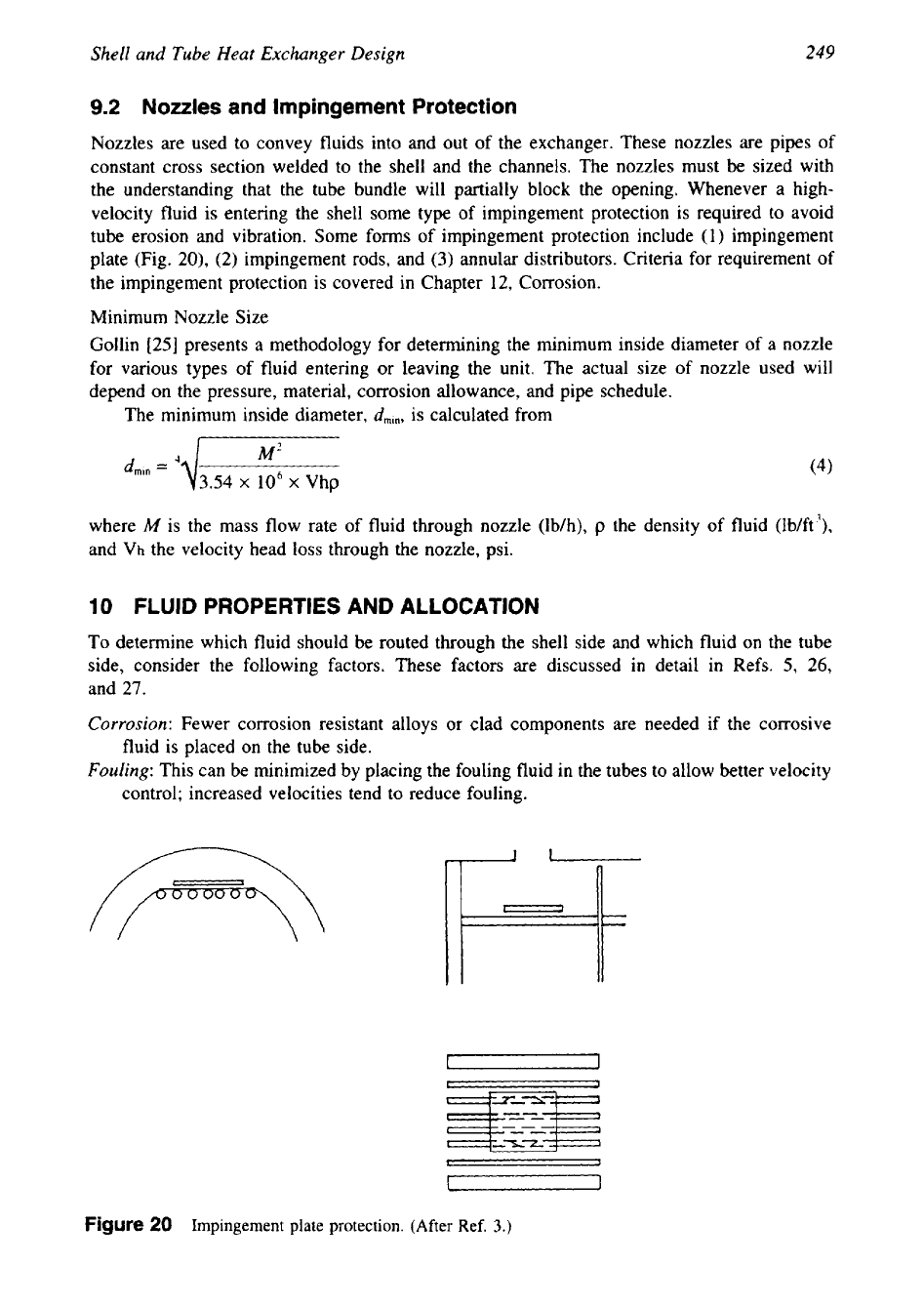
Nozzles
and Impingement Protection
Nozzles are used to convey fluids into and out of the exchanger. These nozzles are pipes of
constant cross section welded to the shell and the channels. The nozzles must be sized with
the understanding that the tube bundle will partially block the opening. Whenever a high-
velocity fluid is entering the shell some type
of
impingement protection is required to avoid
tube erosion and vibration. Some forms of impingement protection include (1) impingement
plate (Fig.
20),
(2)
impingement rods, and
(3)
annular distributors. Criteria for requirement of
the impingement protection is covered in Chapter 12, Corrosion.
Minimum Nozzle Size
Gollin
[25]
presents a methodology for determining the minimum inside diameter of a nozzle
for various types
of
fluid entering or leaving the unit. The actual size of nozzle used will
depend on the pressure, material, corrosion allowance, and pipe schedule.
The minimum inside diameter,
dmi,,
is calculated from
M2
dmm
=
4 4
3.54
x
106
x
Vhp
(4)
where
M
is the mass flow rate of fluid through nozzle (lb/h),
p
the density of fluid (lb/ft3),
and Vh the velocity head loss through the nozzle, psi.
10
FLUID PROPERTIES AND ALLOCATION
To determine which fluid should
be
routed through the shell side and which fluid on the tube
side, consider the following factors. These factors are discussed in detail in Refs.
5,
26,
and
27.
Corrosion:
Fewer corrosion resistant alloys or clad components are needed if the corrosive
fluid is placed on the tube side.
Fouling:
This can be minimized by placing the fouling fluid in the tubes to allow better velocity
control; increased velocities tend to reduce fouling.
Figure
20
Impingement plate protection. (After Ref.
3.)
250
Chapter
5
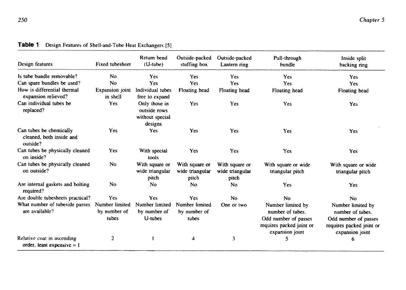
Table
1
Design Features of Shell-and-Tube Heat Exchangers
[5]
~~
~~
~
~~~~
Design features
Fixed tubesheet
Return bend
(U-tube)
Outside-packed
stuffing box
Outside-packed
Lantern ring
Pull-through
bundle
Inside split
backing ring
Is
tube bundle removable?
No
Yes
Yes
Yes Yes
Yes
Can spare bundles be used?
No
Yes
Yes
Yes
Yes
Yes
How is differential thermal
expansion relieved?
Expansion joint
in shell
Individual tubes
free to expand
Floating head Floating head
Floating head
Floating head
Can individual tubes be
Yes
Only those in
Yes
Yes
Yes
Yes
replaced?
outside rows
without special
designs
Can tubes be chemically
Yes
Yes
Yes Yes
Yes
Yes
cleaned,
both
inside and
outside?
Can tubes be physically cleaned
Yes
With special
Yes
Yes
Yes
Yes
on inside?
tools
Can tubes be physically cleaned
No
With square or
With square or
With square or With square or wide
With square or wide
on outside?
wide triangular
wide triangular
wide triangular
triangular pitch
triangular pitch
pitch
pitch
pitch
Are internal gaskets and bolting
No
No
No
No
Yes
Yes
required?
Are double tubesheets practical?
Yes
Yes
Yes
No
No
No
What number of tubeside passes
Number limited
Number limited
Number limited
One or two
Number limited by
Number limited by
are available?
by number of
by number of
by number
of
number of tubes.
number
of
tubes.
tubes
U-tubes
tubes
Odd number
of
passes
Odd number of passes
requires packed joint or
requires packed joint
or
expansion joint
expansion joint
Relative coat in ascending
2
1
4
5
6
order,
least
expensive
=
1

Shell and Tube Heat Exchanger Design
25
I
Cleanability:
The shell side is difficult to clean; chemical cleaning is usually not effective on
the shell side because of bypassing, and requires the cleaner fluid. Straight tubes can be
physically cleaned without removing the tube bundle; chemical cleaning can usually be
done better on the tube side.
Temperature:
For high-temperature services requiring expensive alloy materials, fewer alloy
components are needed when the hot fluid is placed on the tube side.
Pressure:
Placing a high-pressure fluid in the tubes will require fewer costly high-pressure
components and the shell thickness will be less.
Pressure drop:
If the pressure drop of one fluid is critical and must be accurately predicted,
then that fluid should generally be placed on the tube side.
Viscosity:
Higher heat-transfer rates are generally obtained by placing a viscous fluid on the
shell side. The critical Reynolds number for turbulent flow in the shell is about
200;
hence,
when the flow in the tubes is laminar, it may be turbulent if the same fluid is placed on
the shell side. However, if the flow is still laminar when
in
the shell, it is better to place
the viscous fluid only on the tube side since it is somewhat easier to predict both heat
transfer and flow distribution
[27].
Toxic and lethal fluids:
Generally, the toxic fluid should be placed on the tubeside, using a
double tube sheet to minimize the possibility of leakage. Construction code requirements
for lethal service must be followed.
Flow rate:
Placing the fluid with the lower flow rate on the shell side usually results in a more
economical design and a design safe from flow-induced vibration, Turbulence exists on
the shell side at much lower velocities than on the tube side.
11
CLASSIFICATION OF
SHELL
AND TUBE HEAT EXCHANGERS
There are four basic considerations in choosing a mechanical arrangement that provides for
efficient heat transfer between the two fluids while taking care of such practical matters as
preventing leakage from one into the other
[4]:
1.
Consideration for differential thermal expansion of tubes and shell.
2.
Means
of
directing fluid through the tubes.
3.
Means of controlling fluid flow through the shell.
4.
Consideration for ease of maintenance and servicing.
Heat exchangers have been developed with different approaches to these four fundamental
design factors. Three principal types of heat exchangers-(
1)
fixed tube-sheet exchangers,
(2)
U-tube exchangers, and
(3)
floating head exchangers-satisfy these design requirements.
11
.I
Fixed Tube-Sheet Exchangers
This is the most popular type of shell and tube heat exchanger (Fig.
21).
The fixed tube-sheet
heat exchanger uses straight tubes secured at both ends into tube sheets, which are firmly
welded to the shell. Hence, gasketed joints are minimized in this type, and thereby least mainte-
nance is required. Fixed tube-sheet heat exchangers are used where
[28]:
1.
It is desired to minimize the number
of
joints.
2.
Temperature conditions do not represent a problem for thermal stress.
3.
The shell-side fluid
is
clean and tube bundle removal is not required.
Provision is to be made to accommodate the differential thermal expansion of the shell
and the tubes when the thermal expansion is excessive. Fixed tube-sheet exchangers can be
designed with removable channel covers, “bonnet” type channels, integral tube sheets on both
252
Chapter
5
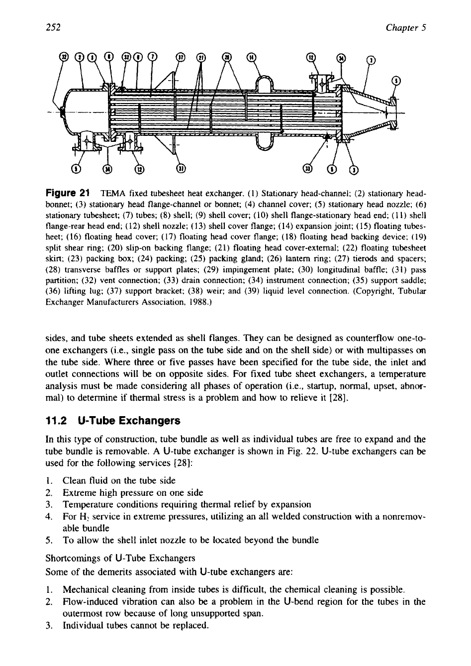
Figure
21
TEMA fixed tubesheet heat exchanger. (1) Stationary head-channel;
(2)
stationary head-
bonnet;
(3)
stationary head flange-channel
or
bonnet;
(4)
channel cover;
(5)
stationary head nozzle;
(6)
stationary tubesheet;
(7)
tubes;
(8)
shell;
(9)
shell cover;
(10)
shell flange-stationary head end;
(1
1) shell
flange-rear head end;
(12)
shell nozzle;
(13)
shell cover flange;
(14)
expansion joint;
(15)
floating tubes-
heet;
(16)
floating head cover;
(
17)
floating head cover flange;
(18)
floating head backing device;
(
19)
split shear ring;
(20)
slip-on backing flange;
(21)
floating head cover-external;
(22)
floating tubesheet
skirt;
(23)
paclung box;
(24)
packing;
(25)
packing gland;
(26)
lantern ring;
(27)
tierods and spacers;
(28)
transverse baffles
or
support plates;
(29)
impingement plate;
(30)
longitudinal baffle;
(3
1) pass
partition;
(32)
vent connection;
(33)
drain connection;
(34)
instrument connection;
(35)
support saddle;
(36)
lifting lug;
(37)
support bracket;
(38)
weir; and
(39)
liquid level connection. (Copyright, Tubular
Exchanger Manufacturers Association,
1988.)
sides, and tube sheets extended as shell flanges. They can be designed as counterflow one-to-
one exchangers (i.e., single pass on the tube side and on the shell side) or with multipasses
on
the tube side. Where three or five passes have been specified for the tube side, the inlet and
outlet connections will be on opposite sides. For fixed tube sheet exchangers, a temperature
analysis must be made considering all phases of operation (i.e., startup, normal, upset, abnor-
mal) to determine if thermal stress is a problem and how to relieve it
[28].
1
I
.2
U-Tube
Exchangers
In this type
of
construction, tube bundle as well as individual tubes are free to expand and the
tube bundle is removable.
A
U-tube exchanger is shown in Fig.
22.
U-tube exchangers can be
used for the following services
[28]:
1.
Clean fluid on the tube side
2.
Extreme high pressure on one side
3.
Temperature conditions requiring thermal relief by expansion
4.
For
H2
service in extreme pressures, utilizing an all welded construction with a nonremov-
able bundle
5.
To allow the shell inlet nozzle to be located beyond the bundle
Shortcomings of U-Tube Exchangers
Some of the demerits associated with U-tube exchangers are:
1.
Mechanical cleaning from inside tubes is difficult, the chemical cleaning is possible.
2.
Flow-induced vibration can also be a problem in the U-bend region for the tubes
in
the
outermost row because
of
long unsupported span.
3.
Individual tubes cannot be replaced.

253
Shell
and
Tube
Heat Exchanger Design
Figure
22
TEMA U-tube heat exchanger. (See Fig.
21
for
key.)
(Copyright, Tubular Exchanger
Manufacturers Association,
1988.)
11.3
Floating Head Exchangers
The floating head exchanger consists of a stationary tube sheet and one floating tube sheet that
is free to accommodate the thermal expansion
of
the tube bundle.
A
floating head exchanger
with TEMA designation
AES
is shown in Fig.
23.
There are four basic types of floating head
exchangers. They are discussed next.
Floating Head, Outside Packed Floating Head
The floating head (P head), outside packed stuffing box heat exchanger uses the outer skirt
of
the floating tube sheet as part of the floating head. The packed stuffing box seals the shell-side
fluid while allowing the floating head to move. The tube bundle is removable. Maintenance is
also very easy since all bolting is from outside only. With this floating head, any leak (from
either the shell side or the tube side) at the gaskets is to the outside and there is no possibility
of contamination of fluids. Since the bundle-to-shell clearance is large (about
1.5
in
or
38
mm), sealing strips are usually required.
Floating Head, Externally Sealed Floating Tube Sheet
The floating head (W head), externally sealed floating tube sheet
or
outside packed lantern
ring heat exchanger uses a lantern ring around the floating tube sheet to seal the two fluids as
Figure
23
TEMA
floating head heat exchanger. (See Fig.
21
for key.) (Copyright, Tubular
Ex
.changer
Manufacturers Association,
1988.)