Kuppan T. Heat Exchanger Design Handbook
Подождите немного. Документ загружается.

2
74
Chapter
5
aspect ratio), which are the items to be determined. Heat-transfer surface
A,,
can be obtained
by various combinations of the parameter
L,,
and
D,,,
for any given tube layout pattern. An
initially assumed aspect ratio of
8
is suggested. Some tube count tables are available
in
Refs.
8,
10,
1
1,
12, and
2
1,
and there is a tube count chart
in
Ref.
46
for various tube layout patterns,
tube diameters, and shell diameters. This helps to calculate
A,,
easily. If such a source is not
available, the designer must assume a rational tube length, and calculate the corresponding
diameter
Dc,,
and finally the shell inside diameter
D,.
Detailed Design Method: Bell-Delaware Method
Designing a shell and tube heat exchanger with the Bell-Delaware method is explained here.
A
flow chart for designing with the Bell-Delaware method is shown
in
Fig.
40.
Evaluation
of
Geometric
Parameters.
After the determination of shell inside diameter and
tube
length, the next step is the evaluation of geometric parameters, such as:
1.
Baffle and bundle geometry
2.
Flow areas
3.
Various flow areas for calculating various correction factors
The calculation of various geometric parameters is known as auxiliary calculations in the
Bell-Delaware method
[4
I].
These calculations are required for the determination of shell-side
heat-transfer coefficient and pressure drop. The auxiliary calculations are defined
in
the follow-
ing steps.
Input
Data.
The Bell-Delaware method assumes that the flow rate and the inlet and the outlet
temperatures (also pressures for a gas or vapor) of the shell-side fluid are specified and that
the density, viscosity, thermal conductivity, and specific heat of the shell-side fluid are known.
The method also assumes that the following minimum set of shell-side geometry data is known
or specified
:
Tube outside diameter,
d
Tube layout pattern,
et,
Shell inside diameter,
D,
Tube
bank outer tube limit diameter,
Doll
Effective tube length (between tubesheets),
L,,
Baffle cut,
B,,
as a percent of
D,
Central baffle spacing,
Lhc.
(also the inlet and outlet baffle spacing,
Lh,
and
Lh,,
if
different from
Lhc)
Number of sealing strips per side,
N,,
From this geometrical information, all remaining geometrical parameters pertaining to the
shell side can
be
calculated or estimated by methods given here, assuming that the standards
of
TEMA
[3]
are met with respect to various shell-side constructional details.
Shell-Side Parameters.
Bundle-To-Shell Clearance,
Lhh.
A suitable tube bundle is selected based
on
the user’s
requirement, and the bundle-to-shell clearance is calculated based upon these equations:
For a fixed tube-sheet heat exchanger,
Lhh
=
12.0
+
O.O05D,
(mm)
For
a U-tube exchanger,
Lh,
=
12.0
+
0.005D,
(mm)
Shell and Tube Heat Exchanger
Design
2
75
I
I
I
I
I
I
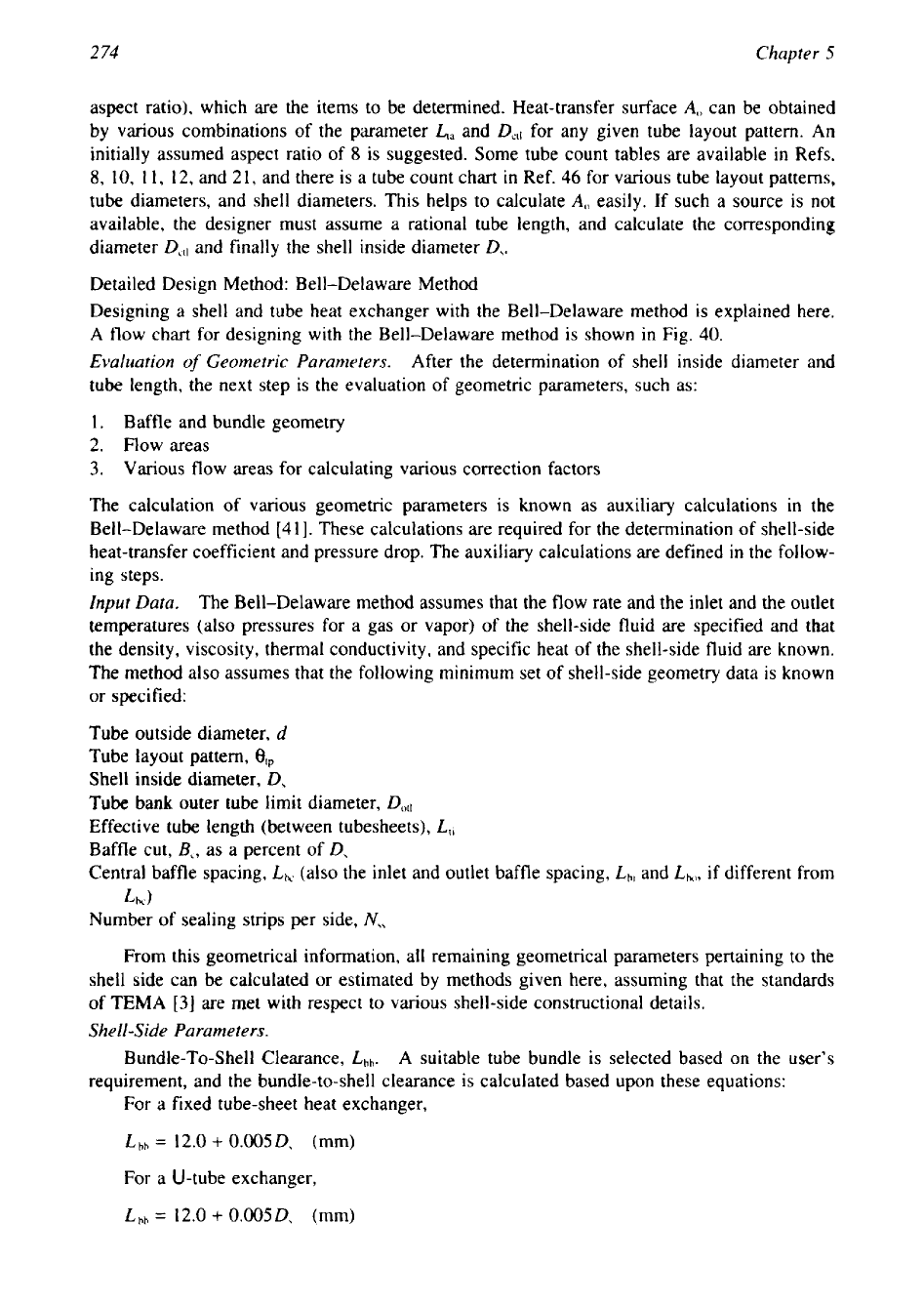
Figure
40
Flow chart for detailed design of
STHE.
(a)
APt
I
allowed pressure drop; (b) compare area
required with area available for heat transfer; and
(c)
I
allowable pressure drop.
Bundle Diameter
(D,,,).
This is computed from the equation
DO,\
=
D,
-
Lhh
=
Dctl
+
d
Shell Length. This is taken as the overall nominal tube length,
L,,,
given by
L,,
=
L,,
+
2L1,
where
L,,
is tube sheet thickness. Its value may be assumed initially as
1
in
(25.4
mm) for
calculation purposes.
276
Chapter
5
Central Baffle Spacing,
LhC.
The number of baffles
Nb
is required for calculation of the
total number of cross passes and window turnarounds. It is expressed as
Nh=--
1
L,l
(14)
Lk
where
L,,
and
Lk
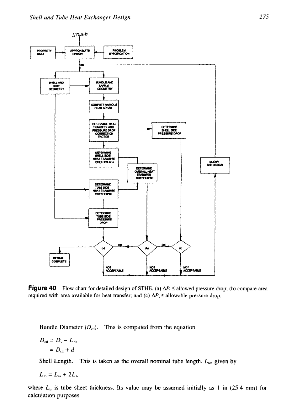
are the tube length and central baffle spacing, respectively. Tube length
L,,
is defined in Fig.
41.
A
uniform baffle spacing
(Lk)
is assumed initially, equal to the shell
diameter,
D,.
To determine
L,,,
we must know the tube sheet thickness. If drawings are not
available, the tube-sheet thickness,
L,,,
can be roughly estimated as
L,,
=
O.lD,
with limit
L,,
=
25
mm. Otherwise assume the minimum
TEMA
tubesheet thickness
[3].
For all bundle types
except U-tubes,
L,,
=
L,,
-
L,,,
whereas for U-tube bundles
L,,
is
nominal tube length.
The number of baffles
is
rounded off to the lower integer value and the exact central
spacing is then calculated by
Auxiliary Calculations, Step-by-step Procedure.
Step
1:
Sequential Baffle Window Calculations.
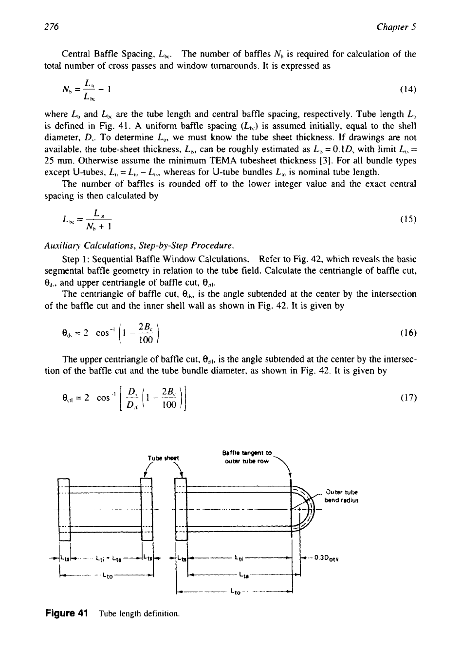
Refer to Fig. 42, which reveals the basic
segmental baffle geometry in relation to the tube field. Calculate the centriangle
of
baffle cut,
&,
and upper centriangle of baffle cut,
OCll.
The centriangle of baffle cut,
ed,,
is the angle subtended at the center by the intersection
of the baffle cut and the inner shell wall as shown in Fig. 42. It is given by
ed,
=
2
(1
-
j
The upper centriangle of baffle cut,
€Icll,
is the angle subtended at the center by the intersec-
tion of the baffle cut and the tube bundle diameter, as shown in Fig. 42. It is given by
Baffle
tangent
to
sheet
outer
tube
row
Lt,--
---,I
Figure
41
Tube
length
definition.
277
Shell and Tube Heat Exchanger Design
b D s 4
(inside shell diameter)
Figure
42
Basic segmental baffle geometry.
Step
2:
Shell-Side Crossflow Area. The shell-side crossflow area,
S,,
is given by
where
Lbb
=
D,
-
Doll
Dctl
=
Doll
-
d
L,p,eff
=
LIP
for
30"
and
90"
layouts
=
o.707Ll,
for
45"
staggered layouts
L,,
=
tube pitch
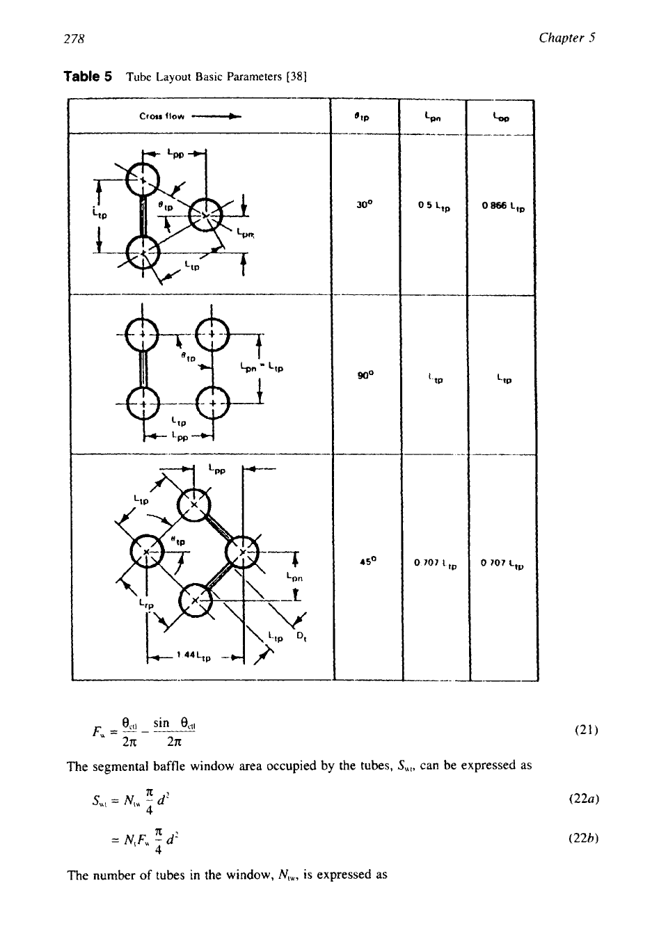
Basic tube layout parameters are given in Table
5.
Step
3:
Baffle Window Flow Areas. The gross window flow area, i.e., without tubes in
the window,
Swg,
is given by
From the calculations of centriangle and gross window flow area, calculate the fraction of
tubes in baffle window,
F,,
and in pure crossflow,
F,,
that is, between the baffle cut
tips
as
indicated in Fig.
42
by distance
D,[1
-
2(Bc/100)]:
where
F,
is the fraction of number of tubes in the baffle window, given by
2
78
Chapter
5
Table
5
Tube
Layout
Basic
Parameters
[38]
I
-I__
Cross
flow
-+
I
The segmental baffle window area occupied by the tubes,
Sul,
can be expressed
as
S,,
=
N,,
-
71
d2
4
The number
of
tubes in the window,
N,,,
is
expressed as

Shell and Tube Heat Exchanger Design
2
79
The net crossflow area through one baffle window,
S,,
is the difference between the gross flow
area,
Swg,
and the area occupied by the tubes,
S,,.
Net crossflow area through one baffle win-
dow,
s,,
is given by
Su
=
s,,
-
s,,
(24)
Step
4:
Equivalent Hydraulic Diameter of a Segmental Baffle Window,
D,.
The equiva-
lent hydraulic diameter of a segmental baffle window,
D,,
is required only for pressure-drop
calculations in laminar flow, i.e., if Re,
<
100.
It is calculated by classical definition of hydrau-
lic diameter, i.e., four times the window crossflow area
S,
divided by the periphery length
in
contact with the flow. This
is
expressed in the following equation:
Step
5:
Number of Effective Tube Rows in Crossflow,
N,,,,
and Baffle Window,
N,,,.
The number of effective tube rows crossed in one crossflow section, i.e., between the baffle
tips, is expressed as
Nrcc:
where
Lpp
is the effective tube row distance in the flow direction, which is given in Table
5.
The effective number of tube rows crossed in the baffle window,
N,,,,
is given by
Step
6:
Bundle-to-Shell Bypass Area Parameters,
sh
and
F,hp.
The bypass area between
the shell and the tube bundle within one baffle,
sb,
is given by
where
L,,
expresses the effect of the tube lane partition bypass width (between tube walls) as
follows:
LpI
is
0
for all standard calculations;
LPI
is half the dimension of the tube lane partition
L,.
For estimation purposes, assume that
Lp
=
d.
For calculations of the correction factors
JI
and
RI,
the ratio of the bypass area,
sh,
to the
overall crossflow area,
S,,
designated as
FFbp,
is calculated from the expression
Step 7: Shell-to-Baffle Leakage Area for One Baffle,
.!&.
The shell-to-baffle leakage
area, is a factor for calculating baffle leakage effect parameters
JI
and
RI.
The diametral
clearance between the shell diameter
D,
and the baffle diameter
Db
is designated as
L,,,
and
given by
The shell-to-baffle leakage area within the circle segment occupied by the baffle is calculat-
ed as:
280
Chapter
5
Step
8:
Tube-to-Baffle-Hole Leakage Area for One Baffle,
Slb.
The tube-to-baffle-hole
leakage area for one baffle,
Slb,
is required for calculation of the correction factors
JI
and
R,.
The total tube-to-baffle leakage area
is
given by
where
Ltb
is diametral clearance between tube outside diameter and baffle hole. TEMA stan-
dards specify recommended clearances as a function of tube diameter and baffle spacing.
Its
value is either
0.8
or
0.4.
Step
9:
Calculate Shell-Side Crossflow Velocity,
U,.
The shell-side crossflow velocity
U,
from shell-side mass flow rate
M,
is given by
where
p,
is the mass density of the shell-side fluid. Equation
33
gives shell-side crossflow
velocity as per the Bell-Delaware method. Since flow-induced vibration guidelines given in
the TEMA Standards
[3]
are based
on
crossflow velocity as per Tinker
[34],
the procedure to
calculate crossflow velocity is given in Appendix
1.
Shell-Side Heat Transfer and Pressure Drop Correction Factors.
Heat Transfer Correction Factors.
In the Bell-Delaware method, the
flow
fraction for
each stream is found by knowing the corresponding flow areas and flow resistances. The heat-
transfer coefficient for ideal crossflow is then modified for the presence of each stream through
correction factors. The shell-side heat-transfer coefficient,
h,,
is given by
where
h,
is the heat transfer coefficient for pure crossflow of an ideal tube bank. The correction
factors in
Eq.
34
are:
J,
is
the correction factor for baffle cut and spacing. This correction factor is used to express
the effects of the baffle window flow
on
the shell-side ideal heat-transfer coefficient
h,,
which is based on crossflow.
J,
is the correction factor for baffle leakage effects, including both shell-to-baffle and tube-to-
baffle leakage.
Jb
is the correction factor for the bundle bypass flow (C and
F
streams).
J,
is
the correction factor for variable baffle spacing in the inlet and outlet sections.
J,
is the correction factor for adverse temperature gradient buildup in laminar flow.
The combined effect of all
of
these correction factors for a reasonably well-designed shell and
tube heat exchanger is typically of the order of
0.6;
i.e., the effective mean shell-side heat-
transfer coefficient for the exchanger is of the order
of
60%
of that calculated if the flow took
place across an ideal tube bank corresponding in geometry to one crossflow section. It is
interesting to note that this value was suggested by McAdams
[47]
in
1933
and has been used
as a rule of thumb
[
11.
Shell and Tube Heat Exchanger Design
281
Pressure Drop Correction Factors. The following three correction factors are applied for
pressure drop:
1. Correction factor for bundle bypass effects,
Rb
2. Correction factor for baffle leakage effects,
RI
3, Correction factor for unequal baffle spacing at inlet and/or outlet,
R,
Step-by-step Procedure
to
Determine Heat Transfer and Pressure Drop Correction Factors.
Step 10: Segmental Baffle Window Correction Factor,
J,.
For the baffle cut range 15-
45%,
J,
is expressed by
J,
=
0.55
+
0.72F,
(35)
This value is equal to 1
.O
for NTIW design, increases to a value as high as 1.15 for small
baffle cut, and decreases to a value of about 0.52 for very large baffle cuts.
A
typical value
for a well-designed heat exchanger with liquid on the shell side is about 1.0.
Step 11: Correction Factors for Baffle Leakage Effects for Heat Transfer,
J,,
and Pressure
Drop,
RI.
The correction factor
JI
penalizes the design if the baffles are put too close together,
leading to an excessive fraction of the flow being in the leakage streams compared to the
crossflow stream.
RI
is the correction factor for baffle leakage effects. For computer applica-
tions, the correction factors are curve-fitted as follows:
J,
=
0.44
(1
-
r,)
+
[l
-
0.44(1
-
rs)]e-2.2rlm
(36)
RI
=
exp[-1.33(1
+
rs)]rlmX
(37)
where
x
=
[-0.15(1
+
rs)
+
0.81
(38)
The correlational parameters used are
where
S,b
is the shell-to-baffle leakage area,
Stb
the tube-to-baffle leakage area, and
S,
the
crossflow area at bundle centerline.
A
well-designed exchanger should have a valve of
J1
not less than
0.6,
preferably in the
range 0.7-0.9. If a low
J1
value is obtained, modify the design with wider baffle spacing,
increase
tube
pitch, or change the tube layout to
90"
or
45".
More drastic measures include
change to double or triple segmental baffles, TEMA
J
shell type, or both.
A
typical value for
RI
is in the range of 0.4-0.5, though lower values may
be
found in exchangers with closely
spaced baffles.
Step 12: Correction Factors for Bundle Bypass Effects for Heat Transfer,
Jb,
and Pressure
Drop,
Rb.
To determine
Jb
and
Rb,
the following parameters must be known:
1.
N,,,
the number
of
sealing strips (pairs) in one baffle
2.
N,,,,
the number of tube rows crossed between baffle tips in one baffle section
The expression for
Jb
is correlated as
282
Chapter
5
where
Chh
=
1.25 for laminar flow, Re,
<_
100,
with the limit of
J,,
=
1,
at
rr,
2
0.5
=
1.35 for turbulent and transition flow, Re,
>
100
The expression for
Rh
is
given
by
where
with the limits of
R,
=
1 at
r\,
2
0.5
chp
=
4.5 for laminar flow, Re,
I
100
=
3.7 for turbulent and transition flow, Re,
>
100
For the relatively small clearance between the shell and the tube bundle,
Jh
is about
0.9:
for
the much larger clearance required by pull through floating head construction, it is about
0.7.
Jh
can be improved using sealing strips.
A
typical value for
Rh
ranges from
0.5
to
0.8,
depending upon the construction type and
number of sealing strips. The lower value would be typical of a pull through floating head
with only one or two pairs of sealing strips, and the higher value typical
of
a fully tubed fixed
tube-sheet exchanger.
Step 13: Heat-Transfer Correction Factor for Adverse Temperature Gradient
in
Laminar
Flow,
J,.
J,
applies only if the shell-side Reynolds number is less than
100
and is fully
effective only
in
deep laminar
flow
characterized by Re, less than
20.
For Re,
<
20,
J,
can be
expressed as:
where
N,
is the total number of tube rows crossed in the entire exchanger.
N,
is given by
For Re, between 20 and 100, a linear proportion is applied resulting in
with the limit
J,
=
0.400 for
Re,
I
100
J,
=
1
for Re,
>
100
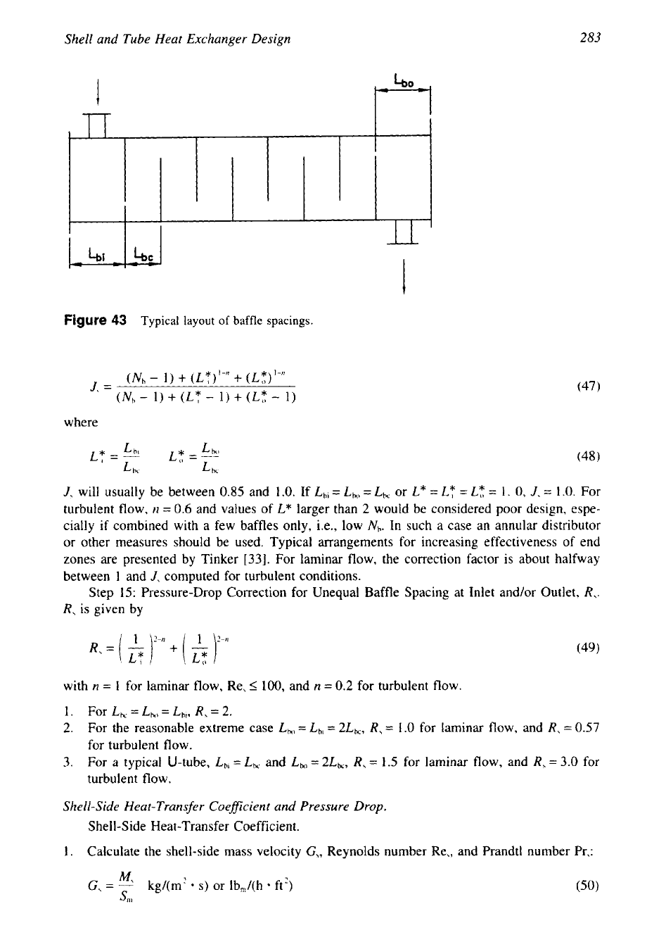
Step 14: Heat-Transfer Correction for Unequal Baffle Spacing at Inlet and/or Outlet,
J,.
Figure 43 shows a schematic sketch of an exchanger where the inlet and outlet baffle spacing
Lb,
and
Lho
are shown in comparison to the central baffle spacing,
Lhc:
283
Shell and Tube Heat Exchanger Design
I
l-r
t
Figure
43
Typical layout
of
baffle
spacings.
where
J,
will usually be between
0.85
and 1
.O.
If Lh)
=
Lho
=
Lbc
or L*
=
LT
=
LR
=
1.
0,
J,
=
1.0. For
turbulent flow,
n
=
0.6
and values of
L*
larger than
2
would be considered poor design, espe-
cially if combined with a few baffles only, i.e., low Nh. In such
a
case an annular distributor
or other measures should be used. Typical arrangements for increasing effectiveness of end
zones are presented by Tinker [33]. For laminar flow, the correction factor is about halfway
between 1 and
J,
computed for turbulent conditions.
Step
15:
Pressure-Drop Correction for Unequal Baffle Spacing at Inlet and/or Outlet,
R,.
R,
is given by
with
n
=
1
for laminar flow, Re,
5
100,
and
n
=
0.2 for turbulent flow.
1. For LhC
=
Lh,)
=
Lbl,
R,
=
2.
2.
For the reasonable extreme case
Lho
=
Lhi= 2Lbc,
R,
=
1.0 for laminar flow, and
R,
=
0.57
for turbulent flow.
3.
For
a
typical U-tube, Lhl=
Lk
and
Lbo
=
2Lk,
R,
=
1.5
for laminar flow, and
R,
=
3.0 for
turbulent flow.
Shell-Side Heat-Transfer Coefficient and Pressure Drop.
Shell-Side Heat-Transfer Coefficient.
1. Calculate the shell-side mass velocity
G,,
Reynolds number Re,, and Prandtl number Pr,:
M,
G,
=
I
kg/(m’
s)
or lb,/(h ft’)
srn