Kuppan T. Heat Exchanger Design Handbook
Подождите немного. Документ загружается.

304
Chapter
6
Tunnel
--a
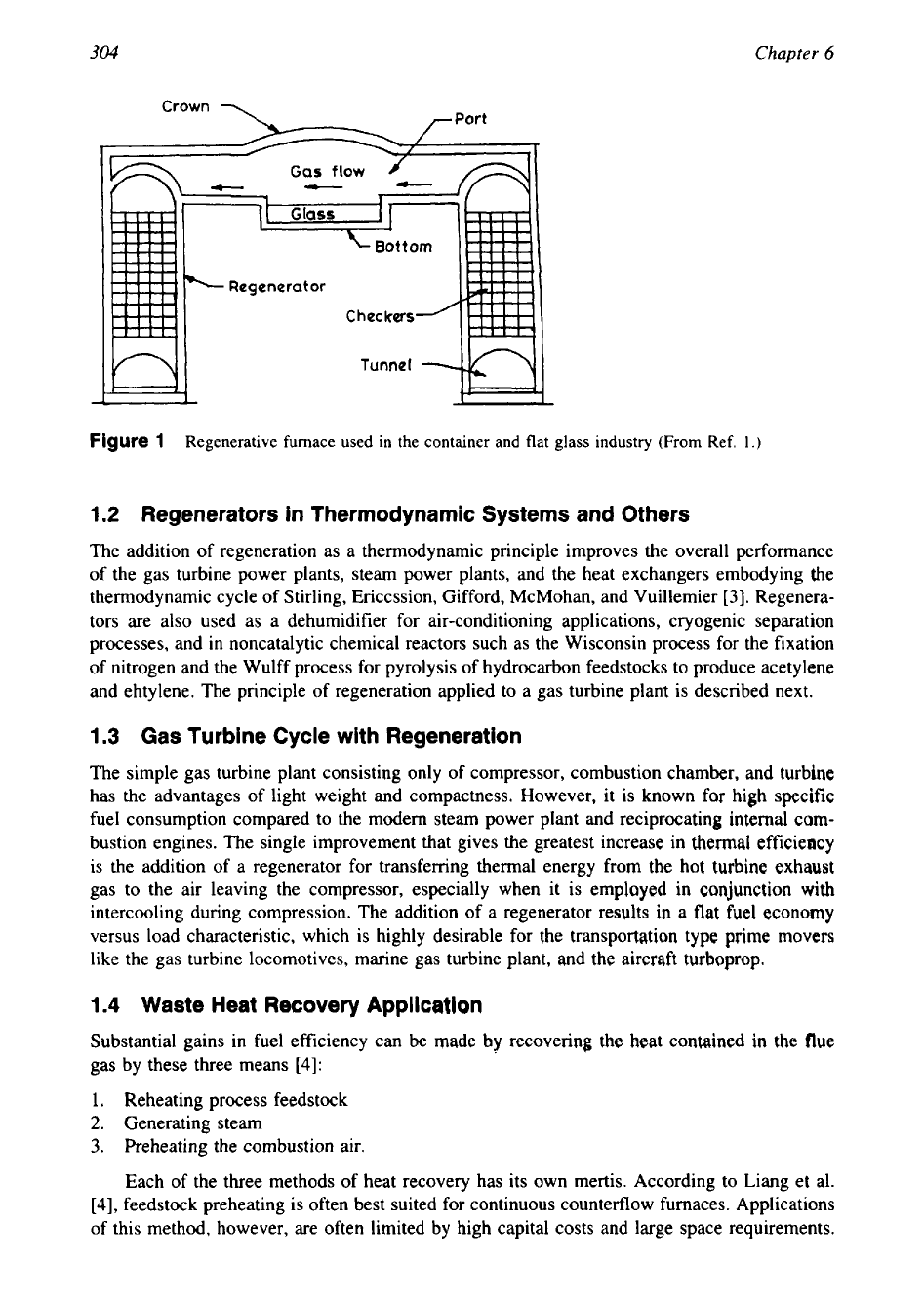
Figure
1
Regenerative furnace used in the container and flat glass industry (From Ref.
1.)
1.2
Regenerators in Thermodynamic Systems and Others
The addition of regeneration as a thermodynamic principle improves the overall performance
of the gas turbine power plants, steam power plants, and the heat exchangers embodying the
thermodynamic cycle
of
Stirling, Ericcssion, Gifford, McMohan, and Vuillemier
[
31. Regenera-
tors are also used as a dehumidifier for air-conditioning applications, cryogenic separation
processes, and in noncatalytic chemical reactors such as the Wisconsin process for the fixation
of nitrogen and the Wulff process for pyrolysis of hydrocarbon feedstocks to produce acetylene
and ehtylene. The principle of regeneration applied to a gas turbine plant is described next.
1.3
Gas
Turbine Cycle with Regeneration
The simple gas turbine plant consisting only of compressor, combustion chamber, and turbine
has the advantages of light weight and compactness. However, it is known for high specific
fuel consumption compared to the modern steam power plant and reciprocating internal com-
bustion engines. The single improvement that gives the greatest increase in
thermal
efficiency
is the addition of a regenerator for transferring thermal energy from the hot turbine exhaust
gas to the air leaving the compressor, especially when it is employed in conjunction with
intercooling during compression. The addition of a regenerator results
in
a flat fuel economy
versus load characteristic, which is highly desirable for the transportation type prime movers
like the gas turbine locomotives, marine gas turbine plant, and
the
aircraft turboprop.
1.4
Waste Heat
Recovery
AppliCath
Substantial gains in fuel efficiency can be made
by
recovering the heat contained in the flue
gas by these three means
[4]:
1. Reheating process feedstock
2.
Generating steam
3.
Preheating the combustion air.
Each of the three methods of heat recovery has its own mertis. According to Liang et
al.
[4],
feedstock preheating is often best suited for continuous counterflow furnaces. Applications
of
this method, however, are often limited by high capital costs and large space requirements.
Reg
en
e
rat0
rs
305
Steam generation is an effective means for heat recovery when the demand for steam corre-
sponds well to the availability of flue gas. Typical methods
of
steam generation include simple
forced recirculation cycle, exhaust heat recovery with economizer, and exhaust heat recovery
with superheater and economizer. Combustion air preheating is the most adaptable of heat
recovery systems because it requires minimum modification
to
the existing system. This im-
proves the system efficiency, and preheating the cold combustion air reduces the fuel require-
ment.
1.5
Fuel
Savings Due to Preheating Combustion
Air
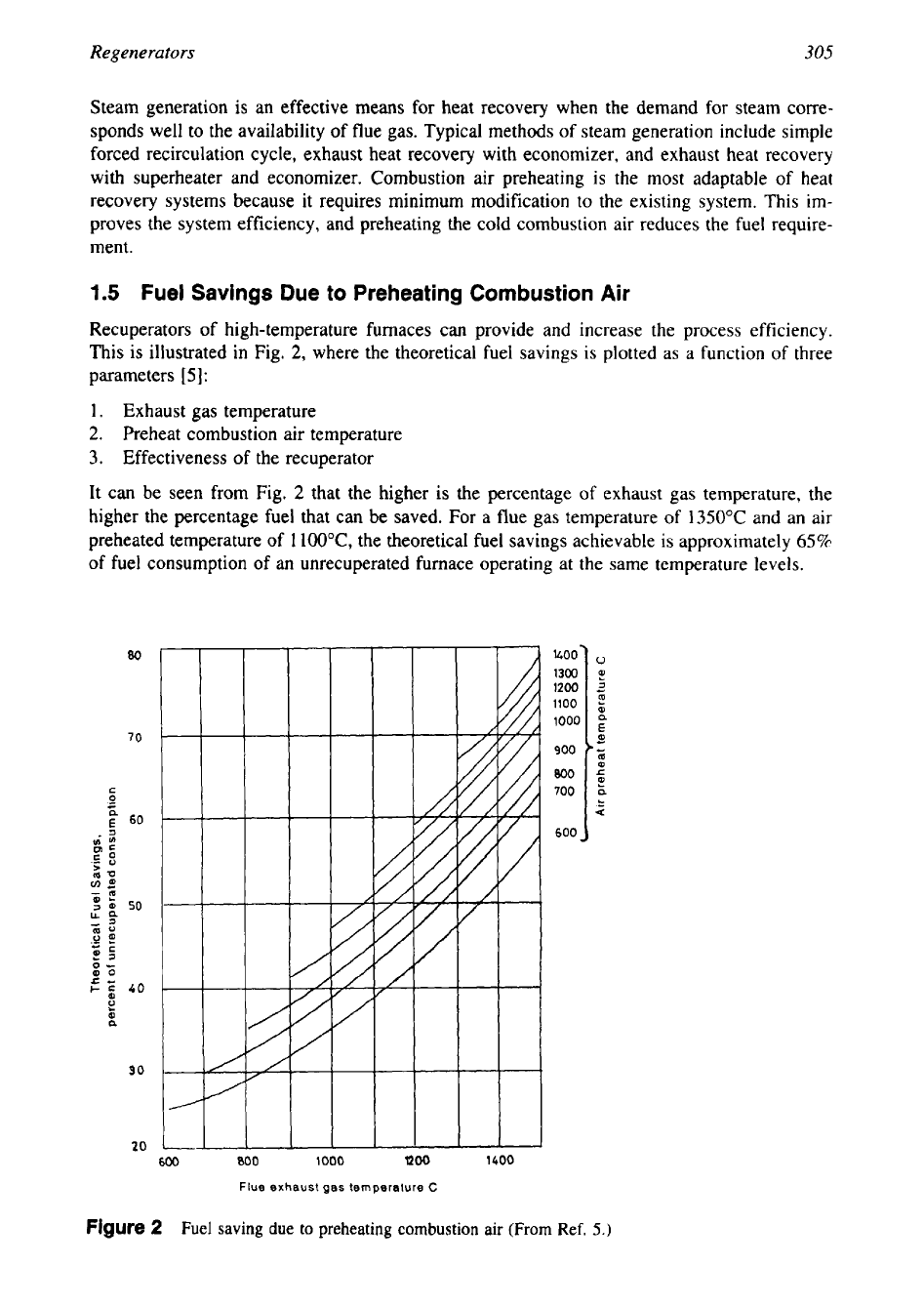
Recuperators
of
high-temperature furnaces can provide and increase the process efficiency.
This is illustrated in Fig.
2,
where the theoretical fuel savings
is
plotted as a function of three
parameters
[
51:
1.
Exhaust gas temperature
2.
Preheat combustion air temperature
3.
Effectiveness of the recuperator
It can be seen from Fig.
2
that the higher is the percentage
of
exhaust gas temperature, the
higher the percentage fuel that can be saved. For a flue gas temperature of
1350°C
and an air
preheated temperature of
1
loO°C,
the theoretical fuel savings achievable is approximately
65%
of fuel consumption of an unrecuperated furnace operating at the same temperature levels.
800
600
600
800
1000
1200
1400
Flue
exhaust
gas
temperature
C
Figure
2
Fuel
saving
due to preheating
combustion
air (From
Ref.
5.)
306
Chapter
6
2
HEATEXCHANGERSUSEDFORREGENERATION
The heat exchanger used to preheat combustion air is called either a recuperator or a regenera-
tor. Thermodynamically the exhaust gas thermal energy is
in
part recuperated
or
regenerated,
and this same thermodynamic function is served regardless of the type of heat exchanger
employed. The thermodynamic principle of regeneration is discussed in the following para-
graphs.
2.1
Recuperator
A
recuperator is a direct transfer type heat exchanger where the two fluids are separated by a
conduction wall through which heat transfer takes place. The fluids flow simultaneously and
remain unmixed. There are no moving parts in the recuperator. Some examples of recuperators
are tubular, plate-fin, and extended surface heat exchangers. Recuperators are used when the
flue gas is clean and uncontaminated.
Merits
of
Recuperators
The recuperators have the advantages of
(1)
ease of manufacture,
(2)
stationary nature,
(3)
uniform temperature distribution and hence less thermal shock, and
(4)
absence of sealing
problem. However, their use is limited due to the requirement of temperature-resistant material
to withstand the high-temperature flue gas and to retain its shape under operating temperature
and pressure. Also, recuperators are subject to degradation
in
heat recovery performance by
fouling from exhaust-gas-borne volatiles and dust.
2.2
Regenerator
A
regenerator consists of a matrix through which the hot stream and cold stream flow periodi-
cally and alternatively. First the hot fluid gives up its heat to the regenerator. Then the cold
fluid flows through the same passage, picking up the stored heat. The passing of hot fluid
stream through a matrix is called the hot blow and the cold flow is called the cold blow. Thus,
by regular reversals, the matrix is alternatively exposed to the hot and cold gas streams, and
the temperature of the packing, and the gas, at each position fluctuates with time. Under steady-
state operating conditions, a number of cycles after the startup of the regenerator, a condition
of cyclic equilibrium is reached where the variations of temperature with time are the same
during successive cycles and the period of hot blow and the cold blow should ensure sufficient
time to absorb and release heat. From this, the regenerators can be distinguished from recupera-
tors. In the case of recuperators, heat is transferred between two fluid streams across some
fixed boundary, and conditions at any point depend, during steady-state operation, only on the
position of that point, whereas in the case of regenerators, the heat transport is transient and
conditions depend both on position and time.
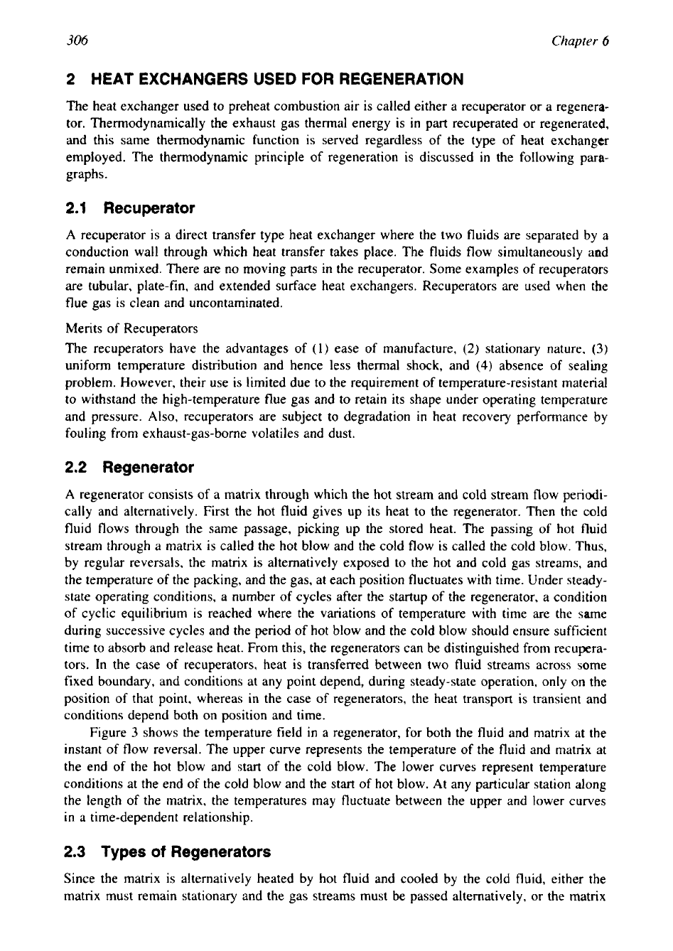
Figure
3
shows the temperature field in a regenerator,
for
both the fluid and matrix at the
instant of flow reversal. The upper curve represents the temperature of the fluid and matrix at
the end of the hot blow and start
of
the cold blow. The lower curves represent temperature
conditions at the end
of
the cold blow and the start of hot blow.
At
any particular station along
the length of the matrix, the temperatures may fluctuate between the upper and lower curves
in
a
time-dependent relationship.
2.3
Types of Regenerators
Since the matrix is alternatively heated by hot fluid and cooled by the cold fluid, either the
matrix must remain stationary and the gas streams must be passed alternatively,
or
the matrix
Regenerators
307
W,
rl
FLOW
LENGTH
O('J
m
Figure
3
Balanced regenerator temperature distribution at switching instants. (a) Hot fluid tempera-
ture at end of the hot blow; (b) matrix temperature at end of the hot blow and start of the cold blow; (c)
matrix temperature at the end
of
the cold blow; and (d) cold fluid temperature at the end
of
cold blow.
(From Ref.
23.)
must be rotated between the passages of the hot and cold gases. Hence the regenerator may be
classified according to its position with respect to time as
(1)
fixed-matrix or fixed-bed and
(2)
rotary regenerators.
2.4
Fixed-Matrix
or
Fixed-Bed Type Regenerator
The fixed-matrix or fixed-bed or storage-type regenerator is a periodic-flow heat-transfer de-
vice with high thermal capacity matrix through which the hot fluid stream and cold fluid stream
pass alternatively.
To
achieve continuous flow, at least two matrices are necessary as shown
in Fig.
1.
The flow through the matrix is controlled by valves. According to the number
of
beds employed, the fixed matrix regenerators are classified into two categories:
(1)
single bed,
and
(2)
dual bed valved. In a dual-bed valved type, shown in Fig.
4,
initially matrix A
is
heated
by the hot fluid and matrix
B
is cooled by the cold fluid. After a certain interval of time, the
valves are operated
so
that the hot fluid flows through
B
and transfers heat to it. Cold fluid,
however, flows through
A
and the fluid is being heated. The switching process continues
periodically. Some examples of storage type heat exchangers are fixed bed air preheaters for
blast furnace stoves, glass furnaces, and open hearth furnaces.
Shape.
The shape of matrix used for the construction of a fixed-matrix regenerator is depen-
dent upon the application. For example, in the glass-making industry, the matrix is often con-
structed from ceramic bricks arranged in patterns such as pigeonhole setting, closed basket
weave setting, and open basket weave setting.
In
the steel-making industry, the gases are much
cleaner and a variety of proprietary configurations such as Andco checkers, McKee checkers,
Kopper checkers, and Mohr checkers are used in place of the brick arrangements. Most
of
these types of checkers employ tongue-and-grove shapes, which provide a bonded structure of
higher stability, because regenerators
in
the steel-making industry are normally much taller
than in the glass industry.
308
Chapter
6
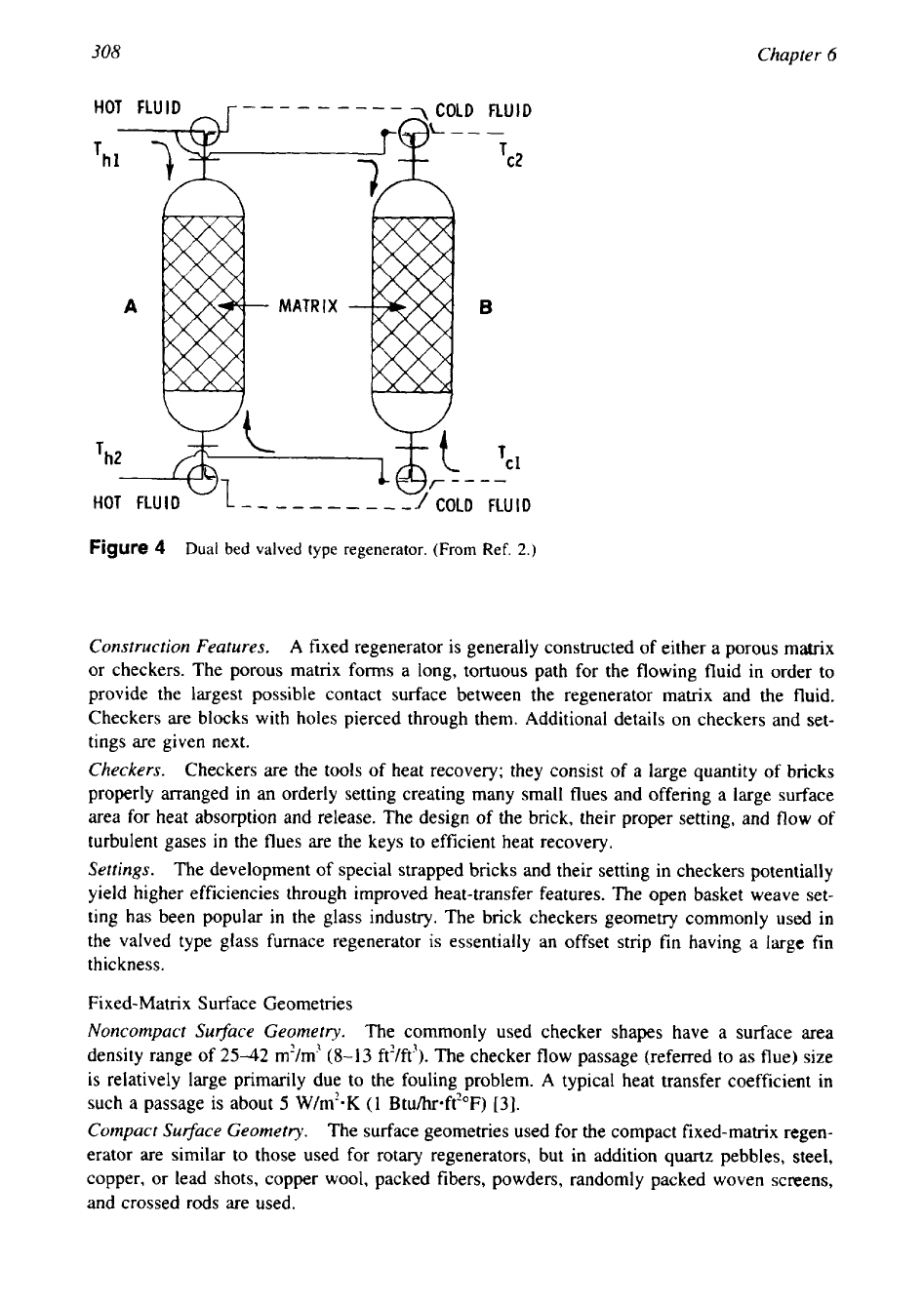
Figure
4
Dual bed valved type regenerator.
(From
Ref.
2.)
Construction
Features.
A
fixed regenerator is generally constructed of either a porous matrix
or checkers. The porous matrix forms a long, tortuous path for the flowing fluid in order to
provide the largest possible contact surface between the regenerator matrix and the fluid.
Checkers are blocks with holes pierced through them. Additional details on checkers and set-
tings are given next.
Checkers.
Checkers are the tools of heat recovery; they consist of a large quantity of bricks
properly arranged in an orderly setting creating many small flues and offering a large surface
area for heat absorption and release. The design of the brick, their proper setting, and
flow
of
turbulent gases
in
the flues are the keys
to
efficient heat recovery.
Settings.
The development of special strapped bricks and their setting in checkers potentially
yield higher efficiencies through improved heat-transfer features. The open basket weave set-
ting has been popular in the glass industry. The brick checkers geometry commonly
used
in
the valved type glass furnace regenerator
is
essentially an offset strip fin having
a
large
fin
thickness.
Fixed-Matrix Surface Geometries
Noncompact Su$ace Geometry.
The commonly used checker shapes have a surface area
density range of
2542
m?m'
(8-13
ft2/ft3). The checker flow passage (referred to as flue) size
is
relatively large primarily due to the fouling problem.
A
typical heat transfer coefficient in
such a passage is about
5
W/m2-K
(1
Btuhr*ft?"F)
[3].
Compact Su$ace Geometry.
The surface geometries used for the compact fixed-matrix regen-
erator are similar to those used for rotary regenerators, but in addition quartz pebbles, steel,
copper, or lead shots, copper wool, packed fibers, powders, randomly packed woven screens,
and crossed rods are used.
Regenerators
309
Size
The fixed-bed regenerators are usually very large heat exchangers, some having spatial dimen-
sions up to
50
m height and having unidirectional flow periods of many hours.
Merits of Fixed-Bed Regenerators
Fixed-bed regenerators consisting of a packed bed of refractory offer the following inherent
advantages
:
1.
If loosely packed, the bed material is free to expand thermally; hence, thermal stresses are
low.
2.
Regenerators of this type are easily equipped
so
that the bed materials can be removed,
cleaned, and replaced.
3.
Unlike a recuperator, accumulated fouling does not reduce the heat exchanger capability
of a regenerator; it merely increases the resistance to flow
[6].
The major disadvantages of fixed-bed regenerators are the additional complexity and cost asso-
ciated with the flow-switching mechanisms.
2.5
Rotary Regenerators
A
rotary regenerator [Fig.
51
consists of a rotating matrix, through which the hot and cold fluid
streams flow continuously. The rotary regenerator is also called a periodic-flow heat exchanger
since each part of the matrix, because of its continuous rotation, is exposed to a regular periodic
flow
of
hot and cold gas streams. The rotary regeneration principle is achieved by two means:
(1) the flow through the matrix is periodically reversed by rotating the matrix, and
(2)
the
matrix is held strationary whereas the headers are rotated continuously. Both the approaches
are rotary because for either design approach, heat-transfer performance, pressure drop, and
leakage considerations are the same, and rotary components must be designed for either system.
The examples for rotary regenerators are
(1)
the Rothemuhle type and
(2)
the Ljungstrom type.
In the Rothemuhle type, the connecting hood rotates while the heat transfer matrix is stationary,
whereas in Ljungstrom type the matrix rotates and connecting hood
is
stationary. The rotary
regenerator
is
used in vehicular gas turbine engines and as a dehumidifier
in
air-conditioning
applications.
Salient Features of Rotary Regenerators
The periodic flow rotary regenerator is characterized by the features like:
1.
A
more compact size
(p
=
8800
m2/m3 for rotating type and 1600 m'/m3 for fixed matrix
type), shape, desired density, porosity, and low hydraulic diameter can be achieved by
pressing the metal strips, wire mesh, or sintered ceramic and hence less expensive surface
per unit transfer area.
2.
The porous matrix provides a long, tortuous path and hence large area of contact for the
flowing fluids.
3.
The absence of a separate flow path like tubes or plate walls but the presence of seals to
separate the gas stream in order to avoid mixing due to pressure differential.
4.
The presence of moving parts, like the rotary core in rotary regenerators and alternate
closing and opening of valves in a fixed regenerator.
5.
With rotary regenerators, high effectiveness can be obtained since the matrix can be
heated up to nearly the full exhaust gas temperature.
6.
To
achieve very high thermal effectiveness approaching unity, the thermal capacity of
31
0
Chapter
6
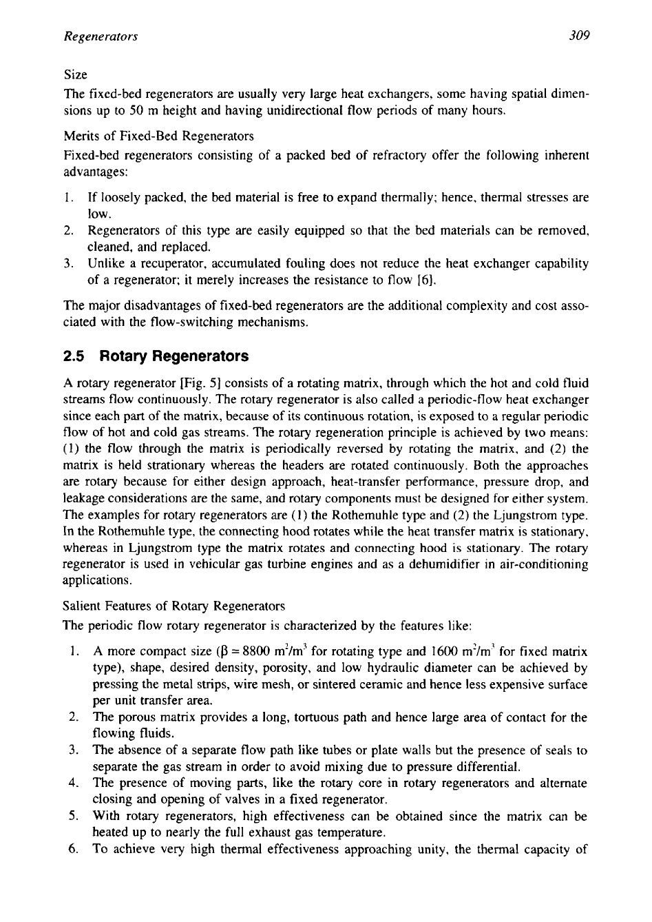
Figure
5
Rotary regenerator. (a)
Disk
and drum type
[20];
(b)
illustrative arrangement
of
matrix
[22];
and
(c)
two alternative
forms of
disc
type rotary regenerator
[30].
the matrix should be very large compared to the working fluids. This requirement restricts
the use of regenerators exclusively to gaseous applications.
7.
Bypass leakage from the high-pressure cold stream to the low-pressure hot stream and
carryover loss from one stream to the other with flow reversal or rotary nature of the
matrix. However, the bypass leakage problem is less in a dehumidifier for an air-condi-
tioning application.
8.
Application to both high temperatures
(800-1100°C)
for metal matrix, and
2000°C
for
Regenerators
31
I
ceramic regenerators for services like gas turbine applications, melting furnaces or steam
power plant heat recovery and cryogenic applications
(-20").
9.
Operating pressure of
5-7
bar for gas turbine applications and low pressure of 1-1.5 bar
for air dehumidifier and waste heat recovery applications.
10.
Regenerators have self-cleaning characteristics because the hot and clod gases flow in
the opposite directions periodically through the same passage. As a result, compact regen-
erators have minimal fouling.
If
heavy fouling is anticipated, regenerators are not used.
11.
Normally a lamina flow condition prevails, due to the small hydaulic diameter.
Rotary Regenerators for Gas Turbine Applications
One of the important areas of rotary regenerator applications
is
in
vehicular gas turbine en-
gines. Starting
in
the 1950s, the vehicle industry intensively researched gas turbine power
plants, which included rotary regenerators. Both disk and drum regenerators were developed
by General Motors and other vehicle builders for gas turbine engines. Their engine programs
significantly advanced all facets of regenerator technology such as improved modeling, heat
transfer surfaces for the matrix, sealing designs, and materials, both metals and ceramics
[2].
Types of Rotary Regenerators
The two most commonly used configurations of rotary regenerators are
(1)
disk and
(2)
drum
types (shown in Fig. 5a and 5b). The disk type matrix consists of alternate layers of corrugated,
flat, thin metal strips wrapped around a central hub or ceramic pressing in a disk shape. Gases
flow normal to the disk. In an ideal circumstance without maldistribution, the single-disk de-
sign is favored due to less seal length and lower seal leakage. Depending upon the applications,
disk-type regenerators are variously referred to as heat wheel, thermal wheel, Munter wheel,
or Ljungstrom wheel. Two alternative forms of disk type rotary regenerator is shown in Fig.
5c. The drum type matrix consists of heat-exchanger material in a hollow drum shape. Gases
flow radially through the drum. The cost of fabricating a drum-type regenerator is much higher
than that for a disk-type regenerator, and hence the drum is not used in any applications.
Drive to Rotary Regenerators
The matrix in the regenerator is rotated by a hub shaft or a peripheral ring gear drive.
Most
ceramic regenerators have been driven at the periphery, probably because of their brittleness.
Operating Temperature and Pressure
The regenerators are designed to cover an operating temperature range from cryogenic to very
high temperatures. Metal regenerators are used for operating temperatures up to about 870°C
(1600°F). Ceramic regenerators are used for higher temperature, up to about
2000°C
(3600°F).
Regenerators are usually designed for a low-pressure application. Rotary regenerators are lim-
ited to operating pressures about 615 kPa or
90
psi and even lower pressures for fixed-matrix
regenerators.
Surface Geometries for Rotary Regenerators
The rotary regenerator surfaces consist of many uninterrupted passages in parallel. The most
common are triangular, rectangular, circular, or hexagonal smooth continuous passages. Details
on the foregoing surface geometries are provided in reference
2.
Interrupted passage surfaces
(such as strip fins, louvre fins) are not used because a transverse flow leakage will be present
if the two fluids are at different pressures. Hence, the matrix generally has continuous, uninter-
rupted flow passages and the fluid is unmixed at any cross section for these surfaces. Some
surface geometries for rotary regenerator are shown in Fig. 6.
312
Chapter
6
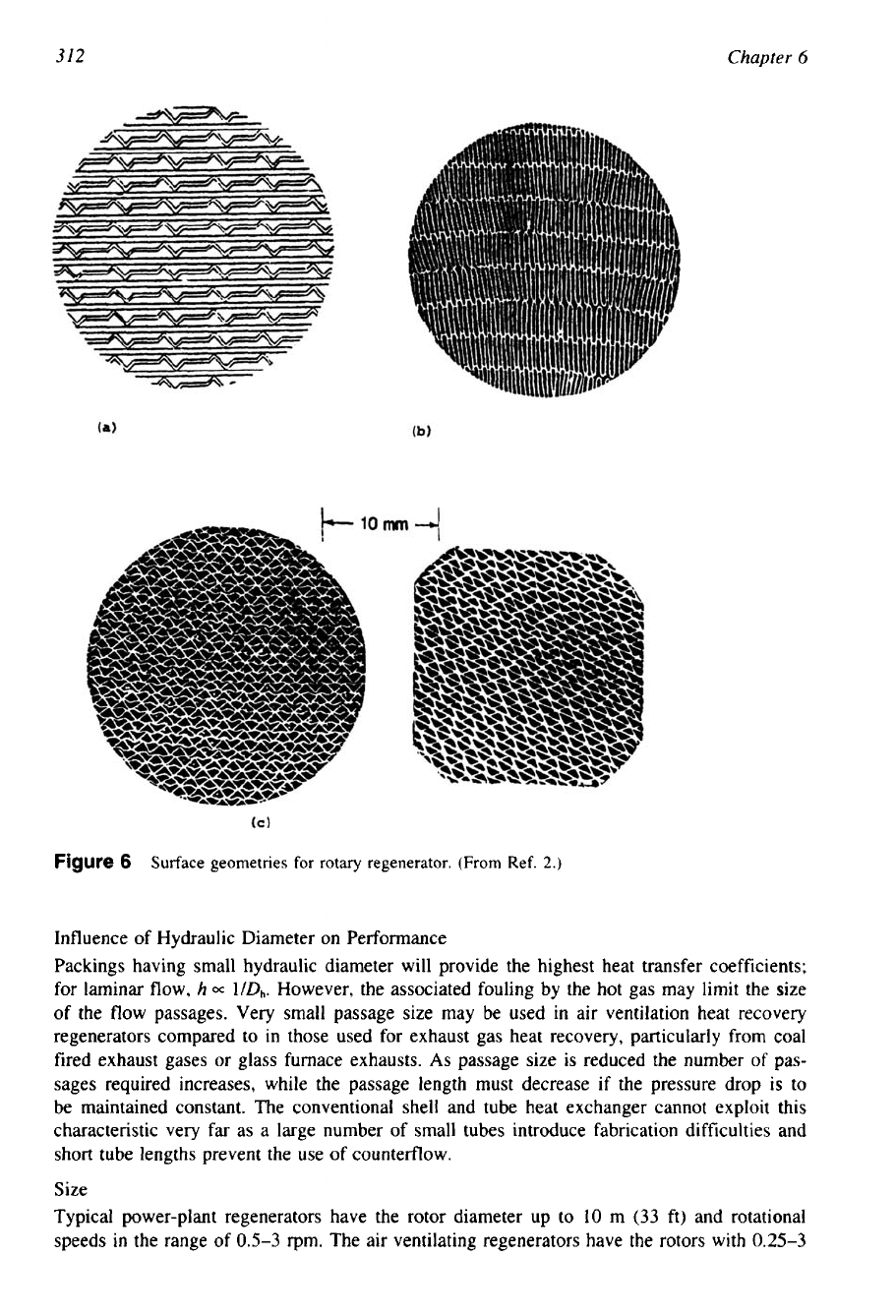
Figure
6
Surface geometries for rotary regenerator. (From Ref.
2.)
Influence of Hydraulic Diameter on Performance
Packings having small hydraulic diameter will provide the highest heat transfer coefficients;
for laminar flow,
h
=
lDh. However, the associated fouling by the hot gas may limit the size
of the flow passages. Very small passage size may be used
in
air ventilation heat recovery
regenerators compared to
in
those used for exhaust gas heat recovery, particularly from coal
fired exhaust gases
or
glass furnace exhausts.
As
passage size is reduced the number
of
pas-
sages required increases, while the passage length must decrease
if
the pressure drop is to
be maintained constant. The conventional shell and tube heat exchanger cannot exploit this
characteristic very far as a large number of small tubes introduce fabrication difficulties and
short tube lengths prevent the use of countedlow.
Size
Typical power-plant regenerators have the rotor diameter up to
10
m
(33
ft) and rotational
speeds
in
the range of
0.5-3
rpm.
The air ventilating regenerators have the rotors with
0.25-3
Regenerators
313
m
(0.8-9.8
ft) diameters and rotational speeds up to
10
rpm. The vehicular regenerators have
diameters up to
0.6
m
(24
in) and rotational speeds up to
18
rpm
[3].
Desirable Characteristics for a Regenerative Matrix
Desirable characteristics of a regenerator matrix include the following
[7]:
1.
A large and solid matrix, for maximum heat capacity.
2.
A porous matrix without obstruction, to minimize the possible blocking and contamination.
3.
A large, finely divided matrix, to achieve maximum heat-transfer rate,
4.
A small, highly porous matrix, for minimum flow losses.
5.
A small, dense matrix, for minimum dead space.
Other desirable matrix properties include negligible thermal conduction in the direction of
fluid flow, to minimize longitudinal conduction, and maximum specific heat, for high thermal
capacity.
Total Heat Regenerators
Up to this point, consideration has only been given to the transfer of sensible heat between
two fluid streams and the intermittant storage of thermal energy, as sensible heat, in a solid
matrix. A number of variations on these conditions are possible; for example, rotary regenera-
tors are designed to transfer both sensible heat and latent heat of vapors mixed with the gas
stream, known as total regenerators. They are intended mainly for air-conditioning applications
and can employ both absorbent fibrous materials and nonabsorbent materials like plastics.
Merits of Regenerators
Among their advantages, regenerators
1.
Can use compact heat transfer materials.
2.
Can use less expensive heat transfer surfaces.
3.
Are self-cleaning because of periodic flow reversals.
4.
Can use simpler header designs.
In contrast, there are several major disadvantages of the periodic flow regenerators. They
are as follows:
Seals suitable for pressure differentials of
4-7
bar represent a major problem; the necessity
of provision
of
seals between the hot fluids due to high pressure differential, and the
leakage problem enhanced due to the thermal expansion and contraction of the matrix.
Many more changes of flow direction are required as compared to the recuperators, result-
ing in flow losses and requiring expensive ducting.
Restrictions in pressure drop make necessary a large flow area with the usual matrix
surface. As a consequence, the advantage of small matrix volume
is
somewhat nullified
by the requirement of bulky approach ducting.
Carryover and leakage losses, especially for the high-pressure compressed air that has
absorbed the compressor work.
Always some amount of mixing of the two fluids due to carryover and bypass leakages.
Where this leakage and subsequent fluid contamination is not permissible (e.g., cryogenic
systems), the regenerator is not used.
The high thermal effectiveness, approaching unity, provided by the regenerator demands
a heat capacity of the matrix considerably larger than that of the working fluid. This
requirement restricts the use of regenerators to gases only.
The rotary designs require a drive and support system.