Kuppan T. Heat Exchanger Design Handbook
Подождите немного. Документ загружается.


334
Chapter
6
-
GLNTU,
-
C"
=
1
(1
+
GLNTU,)
Figure
11
shows GL as a function of the product NTU, for several values of NTU,.
The
curves are for (hA)*
=
1 and
C*
=
0.9
and
1.
The same curves were obtained using (hA)"
=
0.5,
thus indicating that GL is a very weak function of (hA)* [34].
Shah's Solution to Account for the Longitudinal Conduction Effect
For
0.9
5
C*
I
1,
Shah [36] has provided a closed-form formula to take into account the longi-
tudinal conduction effect. However, the following more general method is recommended for
C*
<
1,
by Shah [14].
1.
Use the Razelos method to compute
er,w
for an equivalent balanced regenerator using the
procedure from
Eqs.
51, 52, and 54.
2. Compute
CA
from
Eq.
63
using NTU,, and
h.
3.
Calculate
=
CA~r.hs.
4.
Finally
E
is determined from Eq. 55 or
56
with
E,
replaced by
This procedure yields a value of
E
accurate within
1%
for
1
I
NTU,
I
20 and
Cy
2
1
when
compared to Bahnke and Howard's results.
6.1
0
Fluid Bypass and Carryover on Thermal Effectiveness
Fluid bypass and carryover on thermal effectiveness are discussed in references 14 and 37.
6.1
1
Regenerator Design Methodology
To design a successful regenerator, the engineer must consider many design factors including
the following [2]:
1.
Describe different types
of
regenerative heat exchangers.
2.
Discuss basic heat-transfer process and the correlation
of
cyclic temperature distributions
resulting from storage of thermal energy.
Figure
11
GL
for
longitudinal conduction.
(From Ref.
34.)
Regenerators
335
3.
Relate the regenerator to classical counterflow arrangements to enable trade-offs of heat
transfer, pressure drop, size, and alternative surfaces.
4.
Discuss effects of leakage on both performance and design.
5.
Consider effects of pressure loads, leakage control, and rotation on mechanical design.
6.1
2
Primary Considerations Influencing Design
Primary considerations influencing the design of a regenerator especially for aircraftlvehicular
gas turbine applications may be summarized as follows [38]:
1.
Manufacturing limitations.
2. Cost limitations.
3. Maintenance and cleaning requirements.
4. Mechanical design problems.
5.
Weight, shape, and size limitations.
6.
Limitations on flow friction-power expenditure.
7.
Desired exchanger heat-transfer effectiveness.
6.13 Rating
of
Rotary Regenerators
The basic steps involved in the analysis of a rating problem are the determination of surface
geometrical properties, matrix wall properties, fluid physical properties, Reynolds numbers,
j
(or Nu) and
f
factors corrected for property variations, heat-transfer coefficients,
NTU,,,
C*,
CT,
and pressure drops. The procedure presented for regenerators parallels that for a compact
heat exchanger. Therefore, the rating procedure is not repeated here. However, for details on
a rating procedure from first principles consult Shah
[
141.
6.14 Sizing of Rotary Regenerators
The sizing problem for a rotary regenerator is more difficult. Similar to recuperator design, the
sizing of a regenerator involves decisions on material, surface geometry selection, and mechan-
ical design considerations. Once these are decided, the problem reduces to the determination
of
the disk diameter, division of flow area, disk depth, and disk rotational speed to meet the
specified heat transfer and pressure drops [14]. Sometimes a limitation on the size is also
imposed. One method for a new design would be to assume a regenerator size, consider
it
as
a rating problem, and evaluate the performance as outlined for compact recuperators. Iterate
on
the size until the computed performance matches the specified performance.
A
detailed
sizing procedure is outline in reference 14.
7 MECHANICAL DESIGN
After the heat-transfere surface has been chosen, sizing studies completed, and the regenerator
selected to be compatible with the overall system requirements, the next step involves mechani-
cal design. Mechanical designs must consider items such as [2](1) thermal distortions,
(2)
leakages, (3) pressure loadings, and in the case of the rotary types, (4) a drive system and
(5)
sealing. An important source book on regenerator mechanical design is Mondt
[2].
7.1 Single-Bed and Dual-Bed Fixed Regenerators
Single-bed and dual-bed regenerators can be relatively simple to design. If the bed is composed
of loose pellets, grids or screens are necessary to retain the pellets within a container. The grid

336
Chapter
6
mesh must
be
fine enough to retain the smallest pellet in the bed, yet the mesh must be porous
enough to keep pressure drops low. If the retaining grids are not strong enough at the operating
temperature, the bed will “sag” and loosen the packing.
Leakages.
Both the single-bed and dual-bed valved regenerators have displacement leakage,
that is, displacement of the fluid entrained in the matrix voids at the switching instant.
This
fluid is trapped and “displaced” into the other fluid stream and hence is known as displacement
leakage. In addition to displacement leakage, fixed-bed regenerators may have small primary
leakage of one fluid into the other through leaks in closed switching valves.
7.2
Rotary
Regenerators
The mechanical design
of
a rotary regenerator requires (additionally to the recuperator) the
following items [39]:
1.
A
subdividion of the casing into a rotor and a stator.
2.
Leakage and an effective seal between
the
two gases.
3.
Means for supporting the rotor in the stator.
4. A drive for the rotor.
Items
(2)
and
(4)
are discussed next.
Leakages
Primary leakages in a rotary regenerator can
be
classified as
(1)
labyrinth leakage,
(2)
carryover
or displacement leakage, and
(3)
structural leakage.
Labyrinth
or
Seal Leakage.
This is leakage through the seal stem from the fact that the cold
gases are at much higher pressures than the hot gases. This
is
especially true in the case of gas
turbine with high pressure ratio.
Carryover or Displacement Leakage.
In addition to direct leakage through seals, there is
inevitably a “carryover” or displacement leakage due to air trapped in the matrix as it passes
through the gas side.
Structural Primary Leakage.
Structural leakages take place through any gaps existing
in
the
matrix and the housing.
Any leakage is a serious loss, because it is the air that has absorbed compressor work but
escapes to the atmosphere without passing through the turbine. It is more important than pres-
sure loss, as it affects the net work severely
[40].
Leakage is dependent mainly on pressure
ratio and carryover on matrix rpm. Leakage due to seal leakage and displacement leakage can
amount to
34%
of the airflow out of the compressor
[41].
The effect of
a
given fractional
leakage depends on the values of exchanger effectiveness and cycle pressure ratio.
As
an
example, for a cycle with typical temperatures, component efficiencies, and regenerator effec-
tiveness of 90%, a leakage of
5%
will reduce the net output by about
11
%
while a leakage of
10% will reduce it by twice that amount [40].
Seal Design
In a rotary regenerator, the stationary seal locations control the desired frontal areas for each
fluid and also serve to minimize the primary leakage from the high pressure side to the
low
pressure side. The sealing arrangement must adequately prevent leakage flow, and at the same
time not introduce high frictional resistance for rotation. Because, the matrix is alternately
exposed to hot and cold gases, thermal expansion and contraction add to the sealing problem.
Sealing arrangements will be of two general types
[42]:
(1)
continuous cylindrical seals similar
to a shaft seal, and
(2)
main seals, which divide the high and low pressure sides. The main

Regenerators
337
seals present a more difficult problem because of the effect of the displacement or carryover
lass, the pressure forces under the seal faces, which must be balanced, and allowances to be
made for the thermal distortion of the rotor. Two possible classes of main seal arrangements
are illustrated diagrammatically in Fig. 12. Figure 12a shows the case where the seal bears
directly upon the regenerator matrix. Figure 12b shows the case where the seal bears against a
system of rotor compartments. Certain considerations for seal design are [43]:
1.
The seals must be efficient at very high temperature and pressures but still allow freedom
of movement.
2.
The
seals must accommodate the expansion and contraction accompanying temperature
variations and stll prevent leakage.
Drive for the Rotor
A
design probem encountered with the regenerator is that
of
supporting and driving the matrix
at low speed. The regenerator usually rotates at a speed
of
approximately 20-30 rpm [41]. An
electric drive will be ideal, because of its low rpm and small power requirement.
Thermal Distortion and Transients
A
regenerator is subjected to thermal shock and thermal distortion due to unsteady thermal
conditions. However, this can be minimized by the use of ceramic material. A regenerator
cannot be designed assuming that all operations will be at steady-state conditions. In vehicular
gas turbines system, transients are common. Even industrial regenerators are occasionally ex-
posed to starting and stopping transients. Gentle or long-duration transients are desirable to
minimize thermal distortions and potential thermal stresses [2]. More problems are usually
faced during the warm-up of a regenerator than during stopping because on starting, the matrix
and rotor respond much faster than the surrounding housing. If the housing does not accommo-
date the matrix and the rotor to expand during warm-up, the housing may constrain the matrix
growth and cause thermal stresses.
Pressure Forces
Pressures in the regenerator system exert forces on the matrix or structure. There are two
sources of pressure forces in a rotary regenerator, [2]: One source of pressure forces is due to
pressure difference between the high-pressure cold air and the low-pressure hot gases. This
pressure force depends on the seal arrangement. The seals for a disk can be arranged
so
that
the net force on the support
is
essentially zero. The second source results from pressure drop
of
the fluids flowing through the matrix. This pressure force is the product of the total pressure
drop and the frontal area.
Figure
12
Seals for rotary regenerator. (From Ref.
42.)

338
Chapter
6
a
INDUSTRIAL
REGENERATORS
AND
HEAT
RECOVERY
DEVICES
Apart from recuperators and regenerators, various types of heat recovery devices are available
for many years. Commercially available heat recovery devices for combustion air preheaters
include the following
[44]:
1.
Fluid-bed regenerative heat exchanger.
2.
Fluidized-bed waste heat recovery system.
3.
Vortex-flow direct-contact heat exchanger.
4.
Ceramic bayonet tube heat exchanger or high-temperature burner duct recuperators.
5.
Regenerative burner.
6.
Porcelain-enameled flat-plate heat exchanger.
7.
Radiation recuperators.
8.
Heat-pipe exhangers.
Because of the multitude of different industrial heating processes and exhaust system
designs, there is no one universal type
of
heat-transfer device best suited for all applications.
The following discussion on various types of industrial air preheaters (except heat-pipe ex-
changers) working on the regeneration principle is based on reference
44.
8.1
Fluid-Bed Regenerative Heat Exchangers
In fluid-bed regenerative heat exchangers, fluidized beds of pellets recover heat from hot
ex-
haust gas and transfer this heat to cold combustion air
[45].
The basic fluid-bed heat exchanger
consists of an insulated cylindrical tower incorporating an upper and a lower chamber as shown
Figure
13.
Each chamber is fitted with several horizontal perforated trays. Hot exhaust gases
/-\
To
stack recycle
pellet
heat
in0
-
gases
Preheated
process
air
I
I
Pellet recycling
system
Figure
13
Fluid bed regenerator. (From Ref.
45.)

Regenerators
339
enter the upper chamber near its base and rise to the outlet near the top, heating counterflowing
alumina pellets as they fall. The heated pellets pass through an aperture into the lower chamber,
where they give up their heat to the cold air. Air enters the lower chamber near the base and
exits near the top. Direct contact of gas and air streams with the heat exchange media, namely,
the alumina pellets, coupled with controlled dwell time at the trays, results in high heat-transfer
rates. By controlling the rate of pellet recycling, the temperature of the air being heated can
be held constant within wide variations of gas inlet temperature and volume. As a part of this
heat exchange system, an auxiliary pneumatic system is incorporated for recycling alumina
pellets.
8.2
Fluidized-Bed Waste Heat Recovery
Fluidized-bed waste heat recovery (FBWHR) systems are being developed to preheat combus-
tion air for industrial furnaces. FBWHR systems employ a heat-transfer particulate media,
which is heated as
it
falls through the upward-flowing flue gases in a raining bed heat ex-
changer [9,46]. This type of heat exchanger is known as a fluidized-bed heat exchanger. Fluid-
ized-bed heat exchangers (FBHE) offer the potential for economic recovery of high-tempera-
ture (2000-3000°F) heat from the flue gases
of
industrial processes such as steel soaking pits,
aluminum remelt furnaces, and glass melting furnaces.
A fluidized-bed heat exchanger (Fig. 14) consists
of
horizontal finned heat exchanger
tubes with a shallow bed of fine inert particles, which move upward with gas flow and give
up the heat to the finned tubes, which in turn transfer heat to cold air passing through them.
A
thin steel plate with small perforations supports the bed and distributes the hot gas evenly.
The perforations are uniform with a hole size of 1.5 mm diameter or less, and the holes are
spaced to provide a free flow area of 3-10%. For many applications only ceramic distributor
plates will withstand the temperatures and corrosive environments of flue gases. Among the
FBHE advantages are enduring the hostile environments such as elevated temperature, fouling
particulates, corrosive gases, corrosive particulates, and thermal cycling
[9].
Most surfaces are
kept clean by fluidizing action.
STEAM OUTLET
FINNED
MEAT
EXCHANGE TUBE BUNDLE
IS
PUT
D
F
NA
PERFORATED STEEL SHEET
BRUSH
AUTOMATICALLY
CLEANS PUT€
UNOERNEATH
UPWARD
GAS FLOW
GIVES
UP
HEAT
IN
FLUID BED
Figure
14
Fluidized bed regenerator. (From
Ref.
19.)

340
Chapter
6
8.3
Vortex-Flow Direct-Contact Heat Exchangers
The vortex-flow direct-contact heat exchanger represents a new approach for high-temperature
(2500°F)
heat recovery from industrial waste heat flue gas with a simple payback period. In
the vortex-flow direct-contact heat exchanger, the heat conduction material wall of conven-
tional metal or high-temperature ceramic material is replaced by a vortex-induced fluid dy-
namic gas boundary, which separates the tangentially rotating hot and cold gas flows between
which heat exchange is desired
[47].
The
VFHE
shown in Fig.
15
is a cylindrical cavity into which separate hot flue gas and
cold preheat air gas flows are injected. Injection of the gases
is
such that a vortex-flow pattern
is established in the cavity, providing confinement
of
hot fluid to the central region
of
the
cavity surrounded by cold air stream. Solid particles of size
20-200
pm diameters as a medium
to exchange heat between hot and cold streams are injected into the hot spiraling gas stream.
Due to centrifugal action these particles pass into the surrounding cold gas rotating flow, to
which the particles transfer heat. Figure
16
shows the particles’ trajectory projections. Upon
reaching the outside cavity surface, the particles are entrained in the outermost region of the
vortex flow and removed with a portionof the cold flow, which exits at the periphery (exhaust
end wall) as shown in Fig.
16.
The
VFHE
requires a particle injection and separation subsystem
to collect and recycle the particle to the vortex chamber for continued heating and cooling
cycles.
8.4 Ceramic Bayonet Tube Heat Exchangers
Babcock and Wilcox
(B&W)
and the Department of Energy (DOE) developed high-tempera-
ture burner duct recuperator
(HTBDR)
systems capable of recovering waste heat from high-
temperature flue gas using ceramic bayonet elements
[48,49].
The high-temperature burner
duct recuperators consist of silicon carbide ceramic bayonet tubes suspended into the exhaust
FLUE
EXHAUST
STAGNATION
A
FLOW
DIAGRAM
FLUEIPARTICLE
*
INJECTION
Figure
15
Vortex
flow
direct contact regenerator.
(From
Ref.
47.)
-
--
Regenerators
341
Figure
16
Particles trajectory projections in a
vortex flow
direct contact regenerator. (From Ref.
47.)
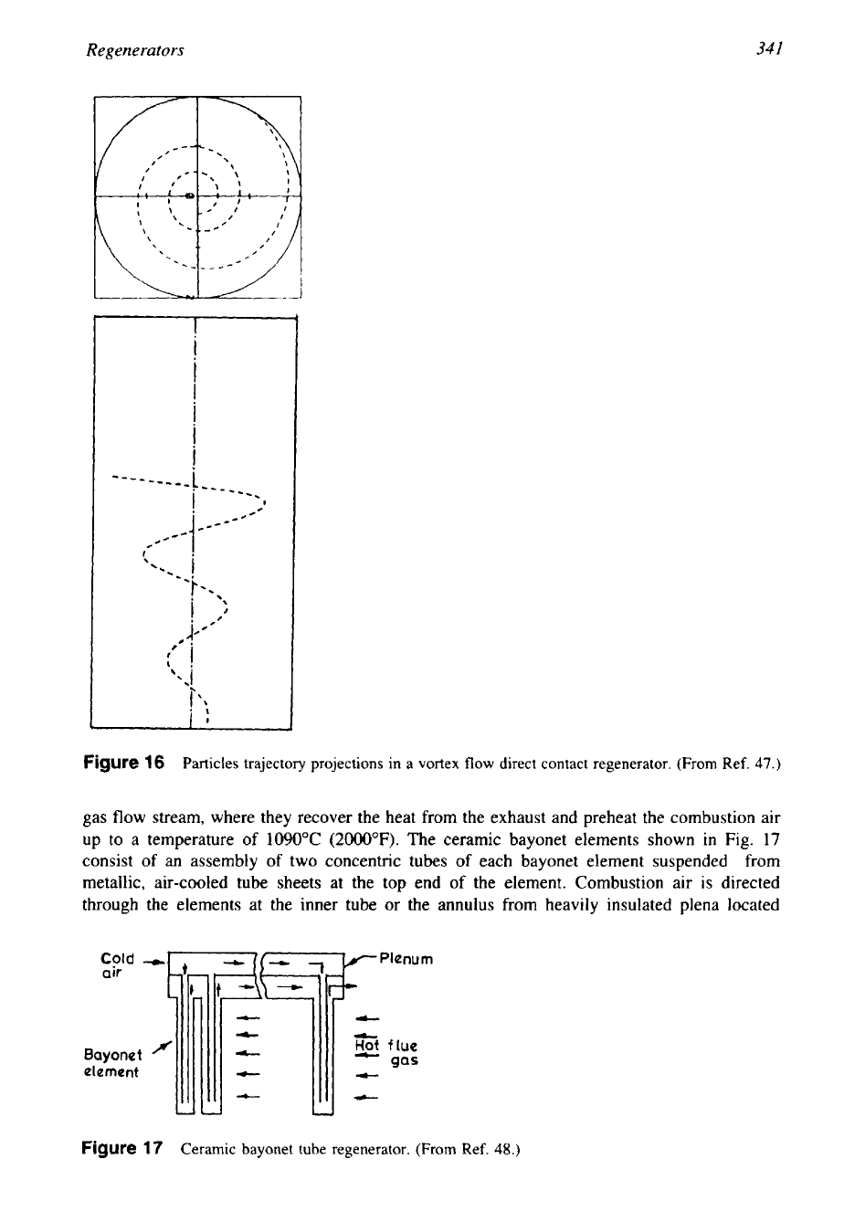
gas flow stream, where they recover the heat from the exhaust and preheat the combustion air
up to
a
temperature of
1090°C
(2000'F).
The ceramic bayonet elements shown in Fig.
17
consist of
an
assembly of two concentric tubes of each bayonet element suspended from
metallic, air-cooled tube sheets at the top end of the element. Combustion air is directed
through the elements at the inner tube or the annulus from heavily insulated plena located
Cold
air
Bayonet
element
Figure
17
Ceramic bayonet tube regenerator. (From Ref.
48.)

342
Chapter
6
MODE
-
2
MODE-
1
Ex
haus
t
gas
Combustion
air
Exhaust
gas
Combustion
air
Figure
18
Regenerative
burner.
(From
Ref.
7.)
above the tube sheets. The tubes of each element are free to expand or contract under the
influence of temperature variations. The ceramic bayonet elements are also expected to ease
maintenance and to best deal with problems associated with thermal stress, leakage, and stress-
related corrosion.
8.5
Regenerative Burners
The reGen regenerative burner, an all-ceramic high-temperature burner, close coupled to a
compact, fast-cycle, ceramic regenerator, provides air preheats in excess of
85%
of the process
temperature in fuel-fired applications up to
1399°C
(2550°F)
[7].
Figure 18 shows one
corn-
plete regenerative unit comprised of two burners, two regenerators, a reversing valve, and the
related pipings. While one of the burners fires, drawing the preheated air fed through its regen-
erator, exhaust gas is drawn through the other burner and down into its associated regenerator,
then discharged to the atmosphere. After a sufficient interval the reversing operation takes
place.
8.6
Porcelain-Enameled Flat-Plate Heat Exchangers
Porcelain-enameled heat exchangers offer cost-effective solutions to problems of heat recovery
from extremely corrosive gases that preclude the use of carbon steel or common types of
stainless steels
[50].
Porcelain enamel is a glass coating material that is applied to a metal
substrate to protect the base metal. The base metal gives strength and rigidity; the metal can
be steel, cast iron, aluminum, or copper, but mostly steel
is
used on a larger scale. The glass
coating offers significant corrosion resistance to the corrosive flue gas. The porcelain-enameled
coating finds application in flat-plate heat exchangers of the open channel air preheater
(OCAP)
type for advanced heat recovery. The
OCAP
is a plate-type exchanger characterized by a
nonweld construction of the heat transfer core. The enameled plates are assembled into a
floating construction. Elastic springs are used between all adjacent plates to ensure a uniform
distribution of the dead weights and to allow for the thermal expansion and contraction
in
operation. This floating core is enclosed in a rigid frame, again without any welding or any
damage to the porcelain enamel layer.

Regenerators
343
8.7
Radiation Recuperators
Metallic recuperator for industrial furnaces are generally of the following types
[5
11:
1.
Convective units, operating at flue gas temperatures up to a maximum of
1
100°C
(2000°F).
2.
Radiation-type units, that is, the heat-transfer mode
is
by radiation, operating at tempera-
ture ranges of nearly
900°C
to
1500°C (2700°F).
In radiation-type recuperators, parallel
flow is essential to control the operating temperatures of the heating surface.
A
combina-
tion of parallel flow and counterflow is required to reach the highest recuperator efficien-
cies
of
air temperature
of
above
800°C
(1500°F).
Typical radiation recuperators include a
double-shell parallel-flow radiation recuperator consisting
of
two concentric cylinders-
through the inner shell the flue gas
flows
and through the annulus the cold air flows in a
parallel direction-as well as cage-type radiation recuperators for very large high-tempera-
ture furnaces, with a combination
of
parallel flow
and
counterflow units.
I
--
Vessel
wall
‘/-tf
t
Hear
in
6
Liquid
return
~n
wtck
,
,\-
Finned
heat
piws
Figure
19
Heat pipe heat exchanger.
(From
Ref.
52.)