Kuppan T. Heat Exchanger Design Handbook
Подождите немного. Документ загружается.

264
Chapter
5
Baffle
/
Tube
0000 0000
000
000
c
Byposs
stream
F
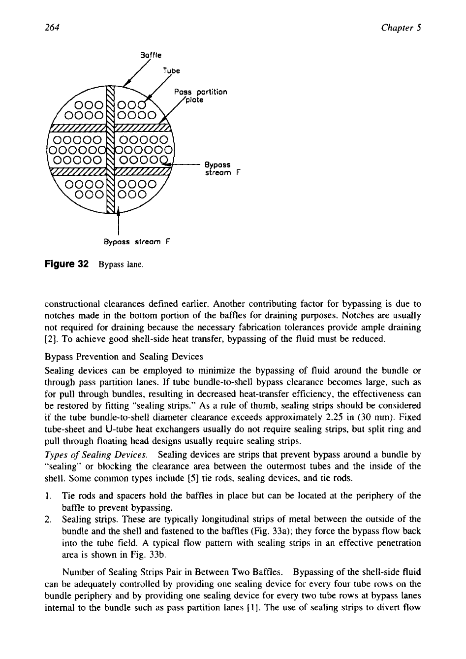
Figure
32
Bypass
lane.
constructional clearances defined earlier. Another contributing factor for bypassing is due to
notches made in the bottom portion of the baffles for draining purposes. Notches are usually
not required for draining because the necessary fabrication tolerances provide ample draining
[2].
To achieve good shell-side heat transfer, bypassing of the fluid must be reduced.
Bypass Prevention and Sealing Devices
Sealing devices can be employed to minimize the bypassing of fluid around the bundle or
through pass partition lanes. If tube bundle-to-shell bypass clearance becomes large, such as
for pull through bundles, resulting in decreased heat-transfer efficiency, the effectiveness can
be restored by fitting “sealing strips.”
As
a rule of thumb, sealing strips should be considered
if the tube bundle-to-shell diameter clearance exceeds approximately
2.25
in (30 mm). Fixed
tube-sheet and U-tube heat exchangers usually do not require sealing strips, but split ring and
pull through floating head designs usually require sealing strips.
Types
of
Sealing
Devices.
Sealing devices are strips that prevent bypass around a bundle by
“sealing” or blocking the clearance area between the outermost tubes and the inside
of
the
shell. Some common types include
[5]
tie rods, sealing devices, and tie rods.
1.
Tie rods and spacers hold the baffles in place but can be located at the periphery
of
the
baffle to prevent bypassing.
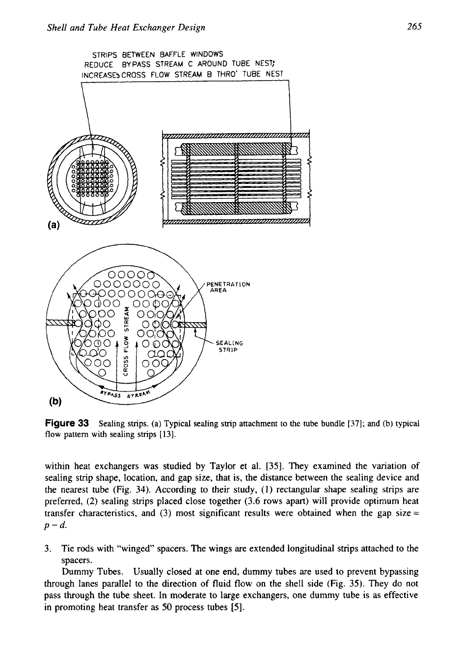
2.
Sealing strips. These are typically longitudinal strips
of
metal between the outside of the
bundle and the shell and fastened to the baffles (Fig. 33a); they force the bypass flow back
into the tube field. A typical flow pattern with sealing strips in an effective penetration
area is shown in Fig. 33b.
Number of Sealing Strips Pair in Between Two Baffles. Bypassing of the shell-side fluid
can be adequately controlled by providing one sealing device for every four tube rows on the
bundle periphery and by providing one sealing device for every two tube rows at bypass lanes
internal to the bundle such as pass partition lanes
[I].
The use of sealing strips to divert flow
265
Shell and
Tube
Heat Exchanger Design
STRIPS BETWEEN BAFFLE WINDOWS
REDUCE BYPASS STREAM C AROUND TUBE NEST;
INCREASESCROSS FLOW STREAM
B
THRO’ TUBE NEST
I
PEN€
T
RAT
I
ON
Figure
33
Sealing
strips.
(a) Typical sealing strip attachment to
the
tube bundle
[37];
and (b) typical
flow
pattern
with
sealing strips
[13].
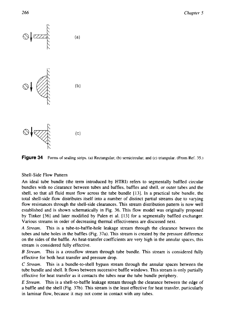
within heat exchangers was studied by Taylor et al.
[35].
They examined the variation of
sealing strip shape, location, and gap size, that is, the distance between the sealing device and
the nearest tube (Fig.
34).
According to their study,
(1)
rectangular shape sealing strips are
preferred,
(2)
sealing strips placed close together
(3.6
rows apart) will provide optimum heat
transfer characteristics, and
(3)
most significant results were obtained when the gap size
=
p
-
d.
3.
Tie rods with “winged” spacers. The wings are extended longitudinal strips attached to the
spacers.
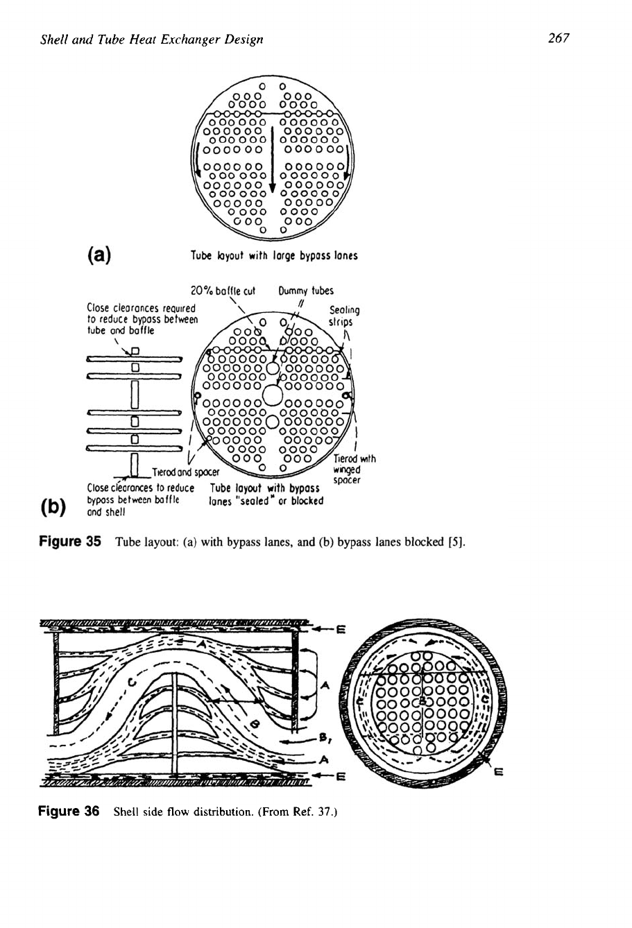
Dummy Tubes.
Usually closed at one end, dummy tubes are used to prevent bypassing
through lanes parallel to the direction of fluid flow on the shell side (Fig.
35).
They
do
not
pass through the tube sheet. In moderate to large exchangers, one dummy tube is as effective
in promoting heat transfer as
50
process tubes
[5].
266
Chapter
5
Figure
34
Forms
of
sealing
strips.
(a)
Rectangular;
(b)
semicircular;
and
(c) triangular.
(From
Ref.
35.)
Shell-Side Flow Pattern
An ideal tube bundle (the term introduced by HTRI) refers to segmentally baffled circular
bundles with no clearance between tubes and baffles, baffles and shell, or outer tubes and the
shell,
so
that all fluid must flow across the tube bundle [13]. In a practical tube bundle, the
total shell-side flow distributes itself into a number
of
distinct partial streams due to varying
flow resistances through the shell-side clearances. This stream distribution pattern is now well
established and is shown schematically in Fig. 36. This flow model was originally proposed
by Tinker
[36]
and later modified by Palen et al. [13] for a segmentally baffled exchanger.
Various streams in order of decreasing thermal effectiveness are discussed next.
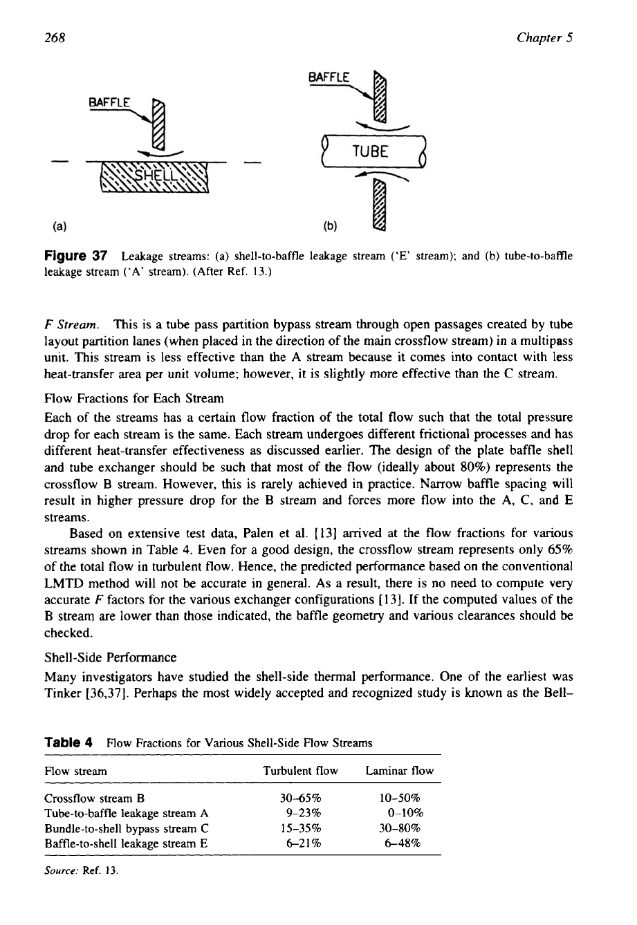
A
Stream.
This is a tube-to-baffle-hole leakage stream through the clearance between the
tubes and tube holes in the baffles (Fig. 37a). This stream is created by the pressure difference
on the sides of the baffle.
As
heat-transfer coefficients are very high
in
the annular spaces, this
stream is considered fully effective.
B
Stream.
This is a crossflow stream through tube bundle. This stream is considered fully
effective for both heat transfer and pressure drop.
C
Stream.
This is a bundle-to-shell bypass stream through the annular spaces between the
tube bundle and shell. It flows between successive baffle windows. This stream is only partially
effective for heat transfer as it contacts the tubes near the tube bundle periphery.
E
Stream.
This is a shell-to-baffle leakage stream through the clearance between the edge of
a baffle and the shell (Fig. 37b). This stream
is
the least effective for heat transfer, particularly
in
laminar flow, because
it
may not come
in
contact with any tubes.
267
Shell and
Tube
Heat Exchanger Design
Figure
36
Shell side
flow
distribution.
(From
Ref.
37.)
268
Chapter
5
Figure
37
Leakage streams: (a) shell-to-baffle leakage stream
(‘E’
stream); and (b) tube-to-baffle
leakage stream
(‘A’
stream). (After Ref. 13.)
F
Stream.
This
is a tube pass partition bypass stream through open passages created
by
tube
layout partition lanes (when placed in the direction of the main crossflow stream)
in
a multipass
unit. This stream is less effective than the
A
stream because it comes into contact with
less
heat-transfer area per unit volume; however, it is slightly more effective than the
C
stream.
Flow Fractions for Each Stream
Each of the streams has a certain flow fraction of the total flow such that the total pressure
drop for each stream is the same. Each stream undergoes different frictional processes and has
different heat-transfer effectiveness as discussed earlier. The design of the plate baffle shell
and tube exchanger should be such that most of the flow (ideally about
80%)
represents the
crossflow
B
stream. However, this is rarely achieved in practice. Narrow baffle spacing will
result
in
higher pressure drop for the
B
stream and forces more flow into the
A,
C,
and
E
streams.
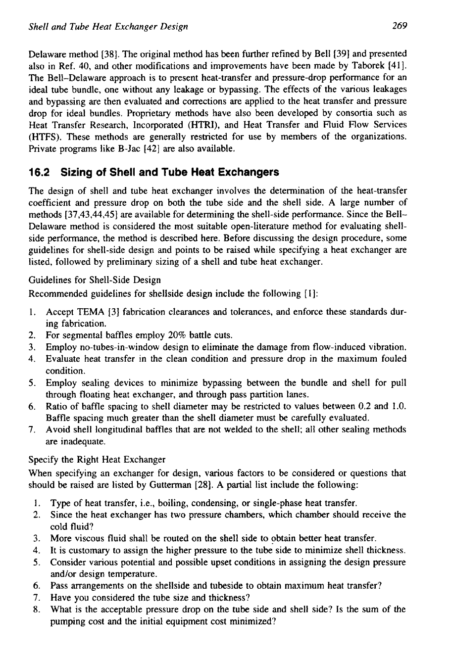
Based on extensive test data, Palen et al.
[13]
arrived at the flow fractions for various
streams shown
in
Table
4.
Even for a
good
design, the crossflow stream represents only
65%
of the total flow
in
turbulent flow. Hence, the predicted performance based on the conventional
LMTD
method will not
be
accurate in general.
As
a result, there is no need to compute very
accurate
F
factors for the various exchanger configurations
[
131.
If the computed values of the
B
stream are lower than those indicated, the baffle geometry and various clearances should be
checked.
Shell-Side Performance
Many investigators have studied the shell-side thermal performance. One of the earliest was
Tinker
[36,37].
Perhaps the most widely accepted and recognized study
is
known as the Bell-
Table
4
Flow Fractions for
Various
Shell-Side Flow Streams
Flow stream Turbulent flow Laminar flow
~
~
~ ~ ~ ~
Crossflow stream
B
3045%
10-50%
Tube-to-baffle leakage stream
A
9-23%
0-10%
Bundle-to-shell bypass stream
C
15-35% 30-80%
Baffle-to-shell leakage stream
E
621%
648%
Source:
Ref.
13.
Shell
and
Tube
Heat
Exchanger
Design
269
Delaware method
[38].
The original method has been further refined by Bell
[39]
and presented
also in Ref.
40,
and other modifications and improvements have been made by Taborek
[41].
The Bell-Delaware approach is to present heat-transfer and pressure-drop performance for an
ideal tube bundle, one without any leakage or bypassing. The effects of the various leakages
and bypassing are then evaluated and corrections are applied to the heat transfer and pressure
drop for ideal bundles. Proprietary methods have also been developed by consortia such as
Heat Transfer Research, Incorporated (HTRI), and Heat Transfer and Fluid Flow Services
(HTFS). These methods are generally restricted for use by members of the organizations.
Private programs like B-Jac
[42]
are also available.
16.2 Sizing
of
Shell and
Tube
Heat Exchangers
The design of shell and tube heat exchanger involves the determination of the heat-transfer
coefficient and pressure drop on both the tube side and the shell side.
A
large number
of
methods
[37,43,44,45]
are available for determining the shell-side performance. Since the Bell-
Delaware method is considered the most suitable open-literature method for evaluating shell-
side performance, the method is described here. Before discussing the design procedure, some
guidelines for shell-side design and points to be raised while specifying a heat exchanger are
listed, followed by preliminary sizing of a shell and tube heat exchanger.
Guidelines for Shell-Side Design
Recommended guidelines for shellside design include the following
[
11:
1.
Accept TEMA
[3]
fabrication clearances and tolerances, and enforce these standards dur-
ing fabrication.
2.
For segmental baffles employ
20%
battle cuts.
3.
Employ no-tubes-in-window design to eliminate the damage from flow-induced vibration.
4.
Evaluate heat transfer in the clean condition and pressure drop
in
the maximum fouled
condition.
5.
Employ sealing devices to minimize bypassing between the bundle and shell for pull
through floating heat exchanger, and through pass partition lanes.
6.
Ratio of baffle spacing to shell diameter may
be
restricted to values between
0.2
and
1.0.
Baffle spacing much greater than the shell diameter must
be
carefully evaluated.
7.
Avoid shell longitudinal baffles that are not welded to the shell; all other sealing methods
are inadequate.
Specify the Right Heat Exchanger
When specifying
an exchanger for design, various factors to be considered or questions that
should be raised are listed by Gutterman
[28].
A
partial list include the following:
1.
Type of heat transfer, i.e., boiling, condensing, or single-phase heat transfer.
2.
Since the heat exchanger has two pressure chambers, which chamber should receive the
cold fluid?
3.
More viscous fluid shall be routed on
the
shell side to obtain better heat transfer.
4.
It is customary to assign the higher pressure to the tube side to minimize shell thickness.
5.
Consider various potential and possible upset conditions in assigning the design pressure
and/or design temperature.
6.
Pass arrangements on the shellside and tubeside
to obtain maximum heat transfer?
7.
Have you considered the tube size and thickness?
8.
What
is
the acceptable pressure drop on the tube side and shell side?
Is
the sum of the
pumping cost and the initial equipment cost minimized?
2
70
Chapter
5
9.
Have
you
considered the maximum allowable pressure drop to obtain the maximum heat
transfer?
10.
Are the tube-side and shell-side velocities are high enough for good heat transfer and
to
minimize fouling but well below the limits that can cause erosion-corrosion on the tube
side, and impingement attack and flow-induced vibration on the shell side?
11.
Have you considered the nozzle sizes and adequate shell escape area? Are the nozzle
orientations consistent with tube layout pattern?
12.
Is
the baffle arrangement designed to promote good flow distribution on the shell side
and hence good heat transfer, and to minimize fouling and flow-induced vibration?
13.
Does the design provide for efficient expulsion of noncondensables that may degrade the
performance?
(A
prime example in this category is surface condensers.)
14.
Is
the service corrosive or dirty? If
so,
have you specified corrosion-resistant materials
and reasonable fouling factors?
15.
Does the design minimize fouling?
16.
Do you want to remove the bundle? If
so,
are adequate space and handling facilities
available for tube bundle removal?
17.
Is
leakage a factor to be considered? If
so,
did you specify: (a) seal welded tube joint,
(b) rolled joint, (c) strength welded joint?
Is
the tube wall thickness adequate for welding?
(d) Are you specifying tube holes with grooves or without grooves?
18.
What kind of tests do you specify to prove the tube-to-tube-sheet joint integrity?
All of these and numerous other factors determine the type of exchanger to be specified.
Design Considerations for a Shell and Tube Heat Exchanger
The basic criterion that a given or designed heat exchanger should satisfy is that it should
perform the given heat duty within the allowable pressure drop. The design is also to satisfy
additional criteria such as [46]:
1.
Withstand operating conditions, startup, shutdown, and upset conditions that influence the
thermal and mechanical design.
2.
Maintenance and servicing.
3.
Multiple shell arrangement.
4. cost.
5.
Size limitations.
In terms of the five factors just mentioned, multishell arrangement needs some comments
on it. Consider the advantages of a multishell arrangement to allow one unit to be taken out
of
service for maintenance without severely upsetting the rest of the plant.
For
part load opera-
tions, multiple shells will result into
an
economical operation. Shipping and handling may
dictate restrictions on the overall size or weight of the unit, resulting in multiple shells for an
application.
Thermal Design Procedure
The overall design procedure of a shell and tube heat exchanger is quite lengthy, and hence it
is necessary to break down this procedure into distinct steps:
1.
Approximate sizing of shell and tub heat exchanger.
2.
Evaluation of geometric parameters also known as auxiliary calculations.
3.
Correction factors for heat transfer and pressure drop.
4.
Shell-side heat-transfer coefficient and pressure drop.
5.
Tube-side heat-transfer coefficient and pressure drop.
6.
Evaluation of the design, i.e., comparison of the results with the design specification,
Shell and Tube Heat Exchanger Design
2
71
In this section, approximate sizing of the shell and tube exchanger by Bell's method
is
discussed first; then this is extended to size estimation, and subsequently the rating is carried
out as per the Bell-Delaware method. Finally, the rated unit is evaluated.
Bell's Method
[46]
for Approximate Sizing of a Shell and Tube Heat Exchanger
The approximate design involves arriving at a tentative set of heat exchanger parameters, and
if the design is accepted after rating then this becomes the final design.
Various
stages of
approximate design include the following:
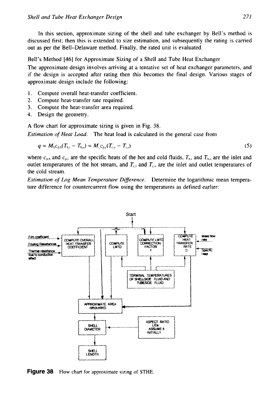
1.
Compute overall heat-transfer coefficient.
2.
Compute heat-transfer rate required.
3.
Compute the heat-transfer area required.
4.
Design the geometry.
A
flow chart for approximate sizing is given in Fig.
38.
Estimation
of
Heat
Load.
The heat load is calculated in the general case from
where
Cp,h
and
cp,c
are the specific heats of the hot and cold fluids,
Th,,
and
Th,(,
are the inlet and
outlet temperatures of the hot stream, and
Tc,i
and
TC,
are the inlet and outlet temperatures of
the cold stream.
Estimation
of
Log
Mean Temperature Difference.
Determine the logarithmic mean tempera-
ture difference for countercurrent flow using the temperatures as defined earlier:
Start
t
I
I
1
TERMINAL
TEMPERATURES
I
OFsrmuSroE
FLUIDAND
I
TUBESllX
FLUID
I
I
I
I
4
1t
~
APPROXIMATE
AREA
REWIROD
t
ASPECT
RATIO
DlAMElER
ASSUME
0
INlTlALLY
I
I
SHELL
Figure
38
Flow
chart
for approximate sizing
of
STHE.
272
Chapter
5
LMTD
Correction Factor.
Values of
F
can
be
found from the thermal relation charts given
in Chapter
2
for a variety of heat exchanger flow configurations. However, for estimation
purposes, a reasonable estimate may often be obtained without restoring to the charts.
1.
For a single tube pass, purely countercurrent heat exchanger,
F
=
1
.O.
2.
For a single shell with any even number of tube-side passes,
F
should be between
0.8
and
1.0.
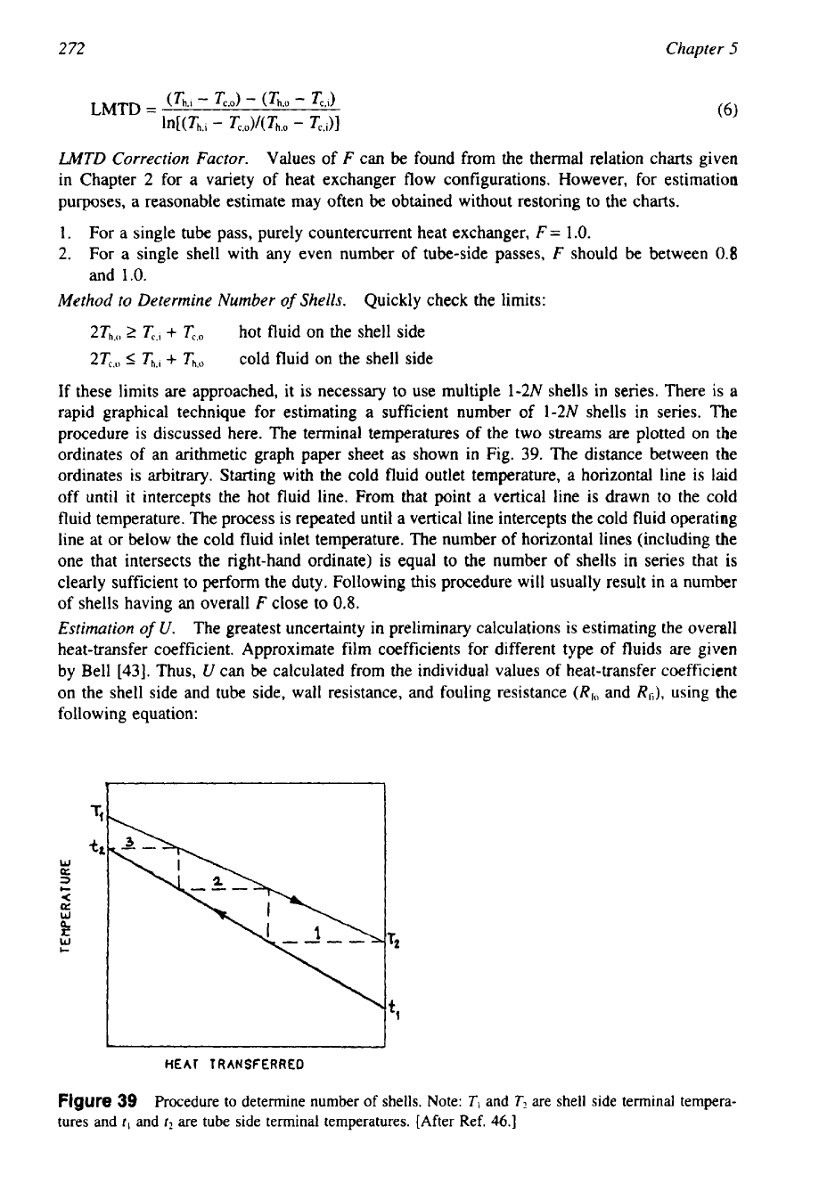
Method to Determine Number
of
Shells.
Quickly check the limits:
2Th,
2
c,l
+
Tc,o
hot fluid on the shell side
2T,,
I
Th.l
+
Th,o
cold fluid on the shell side
If these limits are approached, it is necessary to use multiple 1-2N shells in series. There is
a
rapid graphical technique for estimating a sufficient number
of
1-2N
shells in series.
The
procedure is discussed here. The terminal temperatures of the two streams are plotted on
the
ordinates of an arithmetic graph paper sheet
as
shown in Fig.
39.
The distance between the
ordinates is arbitrary. Starting with the cold fluid outlet temperature, a horizontal line is laid
off until it intercepts the hot fluid line.
From
that point
a
vertical line is drawn to the cold
fluid temperature. The process is repeated until
a
vertical line intercepts
the
cold fluid operating
line at or below the cold fluid inlet temperature. The number
of
horizontal lines (including the
one that intersects the right-hand ordinate) is equal to the number of shells in series that
is
clearly sufficient to perform the duty. Following this procedure will usually result in a number
of
shells having an overall
F
close to
0.8.
Estimation
of
U.
The greatest uncertainty in preliminary calculations is estimating the overall
heat-transfer coefficient. Approximate film coefficients for different type
of
fluids are given
by Bell
[43].
Thus,
U
can
be
calculated from the individual values of heat-transfer coefficient
on the shell side and tube side, wall resistance, and fouling resistance
(Rfo
and
Eh),
using the
following equation:
W
U
3
c
<
a
W
?
W
c
HEAT
TRANSFERRED
Figure
39
Procedure to determine number of shells. Note:
T,
and
T2
are shell side terminal tempera-
tures and
?,
and
t2
are tube side terminal temperatures. [After Ref.
46.1
Shell and Tube Heat Exchanger Design
2
73
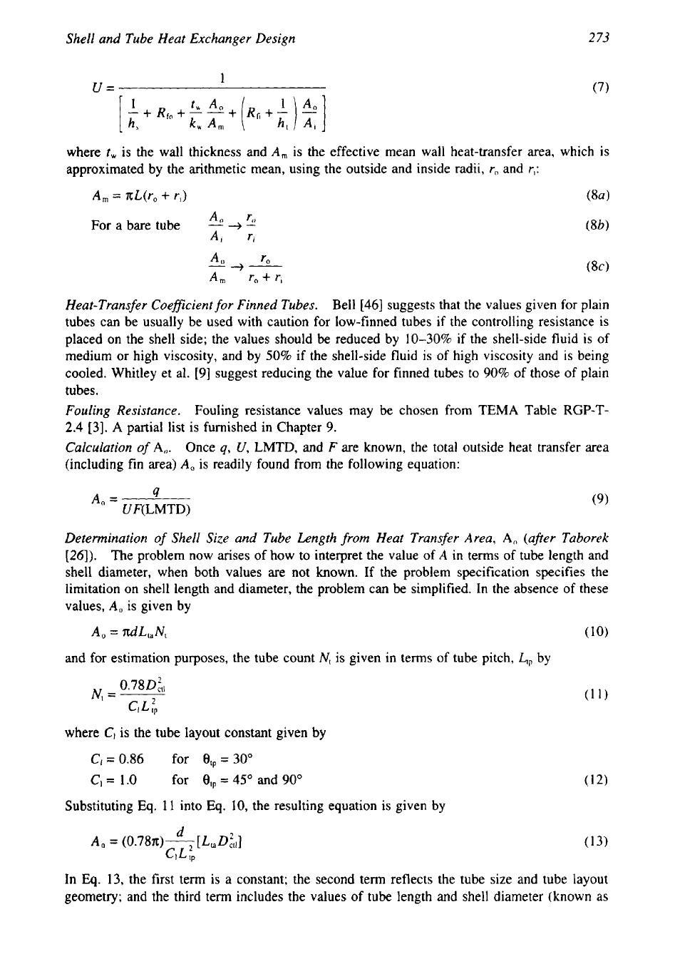
1
U=
(7)
where
t,
is the wall thickness and
A,
is the effective mean wall heat-transfer area, which is
approximated by the arithmetic mean, using the outside and inside radii,
r,
and
r,:
A,
=
nL(ro
+
r,)
An
ro
For a bare tube
-
+
-
Ai
ri
A0
r0
--+-
A,,,
ro
+
ri
Heat-Transfer Coeficient
for
Finned Tubes.
Bell
[46]
suggests that the values given for plain
tubes can be usually be used with caution for low-finned tubes if the controlling resistance is
placed on the shell side; the values should be reduced by 10-30% if the shell-side fluid is of
medium or high viscosity, and by
50%
if the shell-side fluid is of high viscosity and
is
being
cooled. Whitley et al.
[9]
suggest reducing the value for finned tubes to
90%
of those of plain
tubes.
Fouling Resistance.
Fouling resistance values may be chosen from
TEMA
Table
RGP-T-
2.4
[3].
A
partial list is furnished in Chapter
9.
Calculation
of
A,.
Once
q,
U,
LMTD,
and
F
are known, the total outside heat transfer area
(including fin area)
A,
is readily found from the following equation:
A,
=
4
UF(
LMTD)
(9)
Determination
of
Shell Size and Tube Length from Heat Transfer Area,
A,
(after Taborek
124).
The problem now arises of how to interpret the value of
A
in terms of tube length and
shell diameter, when both values are not
known.
If the problem specification specifies the
limitation on shell length and diameter, the problem can be simplified. In the absence
of
these
values,
A,
is given by
A,
=
ndL,N,
(10)
and for estimation purposes, the tube count
Nt
is given in terms of tube pitch,
LP
by
where
Cl
is the tube layout constant given by
C,
=
0.86
for
et,
=
30"
C1
=
1.0 for
8,,
=
45'
and
90"
Substituting Eq.
11
into
Eq.
10,
the resulting equation is given by
d
A
,
=
(0.78n)
7
[
L
D
:,I]
CI
L
tp
In
Eq.
13,
the first term is a constant; the second term reflects the tube size and tube layout
geometry; and the third term includes the values of tube length and shell diameter (known as