Jackson M.J. Micro and Nanomanufacturing
Подождите немного. Документ загружается.

422 Micro- and Nanomanufacturing
2.5 1
H.
3 1.5
H
0)
£
I n
r
0.5
I I I I I I
0 2 4 6 8 10 12
Non-dimensional distance from nozzle exit (X/De)
0.3mm M.L.N.
•0.1mm M.L.N.
0.2mm M.L.N.
-0.05mm M.L.N.
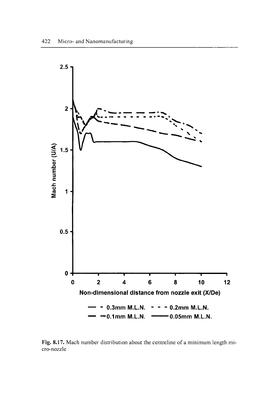
Fig. 8.17. Mach number distribution about the centreline of a minimum length mi-
cro-nozzle
Laser Micro- and Nanofabrication 423
When the highly under expansion condition is reached, the pres-
ence of a Mach shock disc exerts a large penalty on the centerline
pressure distribution. The loss increases with increasing exit Mach
number. The downstream exit Mach number distribution is not sig-
nificantly increased by raising inlet pressure once the Mach shock
disc forms. Sonic nozzles reach this condition very quickly with
inlet pressures as low as 2.6 bar pressure Therefore, the location of
stand-off distance becomes extremely critical. Conversely, the con-
vergent-divergent nozzle is under-expanded slightly in comparison
with the sonic nozzle, but the Mach number fluctuation is still sig-
nificant for laser micro-machining applications and applications
where surface roughness is the governing factor. M.L.N.s provide
the best possible results with uniform potential cores and very small
fluctuations in Mach number distribution (Figure 8.17).
Validation of IVI.L.N. Contours
Predictions of supersonic nozzle flow structures using the M.O.C.
inviscid contours were solved using a C.F.D. linear finite volume
method. The turbulence model used was the re-normalized group-
based (R.N.G.) k-6 model, derived from the instantaneous Navier-
Stokes equations. The near-wall treatment was in non-equilibrium.
The geometry and grid were drawn in the pre-processor using non-
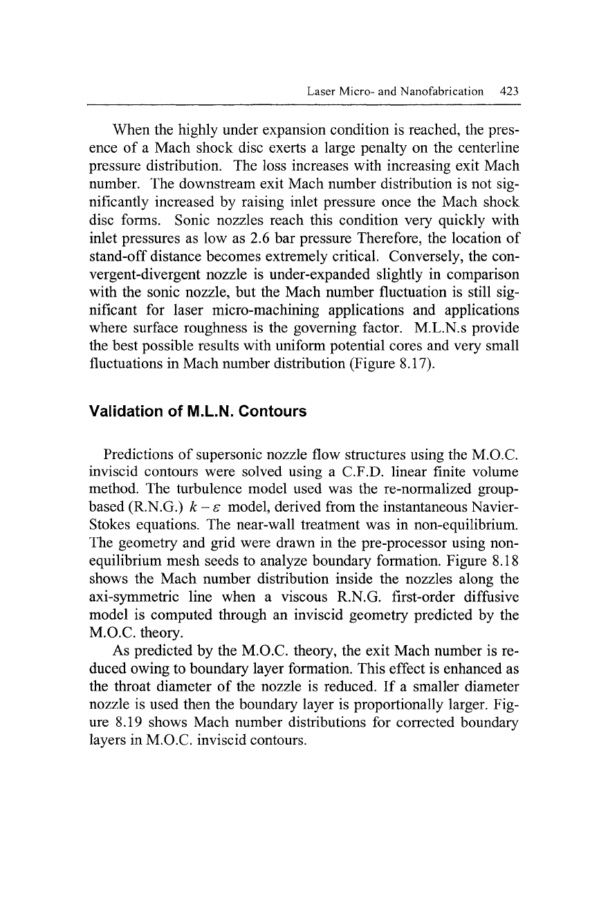
equilibrium mesh seeds to analyze boundary formation. Figure 8.18
shows the Mach number distribution inside the nozzles along the
axi-symmetric line when a viscous R.N.G. first-order diffusive
model is computed through an inviscid geometry predicted by the
M.O.C. theory.
As predicted by the M.O.C. theory, the exit Mach number is re-
duced owing to boundary layer formation. This effect is enhanced as
the throat diameter of the nozzle is reduced. If a smaller diameter
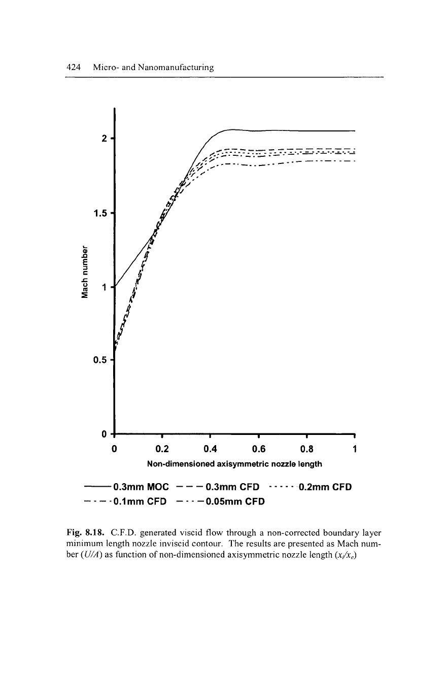
nozzle is used then the boundary layer is proportionally larger. Fig-
ure 8.19 shows Mach number distributions for corrected boundary
layers in M.O.C. inviscid contours.
424 Micro- and Nanomanufacturing
0.2 0.4 0.6 0.8
Non-dimensioned axisymmetric nozzle length
-0.3mm MOC -
•0.1mm CFD -
0.3mm
CFD
•0.05mm CFD
0.2mm
CFD
Fig. 8.18. C.F.D. generated viscid flow through a non-corrected boundary layer
minimum length nozzle inviscid contour. The results are presented as Mach num-
ber (U/A) as function of non-dimensioned axisymmetric nozzle length (x/Xe)
Laser Micro- and Nanofabrication
425
I
I I I
0.2 0.4 0.6 0.8
Non-dimensioned axisymmetric nozzle length
•0.3mm
MOC -
"0.1mm
CFD -
0.3mm
CFD
-0.05mm
CFD
0.2mm
CFD
Fig. 8.19. C.F.D. generated viscid flow through
a
corrected boundary layer mini-
mum length nozzle inviscid contour.
The
results
are
presented
as
Mach number
(U/A)
as
function
of
non-dimensioned axisymmetric nozzle length (x/Xe)
426 Micro- and Nanomanufacturing
When the inviscid contour is displaced by the displacement
thickness, all contours from the M.O.C. are representative of C.F.D.
flow propagation predictions. If the flow is supersonic, especially at
high Mach numbers, a second order diffusion model must be used to
highlight areas of interest, i.e., shock capturing, boundary layer in-
formation, etc. The M.O.C. has provided a very accurate method of
predicting supersonic nozzle contours for both de Laval and
M.L.N.s. M.L.N.s offer many advantages over de Laval, not only
due to its small scale in contrast to de Laval, but because boundary
layer formation in M.L.N.s is at a minimum level. This is advanta-
geous when designing supersonic micro-nozzles allowing nozzle di-
ameters to be as small as 50 |Lim.
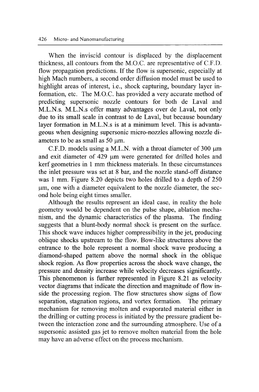
C.F.D. models using a M.L.N, with a throat diameter of 300 |Lim
and exit diameter of 429 |Lim were generated for drilled holes and
kerf geometries in 1 mm thickness materials. In these circumstances
the inlet pressure was set at 8 bar, and the nozzle stand-off distance
was 1 mm. Figure 8.20 depicts two holes drilled to a depth of 250
|um, one with a diameter equivalent to the nozzle diameter, the sec-
ond hole being eight times smaller.
Although the results represent an ideal case, in reality the hole
geometry would be dependent on the pulse shape, ablation mecha-
nism, and the dynamic characteristics of the plasma. The finding
suggests that a blunt-body normal shock is present on the surface.
This shock wave induces higher compressibility in the jet, producing
oblique shocks upstream to the flow. Bow-like structures above the
entrance to the hole represent a normal shock wave producing a
diamond-shaped pattern above the normal shock in the oblique
shock region. As flow properties across the shock wave change, the
pressure and density increase while velocity decreases significantly.
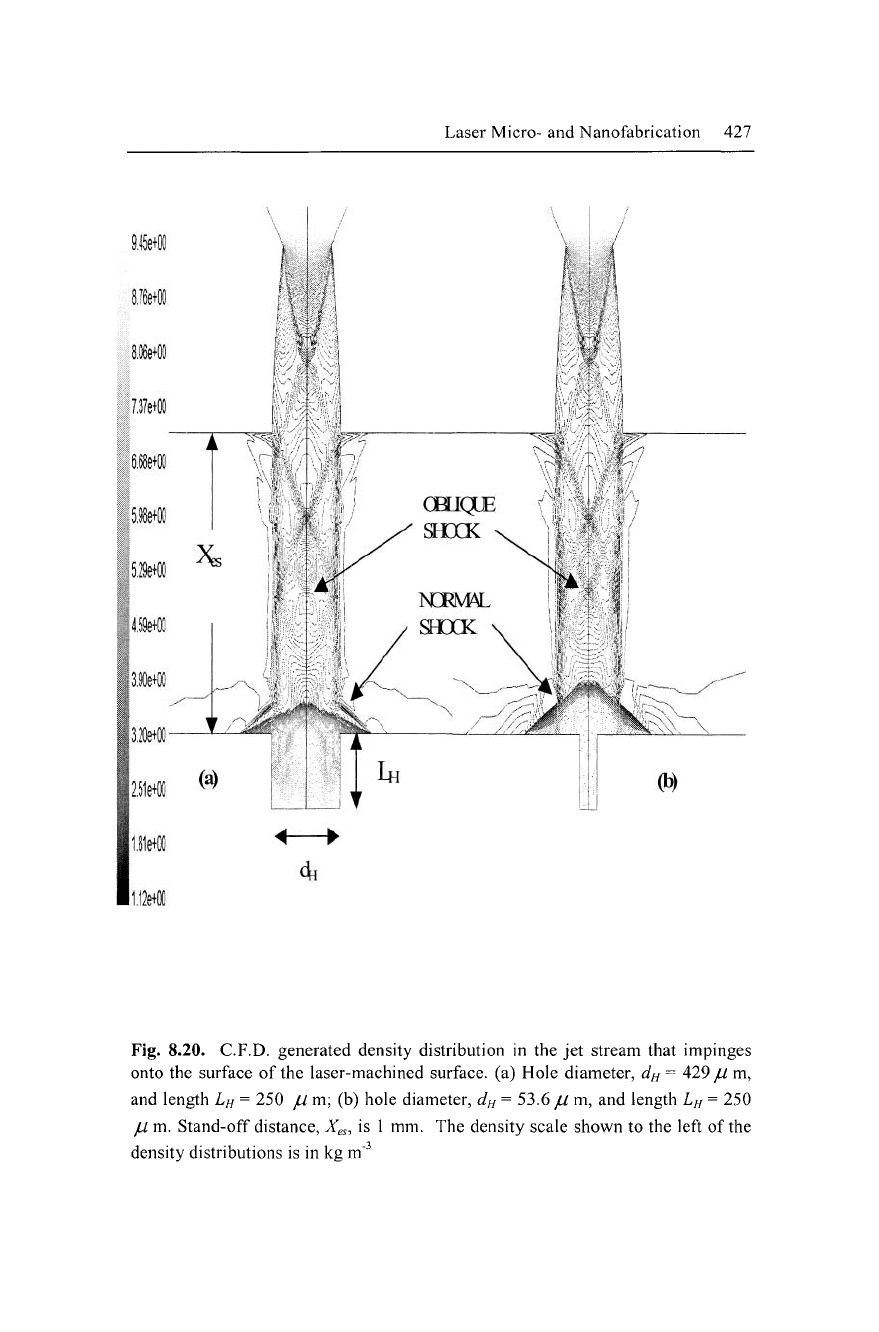
This phenomenon is further represented in Figure 8.21 as velocity
vector diagrams that indicate the direction and magnitude of flow in-
side the processing region. The flow structures show signs of flow
separation, stagnation regions, and vortex formation. The primary
mechanism for removing molten and evaporated material either in
the drilling or cutting process is initiated by the pressure gradient be-
tween the interaction zone and the surrounding atmosphere. Use of
a
supersonic assisted gas jet to remove molten material from the hole
may have an adverse effect on the process mechanism.
Laser Micro- and Nanofabrication 427
Fig. 8.20. C.F.D. generated density distribution in the jet stream that impinges
onto the surface of the laser-machined surface, (a) Hole diameter, dn = 429
jU
m,
and length 1^= 250 // m; (b) hole diameter, dH= 53.6 jUm, and length LH= 250
jU
m. Stand-off distance,
X^s,
is 1 mm. The density scale shown to the left of the
density distributions is in kg m"^
428 Micro- and Nanomanufacturing
3.00e+02
2.70e+02
2.40e+02
:^
Z10e+02
:|l.80e+02
4
I
1.50e+02
1.20e+02
9,00e+01
6.00e+01
3.00e+01
4.00e-02
1/
/^
I
/
^
fj
M i
/ ^ ^^ ^,'/
-Ml
V
\ ' %'•
r,r^'s
lE
*;7f/
(a)
'
V^"A%'
' li
(b)
Fig. 8.21. C.F.D. generated velocity profile inside a laser-drilled hole, (a) Hole
diameter, dn = 429 // m, and length L^ = 250
jU
m; (b) hole diameter, dn =
53.6 jUm, and length LH = 250 // m. The velocity scale shown to the left of the
velocity profiles is in ms"^
Laser Micro- and Nanofabrication 429
As shown in Figures 8.20 and 8.21, the supersonic jet estabHshes
a normal shock wave at the entrance to the hole, raising the pressure
just above the hole that results in a reduction of the overall pressure
gradient between atmosphere and the interaction zone. Laser cutting
and drilling processes are pressure-driven systems.
The difference in the pressure from the leading edge to the exit
of the kerf creates viscous drag, or shear stress, on the molten film
created. Ideally the pressure gradient along the kerf should exponen-
tially decay, but in reality this may not be the case. If flow is super-
sonic a sudden change in the pressure gradient creates an internal
shock formation. If the pressure gradient changes from positive to
negative then flow separation is imminent, generating vortices, or
eddies, inside the processing zone thus creating effects that are det-
rimental to the roughness of
the
processed surface.
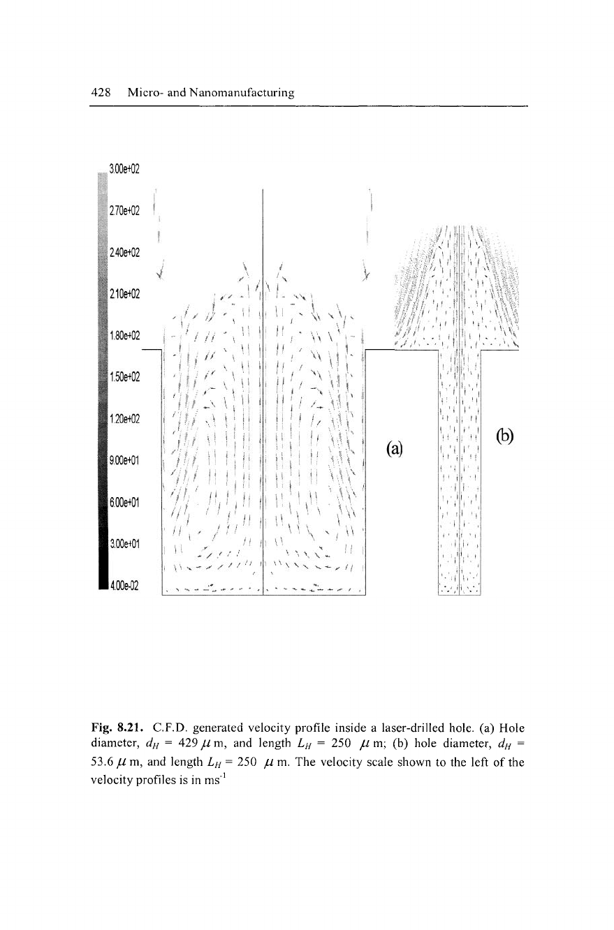
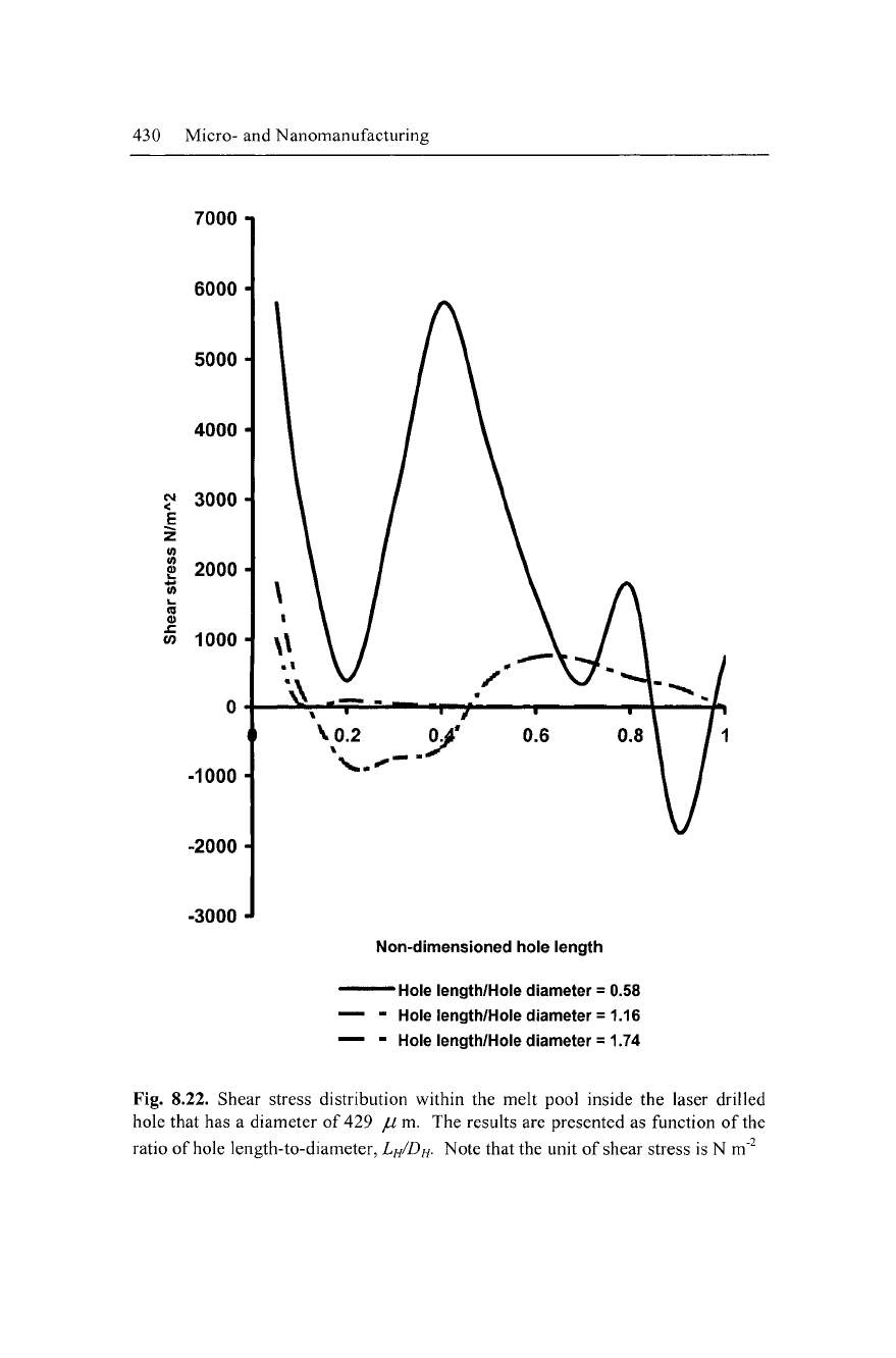
A supersonic jet is a pressure driven system, which creates shear
stresses on a molten film. The magnitude of the shear stress applied
depends on the jet velocity and the surface tension of the gas-liquid-
solid interface. For simplicity, walls in C.F.D. models are treated as
a solid surface with no external heat source. Shear stress distribu-
tions along these walls are represented by Figures 8.22 and 8.23 for
hole diameters, dn = 429 |Lxm and 53.6 |Lim, respectively. It can be
seen that the shear stress distribution inside a drilled hole depends on
its aspect ratio with respect to the nozzle diameter. As the aspect ra-
tio is increased the shear stress is reduced. As long as the shear
stress is positive there is no separation of flow; negative shear
stresses indicate a change in velocity direction of 180°. Shear stress
fluctuations indicate that there are variations in mass flow along the
surface of the wall.
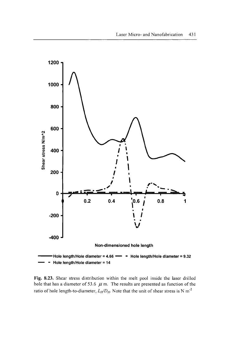
Very large fluctuations of shear stress are observed in the hole
with the smallest aspect ratio, which leads to a turbulent flow re-
gime. If the shock width is approximately the same size as the di-
ameter of the hole then shock interaction with the stagnation pres-
sure creates uneven fluid properties inside the processing zone, as
shown in Figure
8.21a.
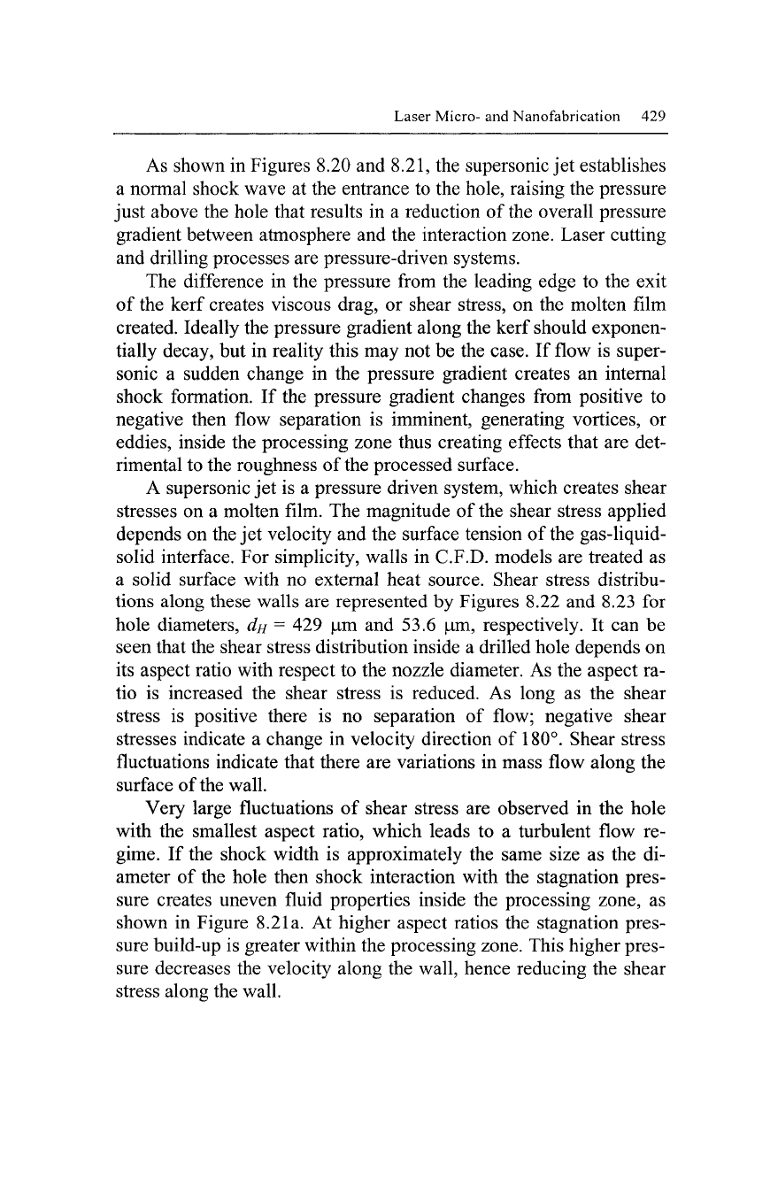
At higher aspect ratios the stagnation pres-
sure build-up is greater within the processing zone. This higher pres-
sure decreases the velocity along the wall, hence reducing the shear
stress along the wall.
430 Micro- and Nanomanufacturing
7000
1
6000
H
5000
H
4000
H
CM
<
E
z
(0
(0
o
0)
3000-
2000-
1000-
\
1
W
-1000 H
-2000
A
-3000
J
Non-dimensioned hole length
^—— Hole length/Hole diameter
= 0.58
^"
-
Hole length/Hole diameter
= 1.16
—
-
Hole length/Hole diameter
= 1.74
Fig.
8.22.
Shear stress distribution within
the
melt pool inside
the
laser drilled
hole that
has a
diameter
of
429
jU
m.
The
results
are
presented
as
function
of
the
ratio
of
hole length-to-diameter,
LH/DH-
Note that the unit
of
shear stress
is N m'^
Laser Micro- and Nanofabrication 431
1200-1
1000 H
800 H
(M
<
CO
600 H
400 H
200 H
-200 i
-400-"
Non-dimensioned hole length
-
Hole
length/Hole diameter = 4.66 — - Hole length/Hole diameter = 9.32
Hole length/Hole diameter = 14
Fig. 8.23. Shear stress distribution within the melt pool inside the laser drilled
hole that has a diameter of 53.6 // m. The results are presented as function of the
ratio of hole length-to-diameter, I///D//. Note that the unit of shear stress is N m'^