Houze Robert A., Jr. Cloud Dynamics
Подождите немного. Документ загружается.

9.2 The Squall Line with Trailing Stratiform Precipitation 369
source, supplying the cold pool with negatively buoyant air to maintain the sur-
face high-pressure area under the cold-pool head and thereby the strength of the
surface outflow current (Fig. 9.29), and as a source of vorticity for the cold pool.
In the next section, we examine the structure and dynamics of the stratiform
region, of which the rear inflow is
just
one important aspect.
9.2.3 The Stratiform Region
We have seen in
Sees, 9.2.1 and 9.2.2 that in the squall line with trailing stratiform
precipitation the dynamics of the leading convective region are intimately tied to
the trailing stratiform region, with the rear inflow current being the primary agent
by which the stratiform region feeds back to the convection. When the circulation
associated with the stratiform region appears and interacts with the convective
region, the latter is no longer controlled
just
by the large-scale undisturbed envi-
ronment but is controlled by the stratiform region dynamics as well. We will now
examine the mesoscale circulation of the stratiform region, insofar as is possible
from available observations and modeling results.
9.2.3.1 Upward
Air
Motion and Precipitation
Development in the Stratiform Cloud
We begin by looking at the results of a model simulation. In Fig. 9.25, we saw
the time-averaged structure of a model simulation of a squall line with a trailing
stratiform region. A realistic convective region was simulated but no ice was
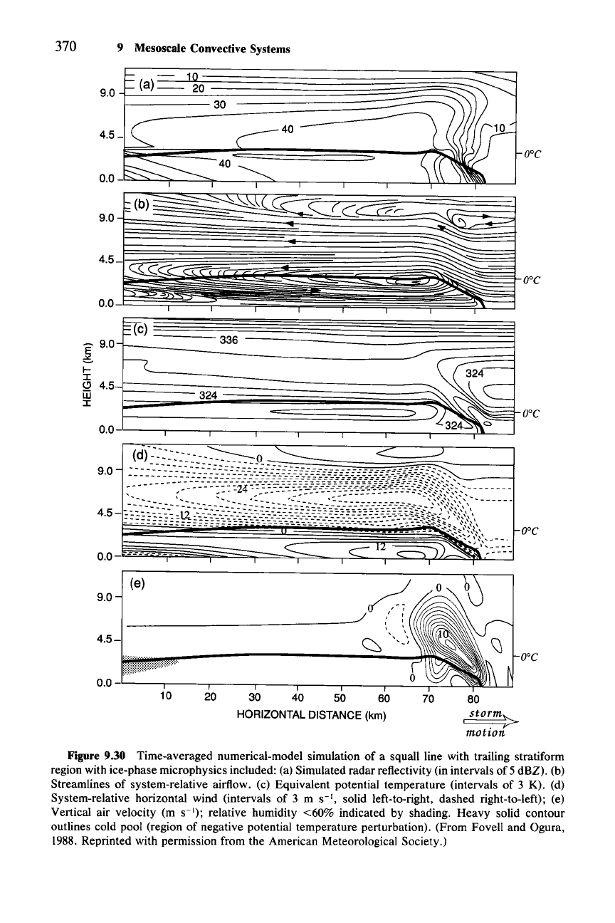
allowed to form, and a realistic stratiform region did not appear. In Fig. 9.30, we
show a time-averaged line structure for the same model but with a scheme for
representing the ice-phase microphysics included. A bulk microphysical scheme
of the type described in Sec. 3.6.2 was used in the water-continuity equations. The
only form of precipitating ice allowed to form was snow.
256 As can be seen from
Fig. 9.30a, a qualitatively realistic radar-echo pattern was obtained. The region of
precipitation reaching the surface extends across a horizontal distance of about 80
km. A radar bright band and secondary maximum of surface precipitation inten-
sity are found in the stratiform region. The structure of the precipitation is very
similar to that in Fig. 9.13. The time-averaged kinematic and thermodynamic
structure in Fig. 9.30b and c is not qualitatively different from that seen in the no-
ice case in Fig. 9.25. There are some quantitative differences, however, and the
case with ice included compares very well with data. For example, the radar
reflectivity and vertical velocity fields derived from Doppler radar data in Fig. 9.31
are nearly identical to the model fields in Fig. 9.30a and e. The observed case in
Fig. 9.31 was obtained as a composite of several volumes of Doppler radar obser-
vations centered at different locations and times within the mesoscale system. All
the data in a 60-km-wide strip oriented perpendicular to the convective line and
extending across the system were combined, averaged, and filtered to obtain the
256 Less realistic results were obtained when graupel was allowed to form because graupel falls out
too quickly.
370 9 Mesoscale Convective Systems
0.0-
o-c
E 9.0
6
t-
:I:
(!) 4.5
m
:I:
0.0
!§Tc)
336
Ie-
~24-
324
~
~C
...--
~
)~~
ire
(e)
9.0
4.5-
d
_________________
J /
~
'" "
~
<:»
.J
o-c
o-c
10
20 30 40 50 60
HORIZONTAL
DISTANCE
(km)
70
80
I
sto~m>
mohon
Figure 9.30 Time-averaged numerical-model simulation of a squall line with trailing stratiform
region with ice-phase microphysics included: (a) Simulated radar reflectivity (in intervals of 5 dBZ). (b)
Streamlines of system-relative airflow. (c) Equivalent potential temperature (intervals of 3 K). (d)
System-relative horizontal wind (intervals of 3 m
S-I,
solid left-to-right, dashed right-to-left); (e)
Vertical air velocity (m
S-I);
relative humidity <60% indicated by shading. Heavy solid contour
outlines cold pool (region of negative potential temperature perturbation). (From Fovell and Ogura,
1988. Reprinted with permission from the American Meteorological Society.)
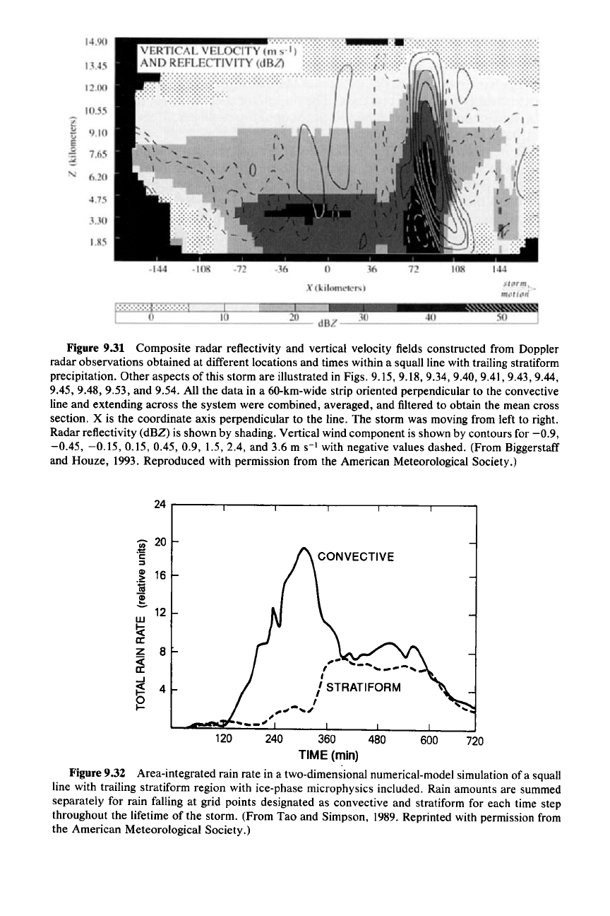
Figure 9.31 Composite radar reflectivity and vertical velocity fields constructed from Doppler
radar observations obtained at different locations and times within a squall line with trailing stratiform
precipitation. Other aspects of this storm are illustrated in Figs. 9.15, 9.18,9.34,9.40,9.41,9.43,9.44,
9.45,9.48,9.53,
and 9.54. All the data in a 60-km-wide strip oriented perpendicular to the convective
line and extending across the system were combined, averaged, and filtered to obtain the mean cross
section. X is the coordinate axis perpendicular to the line. The storm was moving from left to right.
Radar reflectivity (dBZ) is shown by shading. Vertical wind component is shown by contours for
-0.9,
-0.45, -0.15,
0.15, 0.45, 0.9, 1.5, 2.4, and 3.6 m
S-l
with negative values dashed. (From Biggerstaff
and Houze, 1993. Reproduced with permission from the American Meteorological Society.)
720
600
CONVECTIVE
,-
..
,
---
.....
_
...
-,
,
I STRATIFORM
I
,,..,,-
....
~
---"
120
24
'iii'
20
.~
c:
:::I
Gl
16
.~
iii
!
12
w
!;;(
II:
Z
8
<
II:
..J
~
4
~
240 360 480
TIME (min)
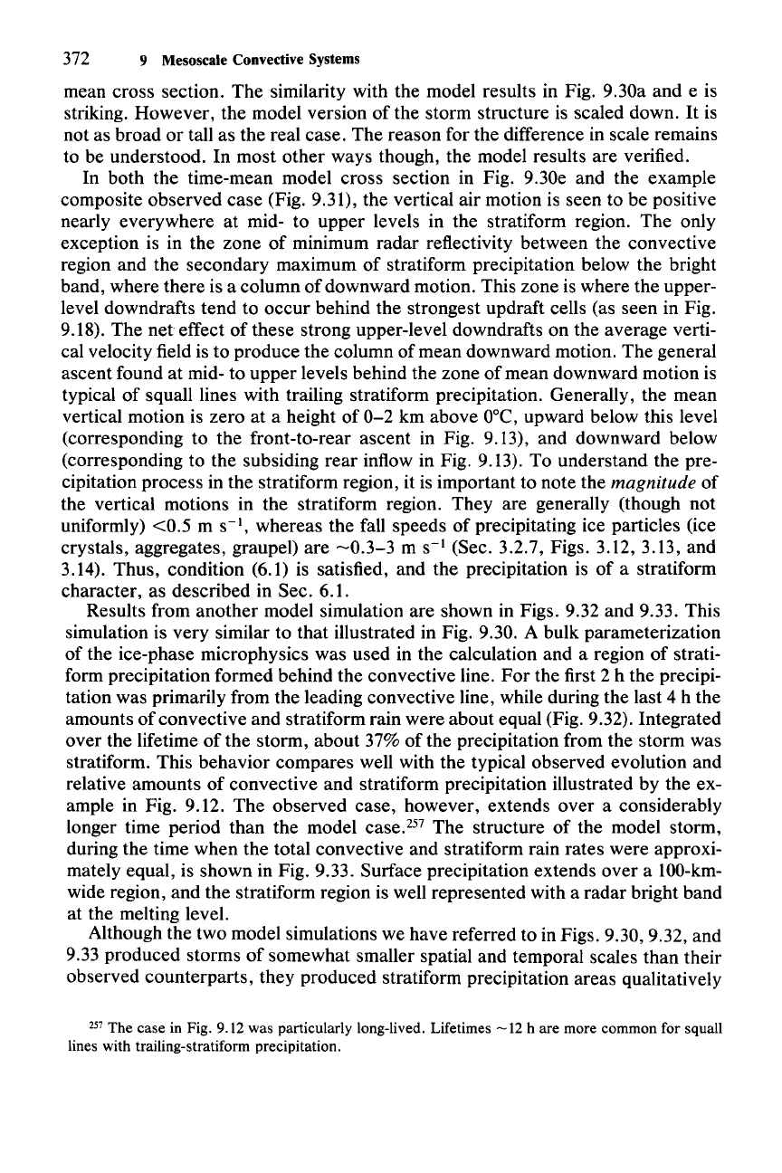
Figure 9.32 Area-integrated rain rate in a two-dimensional numerical-model simulation of a squall
line with trailing stratiform region with ice-phase microphysics included. Rain amounts are summed
separately for rain falling at grid points designated as convective and stratiform for each time step
throughout the lifetime of the storm. (From Tao and Simpson, 1989. Reprinted with permission from
the American Meteorological Society.)
372 9 Mesoscale Convective Systems
mean cross section. The similarity with the model results in Fig. 9.30a and e is
striking. However, the model version of the storm structure is scaled down.
It
is
not as broad or tall as the real case. The reason for the difference in scale remains
to be understood. In most other ways though, the model results are verified.
In both the time-mean model cross section in Fig. 9.30e and the example
composite observed case (Fig. 9.31), the vertical air motion is seen to be positive
nearly everywhere at mid- to upper levels in the stratiform region. The only
exception is in the zone of minimum radar reflectivity between the convective
region and the secondary maximum of stratiform precipitation below the bright
band, where there is a column of downward motion. This zone is where the upper-
level downdrafts tend to occur behind the strongest updraft cells (as seen in Fig.
9.18). The
net
effect of these strong upper-level downdrafts on the average verti-
cal velocity field is to produce the column of mean downward motion. The general
ascent found at mid- to upper levels behind the zone of mean downward motion is
typical of squall lines with trailing stratiform precipitation. Generally, the mean
vertical motion is zero at a height of
0-2
km above
O°C,
upward below this level
(corresponding to the front-to-rear ascent in Fig. 9.13), and downward below
(corresponding to the subsiding rear inflow in Fig. 9.13). To understand the pre-
cipitation process in the stratiform region, it is important to note the
magnitude of
the vertical motions in the stratiform region. They are generally (though not
uniformly) <0.5 m
S-I,
whereas the fall speeds of precipitating ice particles (ice
crystals, aggregates, graupel) are
-0.3-3
m
S-1
(Sec. 3.2.7, Figs. 3.12, 3.13, and
3.14). Thus, condition (6.1) is satisfied, and the precipitation is of a stratiform
character, as described in Sec. 6.1.
Results from another model simulation are shown in Figs. 9.32 and 9.33. This
simulation is very similar to that illustrated in Fig. 9.30. A bulk parameterization
of the ice-phase microphysics was used in the calculation and a region of strati-
form precipitation formed behind the convective line.
For
the first 2 h the precipi-
tation was primarily from the leading convective line, while during the last 4 h the
amounts of convective and stratiform rain were about equal (Fig. 9.32). Integrated
over the lifetime of the storm, about 37% of the precipitation from the storm was
stratiform. This behavior compares well with the typical observed evolution and
relative amounts of convective and stratiform precipitation illustrated by the ex-
ample in Fig. 9.12. The observed case, however, extends over a considerably
longer time period than the model case.P? The structure of the model storm,
during the time when the total convective and stratiform rain rates were approxi-
mately equal, is shown in Fig. 9.33. Surface precipitation extends over a 100-km-
wide region, and the stratiform region is well represented with a radar bright band
at the melting level.
Although the two model simulations we have referred to in Figs. 9.30,9.32, and
9.33 produced storms of somewhat smaller spatial and temporal scales than their
observed counterparts, they produced stratiform precipitation areas qualitatively
257 The case in Fig. 9.12 was particularly long-lived. Lifetimes
-12
h are more common for squall
lines with trailing-stratiform precipitation.
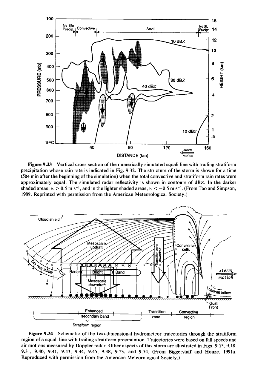
Figure 9.33 Vertical cross section of the numerically simulated squall line with trailing stratiform
precipitation whose rain rate is indicated in Fig. 9.32. The structure of the storm is shown for a time
(504 min after the beginning
ofthe
simulation) when the total convective and stratiform rain rates were
approximately equal. The simulated radar reflectivity is shown in contours of dBZ. In the darker
shaded areas,
w > 0.5 m
S-I,
and in the lighter shaded areas, w <
-0.5
m
S-I.
(From Tao and Simpson,
1989. Reprinted with permission from the American Meteorological Society.)
Cloud shield !
Gust
Front
region
Convective
zone
Transition
v
,, se,condary band
I Enhanced
Stratiform region
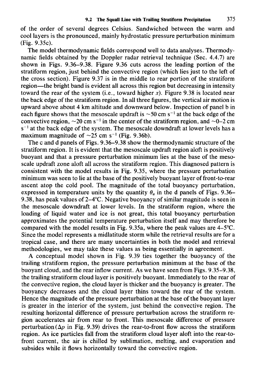
Figure 9.34 Schematic of the two-dimensional hydrometeor trajectories through the stratiform
region of a squall line with trailing stratiform precipitation. Trajectories were based on fall speeds and
air motions measured by Doppler radar. Other aspects of this storm are illustrated in Figs. 9.15, 9.18,
9.31, 9.40, 9.41, 9.43, 9.44, 9.45, 9.48, 9.53, and 9.54. (From Biggerstaff and Houze, 1991a.
Reproduced with permission from the American Meteorological Society.)
9.2 The Squall Line with Trailing Stratiform Precipitation
375
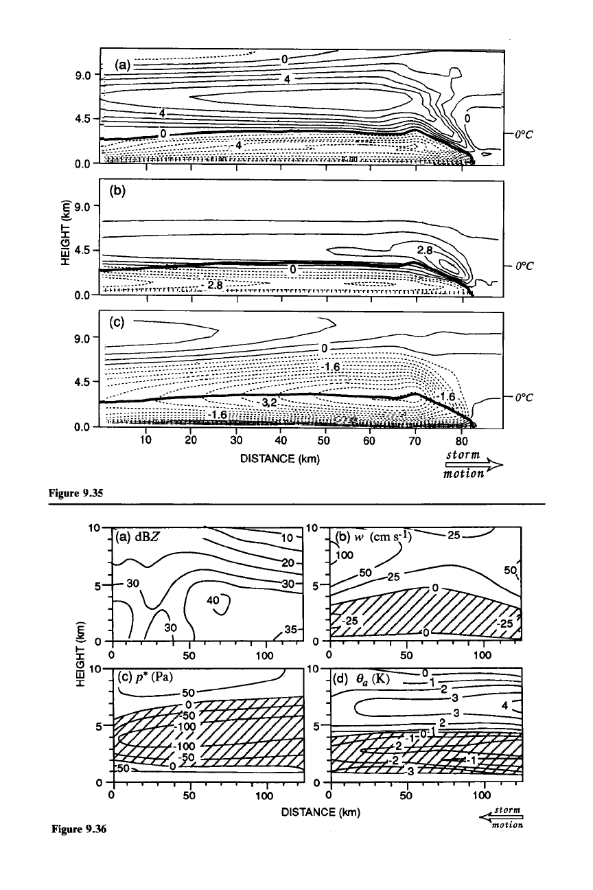
of the order of several degrees Celsius. Sandwiched between the warm and
cool layers is the pronounced, mainly hydrostatic pressure perturbation minimum
(Fig. 9.35c).
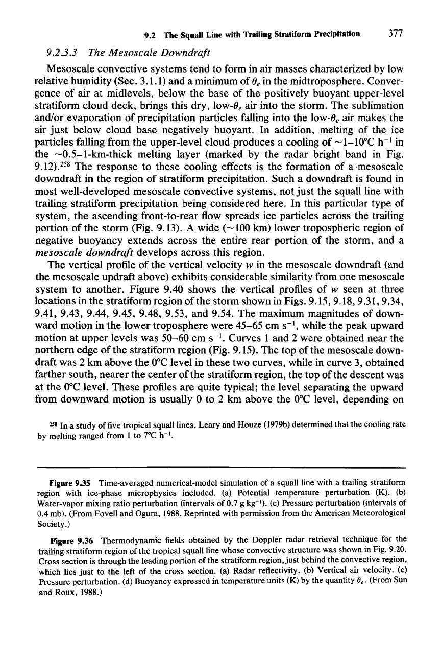
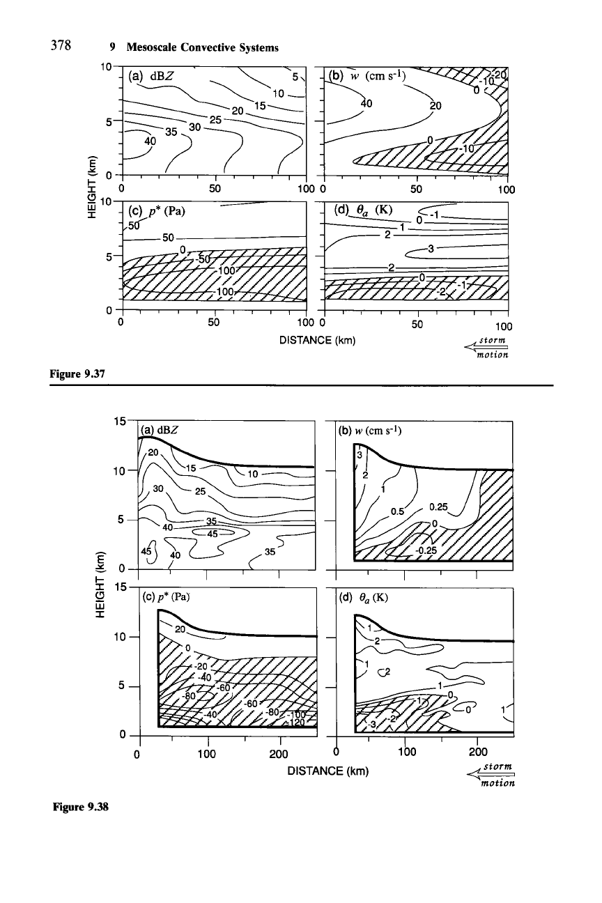
The model thermodynamic fields correspond well to data analyses. Thermody-
namic fields obtained by the Doppler radar retrieval technique (Sec. 4.4.7) are
shown in Figs. 9.36-9.38. Figure 9.36 cuts across the leading portion of the
stratiform region,
just
behind the convective region (which lies just to the left of
the cross section). Figure 9.37 is in the middle to rear portion of the stratiform
region-the
bright band is evident all across this region but decreasing in intensity
toward the rear of the system (i.e., toward higher
x). Figure 9.38 is located near
the back edge
ofthe
stratiform region. In all three figures, the vertical air motion is
upward above about 4 km altitude and downward below. Inspection of panel b in
each figure shows that the mesoscale updraft is
-50
em
S-1
at the back edge
ofthe
convective region,
-20
em
S-1
in the center of the stratiform region, and
-0-2
em
S-1
at the back edge of the system. The mesoscale downdraft at lower levels has a
maximum magnitude of
-25
cm
S-I
(Fig. 9.36b).
The c and d panels of Figs. 9.36-9.38 show the thermodynamic structure of the
stratiform region.
It
is evident that the mesoscale updraft region aloft is positively
buoyant and that a pressure perturbation minimum lies at the base of the meso-
scale updraft zone aloft all across the stratiform region. This diagnosed pattern is
consistent with the model results in Fig. 9.35, where the pressure perturbation
minimum was seen to lie at the base of the positively buoyant layer offront-to-rear
ascent atop the cold pool. The magnitude of the total buoyancy perturbation,
expressed in temperature units by the quantity
(Ja in the d panels of Figs. 9.36-
9.38, has peak values of 2-4°C. Negative buoyancy of similar magnitude is seen in
the mesoscale downdraft at lower levels. In the stratiform region, where the
loading of liquid water and ice is not great, this total buoyancy perturbation
approximates the potential temperature perturbation itself and may therefore be
compared with the model results in Fig. 9.35a, where the peak values are 4-5°C.
Since the model represents a midlatitude storm while the retrieval results are for a
tropical case, and there are many uncertainties in both the model and retrieval
methodologies, we may take these values as being essentially in agreement.
A conceptual model shown in Fig. 9.39 ties together the buoyancy of the
trailing stratiform region, the pressure perturbation minimum at the base of the
buoyant cloud, and the rear inflow current. As we have seen from Figs. 9.35-9.38,
the trailing stratiform cloud layer is positively buoyant. Immediately to the rear of
the convective region, the cloud layer is thicker and the buoyancy is greater. The
buoyancy decreases and the cloud layer thins toward the rear of the system.
Hence the magnitude of the pressure perturbation at the base of the buoyant layer
is greater in the interior of the system,
just
behind the convective region. The
resulting horizontal difference of pressure perturbation across the stratiform re-
gion accelerates air from rear to front. This mesoscale difference of pressure
perturbation
(Ap
in Fig. 9.39) drives the rear-to-front flow across the stratiform
region. As ice particles fall from the stratiform cloud layer aloft into the rear-to-
front current, the air is chilled by sublimation, melting, and evaporation and
subsides while it flows horizontally toward the convective region.
374 9 Mesoscale Convective Systems
quite similar to those observed. We have seen this similarity in both the structure
of their radar reflectivity and the evolution and amount of surface precipitation,
and we have noted that this similarity is achieved only when the ice-phase micro-
physics are included in the model simulations. Thus, it must be concluded that the
production of ice in the upper levels of the convective region and its advection
rearward by the front-to-rear ascent are crucial to the formation of the trailing
stratiform region. As indicated by the horizontal wind pattern in Fig. 9.30d, slowly
falling snow particles grown in the upper levels of the convective cells in the
convective region are advected by front-to-rear flow in the manner depicted sche-
matically in Figs.
6.1lfand
9.13.
A more detailed schematic of these processes is provided in Fig. 9.34. The
trailing nimbostratus cloud deck is supplied with precipitation-sized ice particles,
which are spread across the trailing region. These particles fall (at speeds of
-1-3
m
S-I)
through the "mesoscale updraft" zone of weak vertical air motions. They
first cross the region of mean downward motion
just
behind the convective region.
In this "transition
zone,"
the mass of precipitation particles cannot increase, and
the particles partially evaporate. The more slowly falling particles from upper
levels are, however, quickly advected across the region of downward motion into
the region of the mesoscale updraft, where they grow significantly by vapor depo-
sition while continuing their slow descent to the melting layer. The upward air
motions of the order of tens of centimeters per second are great enough to con-
dense a considerable amount of vapor but small enough for all the ice particles to
fall [condition (6.1) is met]. The precipitation is stratiform in character. Before
reaching the melting layer, and possibly within it, the ice particles may aggregate
and by virtue of the large particles produced enhance the radar reflectivity inten-
sity in the bright band. The aggregation, however, does not increase the bulk mass
of the falling snow; it only changes the particle size distribution. Once melted, the
ice particles fall to the ground as rain.
As shown in Fig. 9.34, the maximum of the stratiform rain rate at the surface
below the mesoscale updraft may be attributed to the enhancement of the strati-
form precipitation by the mesoscale updraft above the melting layer. The mini-
mum in rain rate and radar reflectivity at low levels between the convective region
and the enhanced stratiform rain below the mesoscale updraft is associated with
particles falling out of convective cells but not being able to grow effectively in the
transition-zone downdraft region.
9.2.3.2 Thermodynamic Structure
of
the Stratiform Region
The thermodynamic structure of the stratiform region is also indicated by
model simulations. The perturbation fields of potential temperature, water-vapor
mixing ratio, and pressure for the time-averaged simulation of Fig. 9.30 are shown
in Fig. 9.35. A major feature is that the stratiform region is marked by a potential
temperature perturbation maximum of
-5°C
all the way to the back edge of the
storm (Fig. 9.35a). This feature is accompanied by a positive water vapor pertur-
bation (Fig. 9.35b). Lying below this warm, positively buoyant layer is a cold,
negatively buoyant layer, characterized by potential temperature perturbations
(b)
I-----------=~
E9.0
~
l-
I
C)
m4.5
I
I I I
60
70 80
storm
~otion>
Figure 9.35
100
<sto~m
mot
ion.
100
50
50
(b) w
(em
s-l)
--25
100
./
50 25
o
o
100 0
DISTANCE
(km)
100
50
50
(a)
dBZ
O+~..__.......,.......,,...,.---r-....,.._._,--r-.,...J
o
5
10....,..~
.........
---::::_-==____,1
0-r7."'":'"........,--=:::::::----;~-_r___,
!
0
I-
0
I
£2
10
w
I
5
Figure 9.36
9.2 The Squall Line with Trailing Stratiform Precipitation 377
9.2.3.3 The Mesoscale Downdraft
Mesoscale convective systems tend to form in air masses characterized by low
relative humidity (Sec. 3.1.1) and a minimum of
Oe
in the midtroposphere. Conver-
gence of air at midlevels, below the base of the positively buoyant upper-level
stratiform cloud deck, brings this dry, low-s, air into the storm. The sublimation
and/or evaporation of precipitation particles falling into the low-s, air makes the
air
just
below cloud base negatively buoyant. In addition, melting of the ice
particles falling from the upper-level cloud produces a cooling of -1-lOoC h-
I
in
the
-0.5-1-km-thick
melting layer (marked by the radar bright band in Fig.
9.12).258
The response to these cooling effects is the formation of a mesoscale
downdraft in the region of stratiform precipitation. Such a downdraft is found in
most well-developed mesoscale convective systems, not
just
the squall line with
trailing stratiform precipitation being considered here. In this particular type of
system, the ascending front-to-rear flow spreads ice particles across the trailing
portion of the storm (Fig. 9.13). A wide
(-100
km) lower tropospheric region of
negative buoyancy extends across the entire rear portion of the storm, and a
mesoscale downdraft develops across this region.
The vertical profile of the vertical velocity
w in the mesoscale downdraft (and
the mesoscale updraft above) exhibits considerable similarity from one mesoscale
system to another. Figure 9.40 shows the vertical profiles of
w seen at three
locations in the stratiform region of the storm shown in Figs. 9.15, 9.18, 9.31,9.34,
9.41, 9.43, 9.44, 9.45, 9.48, 9.53, and 9.54. The maximum magnitudes of down-
ward motion in the lower troposphere were 45-65 em
S-I,
while the peak upward
motion at upper levels was 50-60 em s
-1.
Curves 1 and 2 were obtained near the
northern edge
of
the stratiform region (Fig. 9.15). The top of the mesoscale down-
draft was 2 km above the
O°C
level in these two curves, while in curve 3, obtained
farther south, nearer the center
ofthe
stratiform region, the top
ofthe
descent was
at the
O°C
level. These profiles are quite typical; the level separating the upward
from downward motion is usually 0 to 2 km above the
O°C
level, depending on
258 In a study of five tropical squall lines, Leary and Houze (l979b) determined that the cooling rate
by melting ranged from 1 to 7°C h-
I
.
Figure 9.35 Time-averaged numerical-model simulation of a squall line with a trailing stratiform
region with ice-phase microphysics included. (a) Potential temperature perturbation (K). (b)
Water-vapor mixing ratio perturbation (intervals of 0.7 g kg:"). (c) Pressure perturbation (intervals of
0.4 mb). (From Fovell and Ogura, 1988. Reprinted with permission from the American Meteorological
Society.)
Figure 9.36 Thermodynamic fields obtained by the Doppler radar retrieval technique for the
trailing stratiform region of the tropical squall line whose convective structure was shown in Fig. 9.20.
Cross section is through the leading portion of the stratiform region,
just
behind the convective region,
which lies
just
to the left of the cross section. (a) Radar reflectivity. (b) Vertical air velocity. (c)
Pressure perturbation. (d) Buoyancy expressed in temperature units (K) by the quantity
ea'
(From Sun
and Roux, 1988.)
100
100
~
motion.
50
50
F1
1000
DISTANCE
(krn)
50
5
378 9 Mesoscale Convective Systems
10
(a)
dBZ
--..........
5,
~
",,---
10_
---
'----20
15
__
~:~~71
5:
0 50 100 0
S2
10
~-,.--------==-------,
~
(c) p* (Pa)
50
Figure 9.37
200
«
sto~m
motion
100
(b) w (em
s-I)
200
DISTANCE (km)
10
100
o
O-+---r--..-----,-------,------'
15~-----------~
10
5
~
E
46
40
35
:::.
0
I-
15
J:
CJ
(c) p* (Pa}
(d)
8
a
(K)
m
J:
10
5
Figure 9.38
