Hoffman D.M., Singh B., Thomas J.H. (Eds). Handbook of Vacuum Science and Technology
Подождите немного. Документ загружается.

654
5.2.6.3
Triodes
Chapter 5.2: Plasma Etching
PARALLEL-PLATE TRIODES
Triodes, as their name implies, are trielectrode discharge systems. In triodes, two
of the three electrodes are powered while the third electrode is normally at the
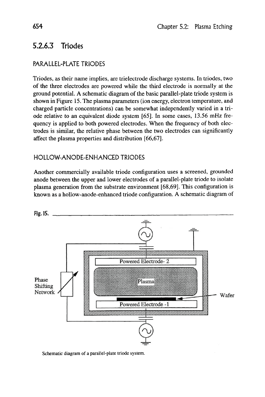
ground potential. A schematic diagram of the basic parallel-plate triode system is
shown in Figure
15.
The plasma parameters (ion energy, electron temperature, and
charged particle concentrations) can be somewhat independently varied in a tri-
ode relative to an equivalent diode system [65]. In some cases, 13.56 mHz fre-
quency is applied to both powered electrodes. When the frequency of both elec-
trodes is similar, the relative phase between the two electrodes can significantly
affect the plasma properties and distribution [66,67].
HOLLOW-ANODE-ENHANCED TRIODES
Another commercially available triode configuration uses a screened, grounded
anode between the upper and lower electrodes of a parallel-plate triode to isolate
plasma generation from the substrate environment [68,69]. This configuration is
known as a hollow-anode-enhanced triode configuration. A schematic diagram of
Fig. 15.
Phase
Shifting
Network
Wafer
Schematic diagram of
a
parallel-plate triode system.
5.2.6 Advanced Plasma Etch Reactors
655
Fig. 16.
RFl
RF
Matching
Network
;_jr
RF2
Lower
Electrode
Process
Gases In
Upper
Electrode
Helium Gas Cooling
Screen
' Anode
Process
Gases
•" Out
Under Wafer
Wafer
Hollow-anode-enhanced triode reactor configuration.
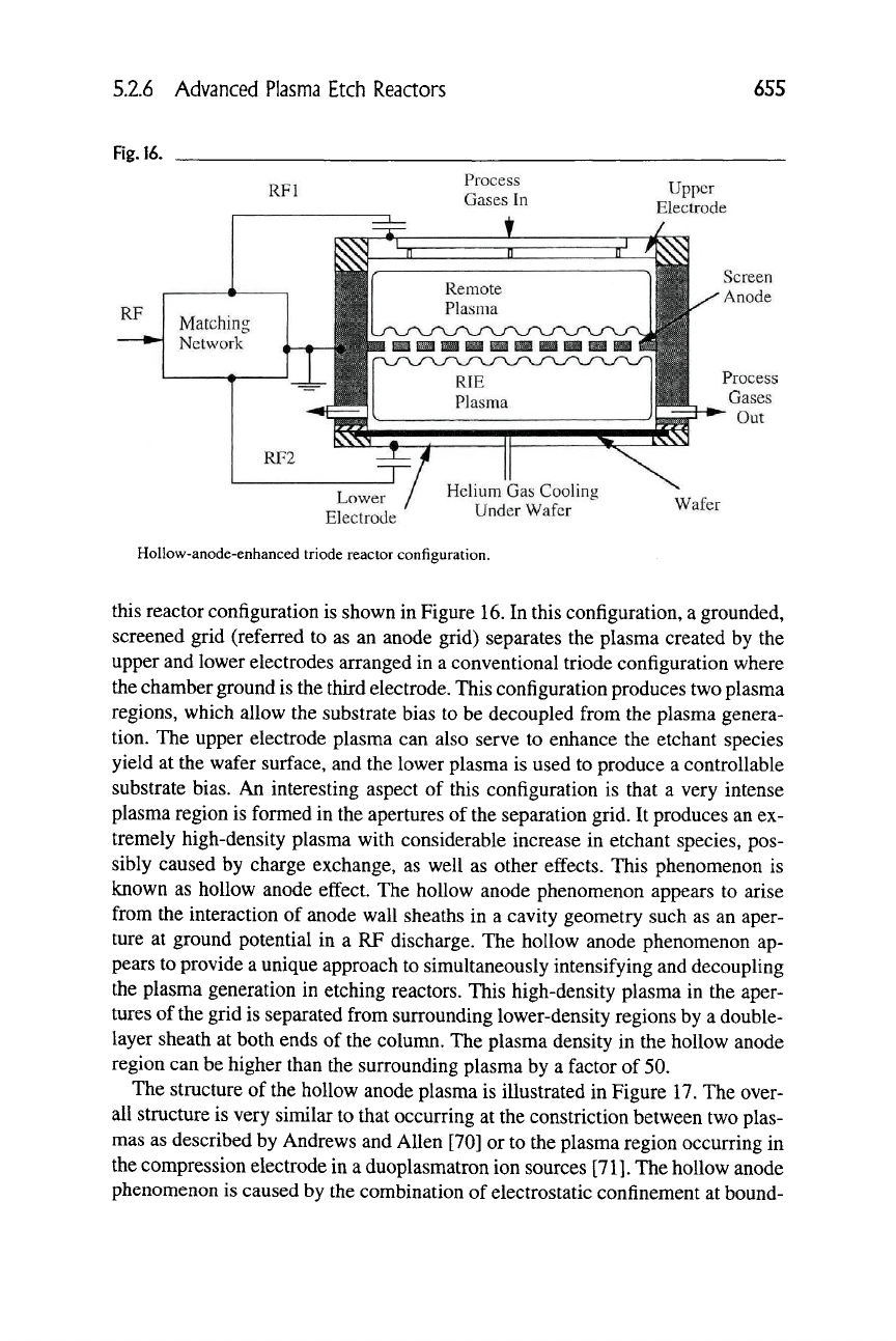
this reactor configuration is shown in Figure 16. In this configuration, a grounded,
screened grid (referred to as an anode grid) separates the plasma created by the
upper and lower electrodes arranged in a conventional triode configuration where
the chamber ground is the third electrode. This configuration produces two plasma
regions, which allow the substrate bias to be decoupled from the plasma genera-
tion. The upper electrode plasma can also serve to enhance the etchant species
yield at the wafer surface, and the lower plasma is used to produce a controllable
substrate bias. An interesting aspect of this configuration is that a very intense
plasma region is formed in the apertures of the separation grid. It produces an ex-
tremely high-density plasma with considerable increase in etchant species, pos-
sibly caused by charge exchange, as well as other effects. This phenomenon is
known as hollow anode effect. The hollow anode phenomenon appears to arise
from the interaction of anode wall sheaths in a cavity geometry such as an aper-
ture at ground potential in a RF discharge. The hollow anode phenomenon ap-
pears to provide a unique approach to simultaneously intensifying and decoupling
the plasma generation in etching reactors. This high-density plasma in the aper-
tures of the grid is separated from surrounding lower-density regions by a double-
layer sheath at both ends of the column. The plasma density in the hollow anode
region can be higher than the surrounding plasma by a factor of 50.
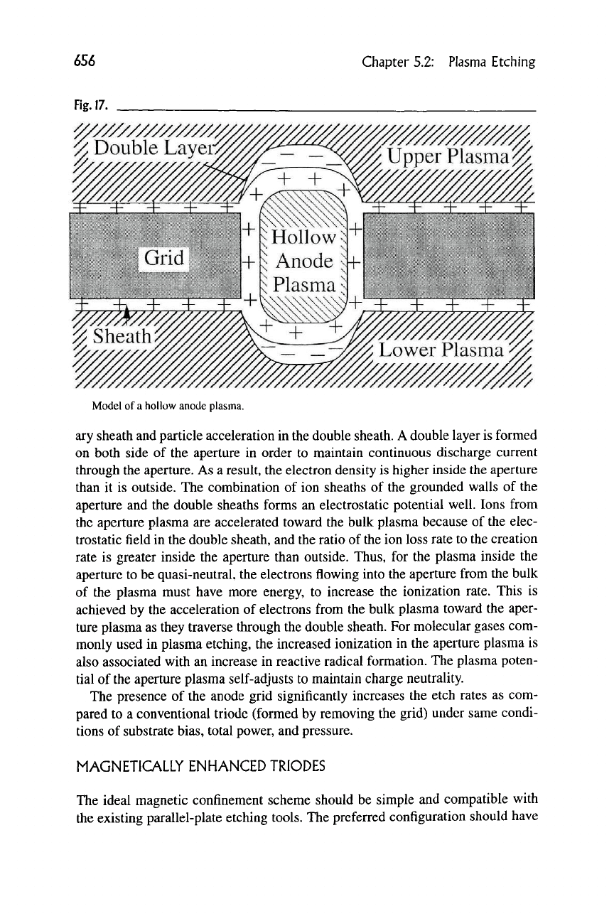
The structure of the hollow anode plasma is illustrated in Figure 17. The over-
all structure is very similar to that occurring at the constriction between two plas-
mas as described by Andrews and Allen [70] or to the plasma region occurring in
the compression electrode in a duoplasmatron ion sources
[711.
The hollow anode
phenomenon is caused by the combination of electrostatic confinement at bound-
656
Chapter 5.2: Plasma Etching
Fig.
17.
Model of
a
hollow anode plasma.
ary sheath and particle acceleration in the double sheath. A double layer is formed
on both side of the aperture in order to maintain continuous discharge current
through the aperture. As a result, the electron density is higher inside the aperture
than it is outside. The combination of ion sheaths of the grounded walls of the
aperture and the double sheaths forms an electrostatic potential well. Ions from
the aperture plasma are accelerated toward the bulk plasma because of the elec-
trostatic field in the double sheath, and the ratio of the ion loss rate to the creation
rate is greater inside the aperture than outside. Thus, for the plasma inside the
aperture to be quasi-neutral, the electrons flowing into the aperture from the bulk
of the plasma must have more energy, to increase the ionization rate. This is
achieved by the acceleration of electrons from the bulk plasma toward the aper-
ture plasma as they traverse through the double sheath. For molecular gases com-
monly used in plasma etching, the increased ionization in the aperture plasma is
also associated with an increase in reactive radical formation. The plasma poten-
tial of the aperture plasma self-adjusts to maintain charge neutrality.
The presence of the anode grid significantly increases the etch rates as com-
pared to a conventional triodc (formed by removing the grid) under same condi-
tions of substrate bias, total power, and pressure.
MAGNETICALLY ENHANCED TRIODES
The ideal magnetic confinement scheme should be simple and compatible with
the existing parallel-plate etching tools. The preferred configuration should have
S.2.6 Advanced Plasma Etch Reactors
657
Fig.
18.
Wafer
Lower Electrode !
#13.56 MHz
Power Supply
_Multipolar
Magnets
Side Electrode
Insulator
100 KHz
power Supply
Schematic of
a
commercial tri-eleclrode reactor with magnetic confinement.
all the attributes of magnetic enhancement, namely low-pressure operation, high
plasma density, low substrate bias voltage, very low magnetic field near the wafer
surface, and decoupling of plasma generation (reactive species concentration)
from the substrate bias (ion bombardment energy). Many approaches have been
proposed to decouple plasma generation from substrate bias using triode configu-
ration while using magnetic enhancement to increase etch rates at lower pres-
sures.
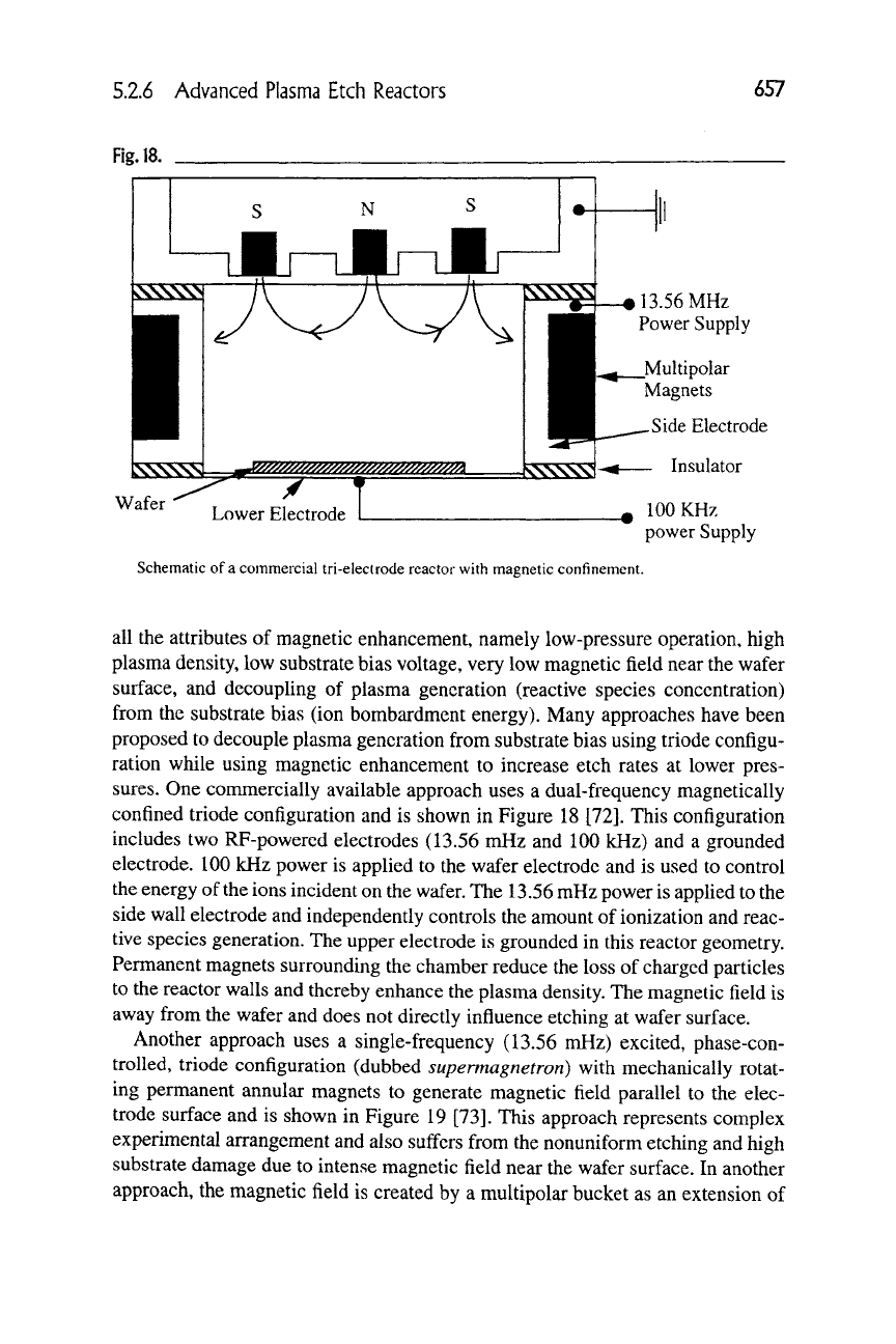
One conmiercially available approach uses a dual-frequency magnetically
confined triode configuration and is shown in Figure 18 [72]. This configuration
includes two RF-powered electrodes (13.56 mHz and 100 kHz) and a grounded
electrode. 100 kHz power is applied to the wafer electrode and is used to control
the energy of the ions incident on the wafer. The 13.56 mHz power is applied to the
side wall electrode and independently controls the amount of ionization and reac-
tive species generation. The upper electrode is grounded in this reactor geometry.
Permanent magnets surrounding the chamber reduce the loss of charged particles
to the reactor walls and thereby enhance the plasma density. The magnetic field is
away from the wafer and does not directly influence etching at wafer surface.
Another approach uses a single-frequency (13.56 mHz) excited, phase-con-
trolled, triode configuration (dubbed supermagnetron) with mechanically rotat-
ing permanent annular magnets to generate magnetic field parallel to the elec-
trode surface and is shown in Figure 19 [73]. This approach represents complex
experimental arrangement and also suffers from the nonuniform etching and high
substrate damage due to intense magnetic field near the wafer surface. In another
approach, the magnetic field is created by a multipolar bucket as an extension of
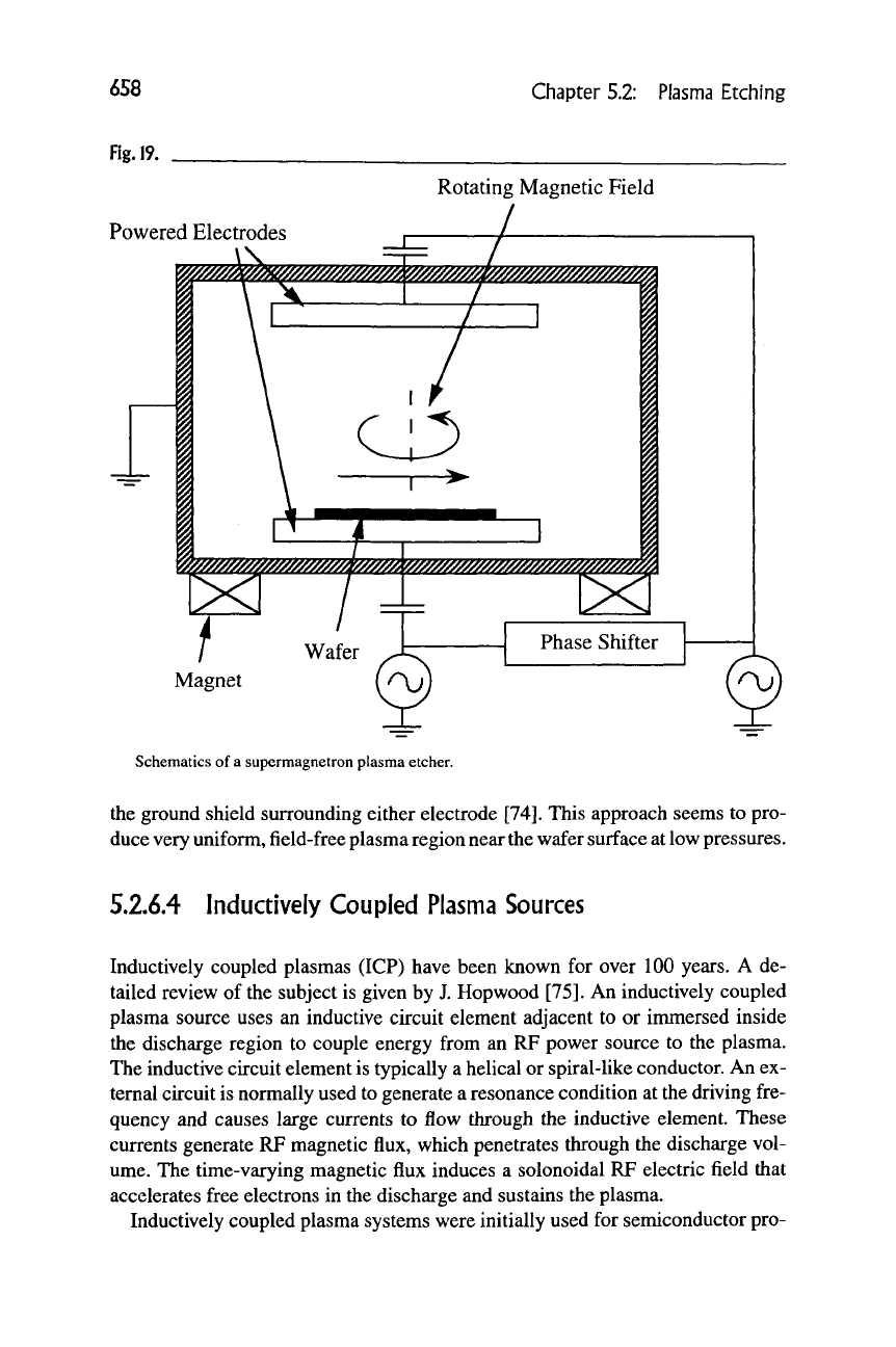
658
Chapter 5.2: Plasma Etching
Fig. 19.
Rotating Magnetic Field
Powered Electrodes
^m^/////w^^^
^;^j!j;j!s^
}
^^m
Wafer
Magnet
f ^\j)
Phase Shifter
Schematics
of
a
supermagnetron plasma etcher.
the ground shield surrounding either electrode [74]. This approach seems
to
pro-
duce very uniform, field-free plasma region near
the
wafer surface at low pressures.
5.2.6.4
Inductively Coupled Plasma Sources
Inductively coupled plasmas
(ICP)
have been known
for
over
100
years.
A de-
tailed review
of
the subject
is
given
by J.
Hop wood [75].
An
inductively coupled
plasma source uses
an
inductive circuit element adjacent
to or
inmiersed inside
the discharge region
to
couple energy from
an RF
power source
to the
plasma.
The inductive circuit element is typically
a
helical
or
spiral-like conductor. An ex-
ternal circuit is normally used to generate a resonance condition
at
the driving fre-
quency
and
causes large currents
to
flow through
the
inductive element. These
currents generate RP magnetic flux, which penetrates through
the
discharge vol-
ume.
The
time-varying magnetic flux induces
a
solonoidal
RF
electric field that
accelerates free electrons
in
the discharge
and
sustains the plasma.
Inductively coupled plasma systems were initially used
for
semiconductor pro-
5.2.6 Advanced Plasma Etch Reactors
659
cessing in a configuration known as a barrel reactor (see Section 5.2.5.2). Re-
cently, the trend toward high-rate, low-pressure, single-wafer processing has mo-
tivated the development of low-pressure ICP configurations. Very high plasma
densities (in the range of 10^^ ions/cm^) have been reported in various ICP con-
figurations
[76].
The three most common ICP configurations used today are heli-
cal inductive couplers, helical resonators, and spiral inductive couplers.
HELICAL INDUCTIVE COUPLERS
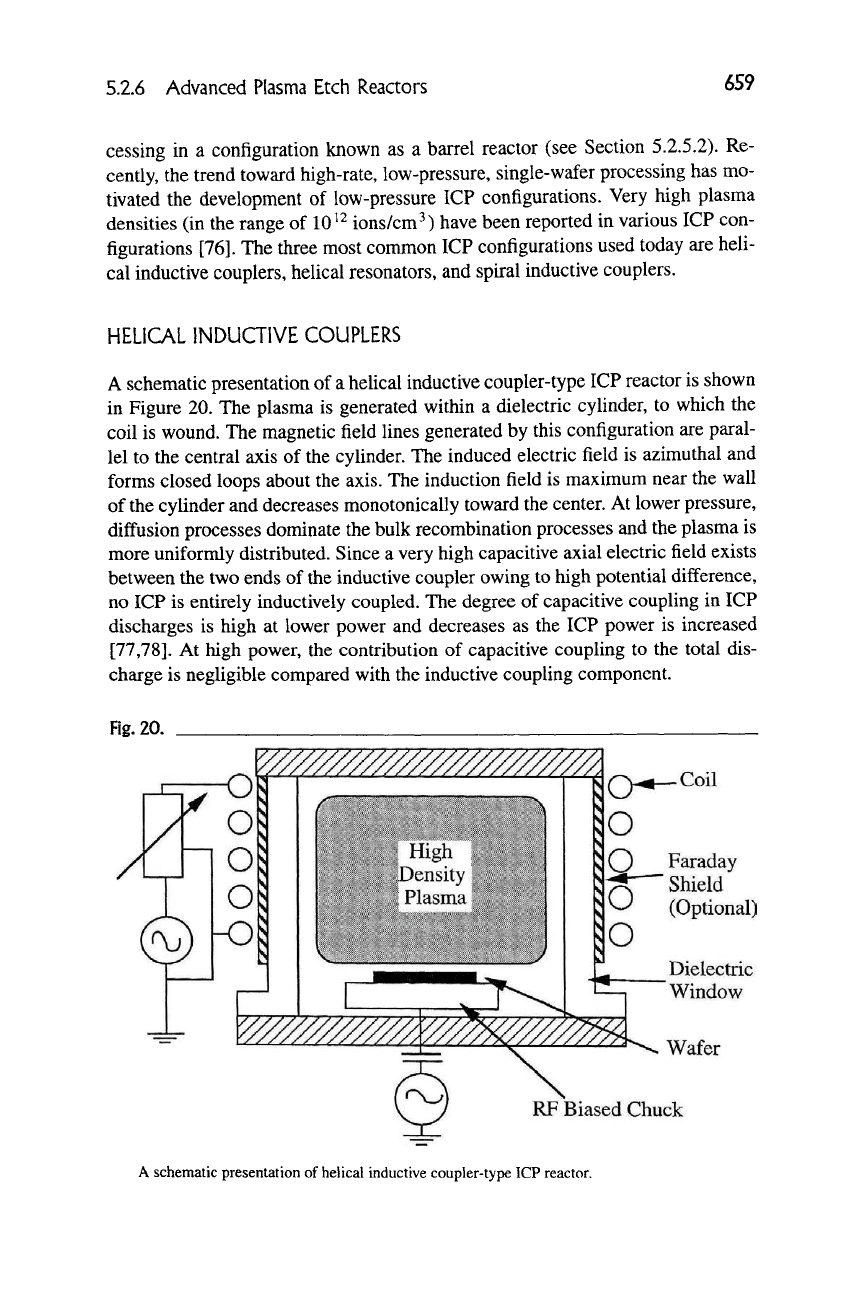
A schematic presentation of a helical inductive coupler-type ICP reactor is shown
in Figure 20. The plasma is generated within a dielectric cylinder, to which the
coil is wound. The magnetic field lines generated by this configuration are paral-
lel to the central axis of the cylinder. The induced electric field is azimuthal and
forms closed loops about the axis. The induction field is maximum near the wall
of the cylinder and decreases monotonically toward the center. At lower pressure,
diffusion processes dominate the bulk recombination processes and the plasma is
more uniformly distributed. Since a very high capacitive axial electric field exists
between the two ends of the inductive coupler owing to high potential difference,
no ICP is entirely inductively coupled. The degree of capacitive coupling in ICP
discharges is high at lower power and decreases as the ICP power is increased
[77,78].
At high power, the contribution of capacitive coupling to the total dis-
charge is negligible compared with the inductive coupling component.
Fig.
20.
O Faraday
^^ Shield
^ (Optional)
Dielectric
Window
Wafer
RF Biased Chuck
A schematic presentation of helical inductive coupler-type ICP reactor.
660
Chapter 5.2: Plasma Etching
In many ICP configurations, a conducting Faraday shield is placed around the
chamber to short out the axial electric field [79]. Note that the design of the shield
should be such that it does not prevent the coupling of induced electric field to the
discharge.
One of
the
earliest applications of this type of configuration in plasma process-
ing was the barrel reactor. In barrel reactors, the wafers are loaded in the center of
the cylinder. This is not an optimized configuration, because the wafers and wafer
holder can significantly disturb the induction fields.
For this type of configuration designed for the low-pressure applications, the
wafers are normally placed in a remote downstream chamber on a chuck with an
independent RF
bias.
This configuration relies on the diffusion of the plasma gen-
erated by the ICP source.
HELICAL RESONATORS
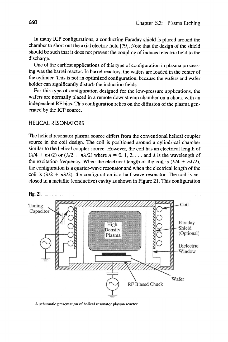
The helical resonator plasma source differs from the conventional helical coupler
source in the coil design. The coil is positioned around a cylindrical chamber
similar to the helical coupler source. However, the coil has an electrical length of
(A/4 -f nkll) or (A/2 + n\l2) where n = 0, 1, 2, ... and
A
is the wavelength of
the excitation frequency. When the electrical length of the coil is (A/4 + nA/2),
the configuration is a quarter-wave resonator and when the electrical length of the
coil is (A/2 + nA/2), the configuration is a half-wave resonator. The coil is en-
closed in a metallic (conductive) cavity as shown in Figure
21.
This configuration
Fig. 21.
Tuning
Capacitor
w^///////y/////////y//////m
r
w/////A/m
O
-O
ro
m?m
o
o
o
w//////////^^^
-Coil
Faraday
-Shield
(Optional)
Dielectric
-Window
Wafer
RF Biased Chuck
A schematic presentation of helical resonator plasma reactor.
5.2.6 Advanced Plasma Etch Reactors
661
provides a parasitic capacitance from the coil to the ground. Because the plasma
conditions can affect the resonance condition of the coil, a tunable capacitor is
normally added between the coil and ground to maintain resonance.
SPIRAL INDUCTIVE COUPLERS
In plasma processing, it is very desirable to generate uniform, dense plasma over
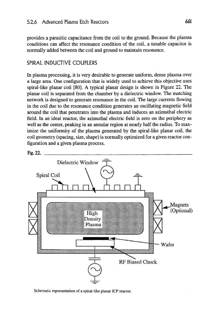
a large area. One configuration that is widely used to achieve this objective uses
spiral-like planar coil [80]. A typical planar design is shown in Figure 22. The
planar coil is separated from the chamber by a dielectric window. The matching
network is designed to generate resonance in the coil. The large currents flowing
in the coil due to the resonance condition generates an oscillating magnetic field
around the coil that penetrates into the plasma and induces an azimuthal electric
field. In an ideal reactor, the azimuthal electric field is zero on the periphery as
well as the center, peaking in an annular region at nearly half the radius. To max-
imize the uniformity of the plasma generated by the spiral-like planar coil, the
coil geometry (spacing, size, shape) is normally optimized for a given reactor con-
figuration and a given plasma process.
Fig.
22.
Dielectric Window
Spiral Coil
nh n n
^^^^^^^^^^^^^^^^J
[^Magnets
(Optional)
Wafer
RF Biased Chuck
Schematic representation of
a
spiral-like planar ICP reactor.
662 Chapter 5.2: Plasma Etching
Since the skin depth of a 13.56 mHz RF induction field is approximately 1-
2 cm in plasmas with electron densities in the order of 10^^ ions/cm\ the sub-
strate may be placed in a close proximity to the inductive coil. Typically, the coil
is separated from the plasma by a 1- to 3-cm-thick dielectric window and the sub-
strate is positioned 5-10 cm below the window. The induced electric field, and
hence the ion generation rate, decay exponentially with the distance, and nor-
mally a tradeoff is made on wafer-positioning distance between maintaining high
plasma density near the substrate and allowing enough diffusion distance for
plasma uniformity.
MATCHING NETWORK FOR ICP SOURCES
The matching network for inductively coupled sources should be able to create a
resonance condition forcing large current to flow through the coil. At the same
time,
the design should not allow generation of very high voltages at nodal points.
It should also be capable of easily igniting the plasma and should have a wide
match window for a large range of
parameters.
The matching network should also
be able to handle high power, since the plasma density does not saturate with
power in excess of 2-3 kw for ICP sources.
5.2.6.5 Electron Cyclotron Resonance Sources
Electron cyclotron resonance (ECR) plasma sources have received a great deal of
attention due to their ability to produce very intense discharge at very low pres-
sures.
ECR sources use microwave excitation schemes (predominantly 2.45 mHz
excitation) to produce low-pressure plasma. ECR sources are characterized by
very low pressure of operation (0.1 mtorr to 10 mtorr). In various ECR schemes,
the microwave power is generated remotely and is coupled to the etch chamber
through a waveguide and a dielectric window. A magnetic field of proper magni-
tude is applied around the chamber to create a resonance condition. The micro-
wave field oscillates in resonance with the electron cyclotron motion about the
magnetic fields. The power absorption is localized to the resonance zone. There
are two commonly used ECR configurations: plasma disk source and diffusion
source.
PLASMA DISK SOURCE
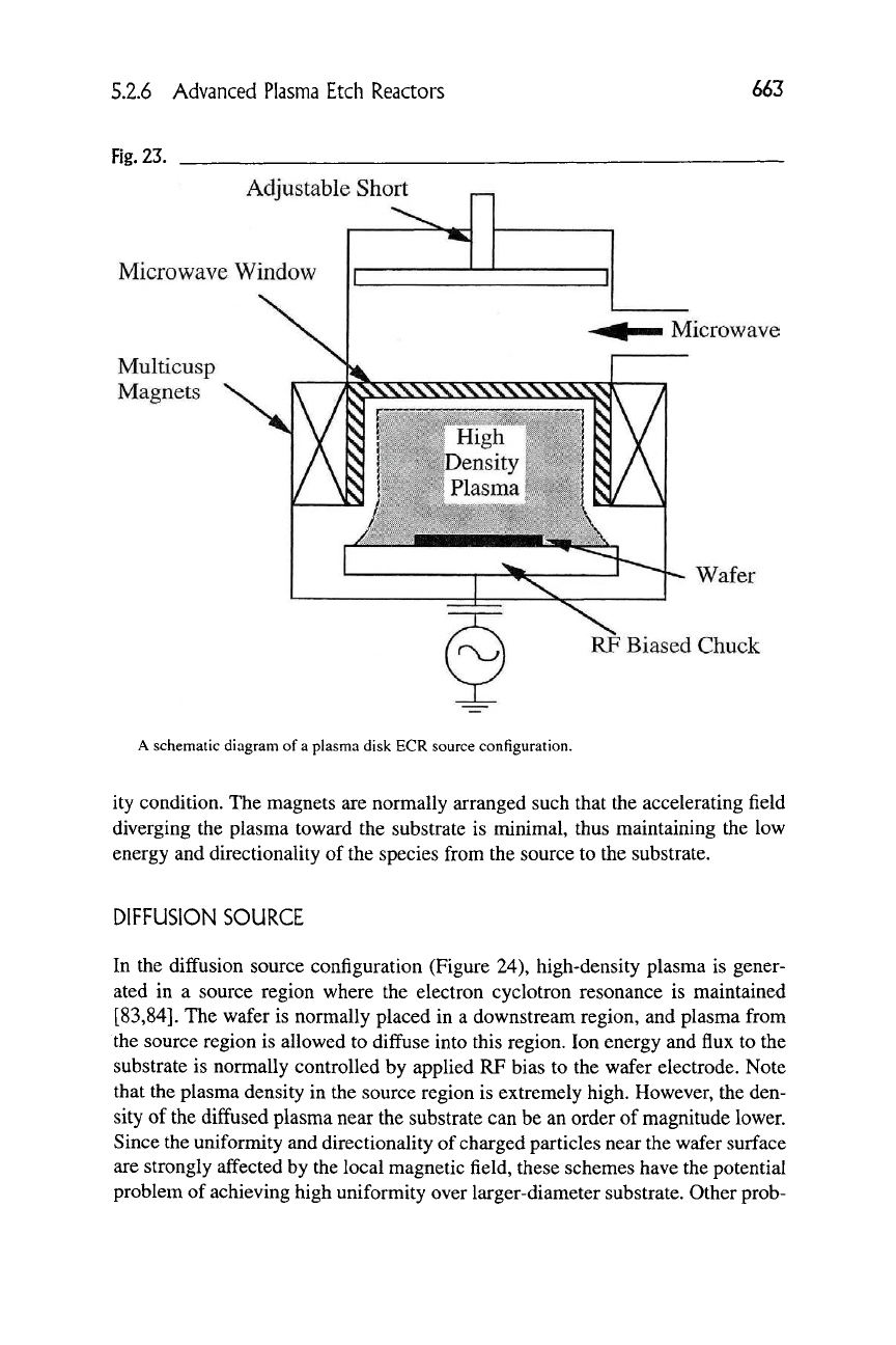
In the plasma disk source approach (Figure 23), the microwaves are directly
coupled and tuned into the plasma chamber via internal adjustments and confined
by a set of electromagnets or permanent magnets in a multicusp array [81,82].
The source is then tuned internally via a sliding short to produce a resonance cav-
5.2.6 Advanced Plasma Etch Reactors
663
Fig.
23.
Adjustable Short
Microwave Window
Multicusp
Magnets
Microwave
N\\\\\\\\\\\\\\NN
r—T
^ r—. r,
1
lo
j;v;v^;'%
High
;:_^,
:^
»^
"^>^'^^;?;Density; V^'^^r^;
/^^\^^ Plasma
^'Vi%^
Wafer
RF Biased Chuck
A schematic diagram
of
a plasma disk ECR source configuration.
ity condition.
The
magnets
are
normally arranged such that the accelerating field
diverging
the
plasma toward
the
substrate
is
minimal, thus maintaining
the low
energy
and
directionality
of
the species from the source
to the
substrate.
DIFFUSION SOURCE
In
the
diffusion source configuration (Figure
24),
high-density plasma
is
gener-
ated
in a
source region where
the
electron cyclotron resonance
is
maintained
[83,84].
The
wafer
is
normally placed
in a
downstream region,
and
plasma from
the source region
is
allowed
to
diffuse into this region.
Ion
energy
and
flux
to the
substrate
is
normally controlled
by
applied
RP
bias
to the
wafer electrode. Note
that the plasma density
in the
source region
is
extremely high. However,
the
den-
sity
of
the diffused plasma near the substrate can
be an
order
of
magnitude lower.
Since the uniformity and directionality
of
charged particles near the wafer surface
are strongly affected by the local magnetic field, these schemes have the potential
problem
of
achieving high uniformity over larger-diameter substrate. Other prob-
