Hoffman D.M., Singh B., Thomas J.H. (Eds). Handbook of Vacuum Science and Technology
Подождите немного. Документ загружается.


644
Fig.
7.
Chapter 5.2: Plasma Etching
Development
of
an Etch tool
Etch tool Design
Parameters
Plasma
Parameters
Etch tool Control
Parameters
' Plasma source
•
Uniformity
of
plasma
•
Gas flow pattern
•
Residence time (pumping)
»Electrode spacing
•
Wall material selection
•
Matching network
• Power supply
Manufacturing
Requirements
Etch
Parameters
' Electron Temperature
•
Ion Temperature
• Plasma density
•
Neutral density
• Sheath potential
' Power
• Pressure
•Flow
• Substrate temperature
• Bias
• Feed gas mixture
»End-point control
Interactive parametric considerations for an etch tool.
• Low Cost
of
Ownership
• High Throughput
• Automation
• Up time/ reliability
• Reproducibility
• Ease
of
process development
• Scaling to larger wafer sizes
• Degree
of
anisotropy
• High rate
• Selectivity
• Etch rate uniformity
• Low particulate
• Low damage
tion. A reactor configuration designed for production is required to meet all these
manufacturing demands.
Production etching systems can have
a
variety
of
configurations depending
on
the parameters of
a
process that must be controlled as well as on the specific appli-
cations of the system. The configurations can vary in terms of excitation frequency
(from few kHz to few gigahertz), operating pressure, and electrode arrangements
(internal, external, capacitive, inductive),
as
well
as
spacing and plasma confine-
ment schemes (magnetic or nomnagnetic).
5.2.5.2 Barrel Reactors
The most basic type
of
reactor
is a
barrel reactor.
It is
characterized
by a
high
operating pressure (>1 torr) and the placement
of
wafers
in the
glow discharge
(usually
on a
quartz holder). This type
of
reactor
is
designed
to
etch
a
batch
of
wafers (multiple wafers) simultaneously. The RF power is normally applied to the
reactor via internal or external capacitive or inductive coupling. Various configu-
rations
of
the barrel reactor are illustrated
in
Figure
8.
This type
of
reactor was
mainly used
for
plasma ashing
of
resist and was very widely used
in
the 1970s.
The major limitation of
this
type of reactor operating at high pressure without any

5.2.5 Basic Plasma Etch Reactors
645
Fig.
8.
Inductive, External
Wafers
Plasma
(a)
Capacitive, Internal
Wafers
Plasma
(b)
Capacitive, External
Wafers
Plasma
(c)
Basic barrel etch reactor configurations.
applied bias on the wafers was dimensional control. Most of the barrel reactors
produce isotropic etch profiles, and their use became limited with shrinkage of
the integrated-circuit dimensions.
5.2.5J
High-Pressure Diodes
Another type of very popular reactor configuration is known as high-pressure pla-
nar diodes, parallel-plate diodes or Reinburg reactors [48]. These reactors are
characterized by fairly high operating pressure (300 mtorr to 10 torr). The wafers
were placed on the grounded electrode, and the RF power was capacitively cou-

646
Fig.
9.
Chapter 5.2: Plasma Etching
Wafers
Schematic diagram of a high-pressure diode system.
pled to the other plate of the diode via a matching network. Often the gas flow is
through the center of the grounded electrode, to produce a uniform flow pattern.
Majority of these configurations were still designed for batch etching. They can
produce both directional and anisotropic etch profiles. The schematic diagram of
the reactor is shown in Figure 9.
5.2.5.4 Low-Pressure Diodes or Reactive Ion Etchers
In the next generation of plasma etching machines, the role of electrodes was re-
versed. The wafers were placed on the electrode to which the RF power was ap-
plied. These type of systems were known as low-pressure diodes or reactive ion
etching (RIE) reactors. The name "reactive ion etching" became very popular de-
spite the fact that the contribution of ions in the chemical etching reaction was
negligible. This configuration is characterized by low operating pressure (30 mtorr
to 300 mtorr). Low-pressure diode configurations were widely used for etching
applications because of their simplicity and ability to direct energetic ions normal
to the surface being etched. The etching in this type of reactor is almost always in-
herently directional. This type of configuration is the most studied configuration
to date and was widely used in production till the late 1980s. In one of the com-
5.2.5 Basic Plasma Etch Reactors
647
Fig.
10.
Wafers
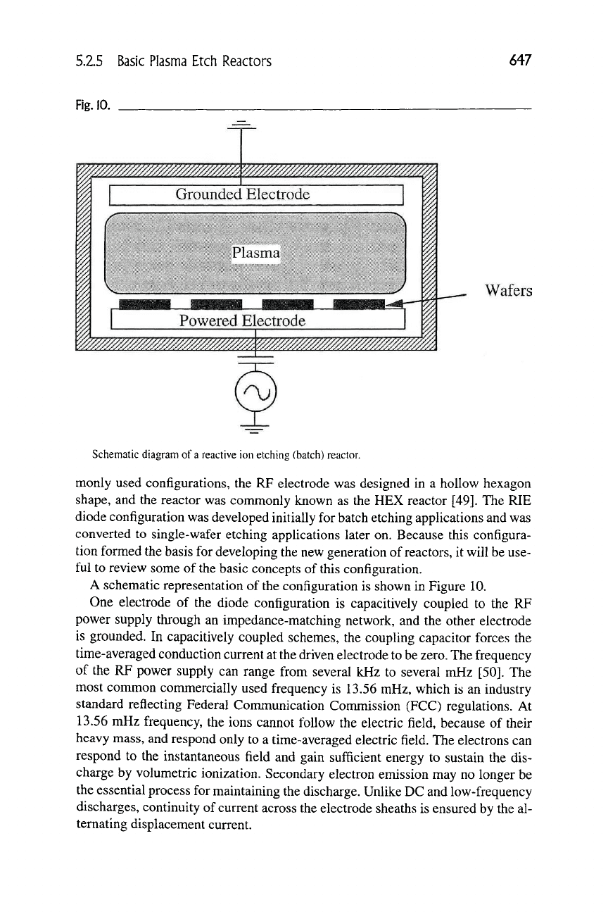
Schematic diagram of a reactive ion etching (batch) reactor.
monly used configurations, the RF electrode was designed in a hollow hexagon
shape, and the reactor was commonly known as the HEX reactor [49]. The RIE
diode configuration was developed initially for batch etching applications and was
converted to single-wafer etching applications later on. Because this configura-
tion formed the basis for developing the new generation of
reactors,
it will be use-
ful to review some of the basic concepts of this configuration.
A schematic representation of the configuration is shown in Figure 10.
One electrode of the diode configuration is capacitively coupled to the RF
power supply through an impedance-matching network, and the other electrode
is grounded. In capacitively coupled schemes, the coupling capacitor forces the
time-averaged conduction current at the driven electrode to be
zero.
The frequency
of the RF power supply can range from several kHz to several niHz [50]. The
most common commercially used frequency is 13.56 mHz, which is an industry
standard reflecting Federal Communication Commission (FCC) regulations. At
13.56 mHz frequency, the ions cannot follow the electric field, because of their
heavy mass, and respond only to a time-averaged electric field. The electrons can
respond to the instantaneous field and gain sufficient energy to sustain the dis-
charge by volumetric ionization. Secondary electron emission may no longer be
the essential process for maintaining the discharge. Unlike DC and low-frequency
discharges, continuity of current across the electrode sheaths is ensured by the al-
ternating displacement current.

648
Chapter S.2: Plasma Etching
MATCHING NETWORK
Majority of the RF power generators are designed to drive a purely resistive
load of 50 ohms. The RF discharge normally has a capacitive component due to
sheaths. To match the discharge impedance with the output of the generator for
coupling maximum power to the discharge, a matching network is placed very
close to the discharge. A typical matching network configuration is shown in Fig-
ure
11.
The reactive components of the network are tunable and are adjusted until
the impedance of the matching network is matched to the plasma impedance to
give a 50-ohm termination for the power generator. In this case, the reflected
power goes to zero. Normally, the current, voltage, and phase are sensed by sens-
ing elements and feed back to tuning elements for autotuning the network to
match the plasma load. The autotuning must be achieved in only a few seconds,
because the total time to etch can be less than a minute.
INDUCED
DC
BIAS
In capacitively coupled RF discharges, the time-averaged conduction current to
the powered electrode must be zero, and this requirement is accomplished by for-
mation of a self-induced DC potential. The formation of the induced DC bias,
V^^,
on the RF electrode can be explained as follows. Total conduction current
(of the electrons and ions) to the electrode wall must be zero. However, in an RF
sheath, this conduction is applicable only on a time-averaged basis, i.e., averaged
over a cycle. Due to the smaller mass of
electrons,
the electron current to the elec-
trode is much larger than the ion current during an RF cycle if there is no DC bias
to the electrode. A negative DC bias is self-induced on the electrode to balance
the electron and positive ion current averaged over an RF cycle. The potential
drop in the sheath on a time-averaged basis is the difference between the time-
averaged plasma potential and the self-induced DC bias on the electrode. The
large potential drop in the sheath accelerates ions toward the electrode and de-
creases the electron current to the electrode. Because of their mass, ions respond
Fig.
11.
RF Supply
r
L
^
"mm^
(?rvPlasma r)
Matching network
A typical RF matching network.
5.2.6 Advanced Plasma Etch Reactors
649
only to the time-averaged sheath field and flow to the electrode at nearly a steady
rate.
On the other hand, for most of the cycle the wall potential is strongly nega-
tive with respect to plasma, because of the self-induced bias, the electrons are re-
pelled from the wall, and negligible current flows to the wall. Only near the peak
of the RF cycle, when the RF electrode is the most positive, the sheath for elec-
trons become thin and its potential drop is small, which allows a short burst of
electrons to reach the wall. The negative charge carried by this short burst of elec-
trons equals the positive charge of ions flowing to the wall continuously through-
out the cycle.
In plasma processing, the DC bias (K/^) is normally used as an energy indicator
for ions impinging on the powered electrode. The value of the induced bias de-
pends on the power, pressure, nature of
gas,
area ratio of electrodes, and electrode
surface conditions. In most commercial plasma reactors, V^/^ is measured at a
point as close as possible to the electrode via a chock coil (for attenuating RF
voltage) and a low-pass filter.
LIMITATION OF THE DIODE CONFIGURATION
The major limitation of the diode configuration is the strong coupling between
the plasma generation and the induced bias. It is very difficult to optimize all the
etching characteristics simultaneously using conventional parallel-plate etch-tool
configurations. To increase etch rate, for instance, the gas density (pressure) can
be raised; but, this may reduce the average ion energy and directionality at the
wafer owing to collisions in the sheath and can negatively impact the anisotropy.
The other major limitation of the diode configuration is the operating pressure
range. Generally, the performance of parallel-plate diode configuration degrades
at lower pressures, that
is,
below operating pressures of
30
mtorr
[51].
The plasma
density drops to unacceptable levels as observed by very low etch rates, and the
induced bias on the electrodes rises to unacceptable levels, enhancing the possi-
bility of wafer damage and contamination.
5.2.6
ADVANCED PLASMA ETCH REACTORS
5.2.6.1 Basic Requirements for Advanced Plasma Etch Reactors
The major limitation of the batch etching machines were wafers-to-wafer and
batch-to-batch uniformity and reproducibility. To achieve better control and re-
producibility of the etch process, the newer reactors were designed to etch only
one wafer at a time. They are commonly known as single-wafer etchers (SWE).
The need for single-wafer etching has forced the industry to develop many new
650 Chapter 5.2: Plasma Etching
SWE configurations capable of high-rate etching. Another desirable feature of a
plasma etching tool is its ability to independently control many of the etching char-
acteristics. In addition, it should possess, if
possible,
the simplicity of
the
parallel-
plate configurations and should be easily adaptable to the existing production
lines.
Beside high-rate etching, uniformity, and reproducibility, the development
of the advanced reactor configurations has been driven by the following two re-
quirements: (1) low-pressure operation, and (2) independent control of bias from
plasma generation.
NEED FOR LOW-PRESSURE ETCHING
The stringent requirements of anisotropy for submicron circuit fabrication de-
mand that the etching is performed at lower pressures (<100 mtorr). This is due
to the fact that the scattering in ion directionality and energy in the sheath region
is minimized, and better anisotropy is achieved, as the mean free path is increased
at lower pressure. Due to inherent anisotropy at lower pressure, cleaner chemistry
can be used, thus reducing the effects of chemistry-induced contamination [52].
Similarly, at lower pressure, etch reaction by-products are more volatile, and the
microloading or aspect ratio dependent etch (ARDE) nonuniformity is greatly
reduced.
The linear decrease in gas density with pressure requires that the ionization and
dissociation efficiency of the reactor must be high to maintain adequate etch rates
at lower pressures. Lower pressure operation also affects the concentration of neg-
ative ions in the discharge. Generally, the relative concentration of negative ions
in the plasma is decreased due to reduced attachment cross sections at low pres-
sure
[53].
The overall kinetic behavior of low-pressure plasma differs significantly
from that at higher pressure.
LOW-PRESSURE OPERATION BY MAGNETIC ENHANCEMENT
To extend the operation of an etch tool to very low pressures (<10 mtorr), some
form of magnetic enhancement can be devised. Typically, magnetic fields are
used to increase the collision probability between electrons and neutral feed gas
molecules and thereby generating dense, stable plasma at lower pressures.
When a magnetic field is applied, the electrons are trapped in magnetic field
lines and gyrate around it. This radius is smaller where magnetic field density is
higher. Electrons also travel along the magnetic field line, and the resultant path is
helical. Because of the negative potential of the walls and electrodes with respect
to the plasma potential and gradient in the magnetic field, the electrons are re-
flected back and forth between points where the lines enter and leave the wall sur-
face (referred as the "mirror effect") [54]. Electrons experience drift due to
Lorentzian forces. Electrons
also
jump from one magnetic field line to the next as

5.2.6 Advanced Plasma Etch Reactors
651
they collide with the neutral gas molecules. At higher pressures, these kinds of
collisions dominate and magnetic field have little or no effect on electron confine-
ment. However, at low pressures, the electrons are trapped in the magnetic field,
and their path length and lifetime in the system are thereby greatly increased.
The ions also meet the same forces, but because of their greater mass and slower
speed, their motion is quite different from that of electrons. Because of their greater
mass,
ions have much larger gyration radius than that of electrons, and ions are
poorly confined in magnetic fields.
Using a proper magnetic confinement scheme can enhance ionization and dis-
sociation efficiency of the plasma source at low pressures. There are two popular
magnetic enhancement schemes. In one scheme, magnets are placed to produce
magnetic field parallel to electrodes. In this scheme, it is very difficult to obtain
uniform magnetic field, hence the plasma uniformity is degraded. The other
scheme uses magnets in a multipolar bucket form. The multicusp arrangement is
created by having rows of permanent magnets with alternating polarity. These
multipolar devices are characterized by a relatively field-free region in the center
and a high-intensity periphery field that "shields" the walls. Effectively, the pe-
ripheral multipolar field causes magnetic confinement of
the
plasma electrons and
provides more efficient gas ionization at low pressures. The cusp fields also lead
to much improved plasma homogeneity.
DECOUPLING OF SUBSTRATE BIAS FROM PLASMA GENERATION
To obtain faithful pattern transfer, it is desirable to operate reactors at low pres-
sures to minimize, for example, scattering of ions while producing a dense uni-
form plasma to maximize etch rates [55,56,57]. An ideal plasma etch reactor
should allow independent control of the substrate bias from plasma generation.
In this case, the plasma generation (density, uniformity) and the substrate bias,
which can cause damage, can be optimized separately. This concept is illustrated
in Figure 12.
Fig.
12.
Magnetic
Confinement
(optional)
X0
Substrate
High density plasma generation
Plasma transport
Uniform plasma
Field free plasma near substrate
Ion acceleration (bias control)
Concept of
decoupling
substrate bias from plasma generation.
652 Chapter 5.2: Plasma Etching
In new reactor designs, this objective is achieved by using two powered elec-
trodes. One electrode, on which the wafers rest is normally biased with a capaci-
tively coupled RP power supply. The other electrode functions as the source for
plasma generation. This electrode can be powered using various schemes such as
capacitive, inductive, or electron cyclotron resonance excitation. Various mag-
netic schemes can also be applied for confining and optimizing the plasma prop-
erties at lower pressures.
5.2.6.2 Magnetically Enhanced Diode
One of the most common approaches for magnetic enhancement is the magne-
tron. Magnetron sources are widely used in sputtering, and a number of publica-
tions outline the geometry of various magnetron schemes [58,59]. A comprehen-
sive review of
this
subject is given by Vossen and Kern [60]. Arrangements similar
to those used for magnetron sputtering have also been widely used for etching ap-
plications. In a magnetron-based etcher, a highly uniform magnetic field and plan-
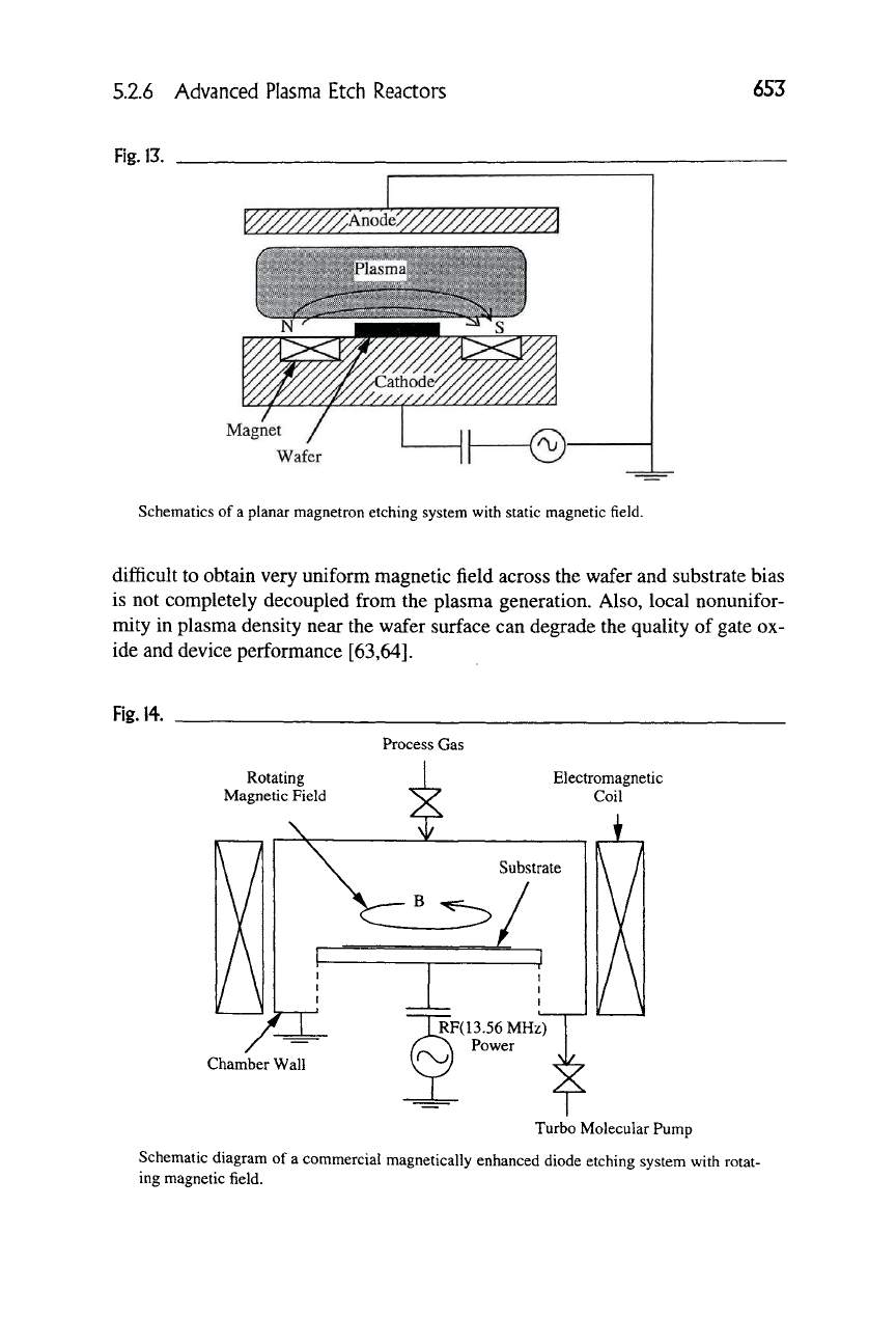
ner electrodes are essential for achieving acceptable etch-uniformity. Figure 13
shows one of the most common magnetron configurations, the planar magnetron,
in which a static magnetic field is applied parallel to the electrode to create an in-
tense plasma zone [61]. This configuration is widely known as the magnetically
enhanced reactive ion etcher (MERIE). A nearly parallel magnetic field is formed
over the hollow region of the magnet where the wafer is normally kept. The elec-
tric field formed by the plasma sheath is perpendicular to the magnetic field, in-
creasing the ionization efficiency near the electrode surface. The magnetic field
reduces the mobility of electrons near the electrode, and the induced bias in a
magnetron is generally much lower than a conventional diode system for similar
operating conditions. However, the configuration shown in Figure
13,
in conunon
with all magnetron-based reactors, suffers from poor plasma uniformity and in-
creased damage at lower pressures. To improve magnetic field uniformity, several
dynamic magnetron apparatuses have also been used in commercial systems.
Figure 14 shows one of the commercially available configurations in which
electromagnets are used to rotate the magnetic field at 0.5 Hz parallel to the elec-
trode surface. The magnetic field intensity can be adjusted depending on the ap-
plication. The advantage of
a
rotating magnetic field is that it reduces the problem
of nonuniform intensification of plasma associated with the static field configura-
tion. In another scheme, permanent magnets arranged in a racetracklike belt are
mechanically scanned over the wafer surface [62].
In general, magnetron schemes result in higher etch rate and lower induced
bias and can be operated at much lower pressures. Improvement in ionization
efficiency and etch rate generally depends on the applied magnetic field intensity.
However, magnetron schemes generally suffer from the fact that it is extremely
52.6 Advanced Plasma Etch Reactors
653
Fig.
13.
Magnet
Wafer
Schematics of
a
planar magnetron etching system with static magnetic field.
difficult to obtain very uniform magnetic field across the wafer and substrate bias
is not completely decoupled from the plasma generation. Also, local nonunifor-
mity in plasma density near the wafer surface can degrade the quality of gate ox-
ide and device performance [63,64].
Fig.
14.
Process Gas
Rotating
Magnetic Field
/^
Electromagnetic
Coil
Chamber Wall
JlF(13.56MHz)
I
^ 1 Power
Turbo Molecular Pump
Schematic diagram of a commercial magnetically enhanced diode etching system with rotat-
ing magnetic field.
