Ghodssi R., Lin P., MEMS Materials and Processes Handbook
Подождите немного. Документ загружается.

674 D.R. Hines et al.
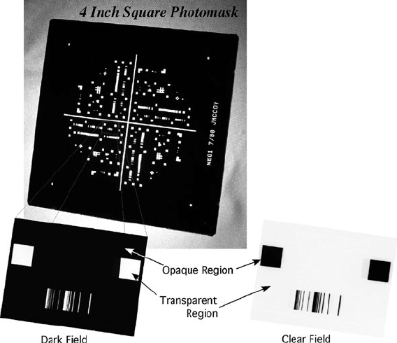
Fig. 9.4 Optical images of 4 in.
2
square photomask. Magnified area represented in both clear field
and dark field
lithography schemes where this is necessary. Photomasks can be designed for either
clear field or dark field patterning as s hown in the lower panels of Fig. 9.4. A dark
field mask has the desired pattern contained in the transparent part of the mask
whereas the clear field mask has the pattern contained in the opaque part of the
mask.
For contact, soft-contact, and proximity lithography the mask is designed to pro-
duce a 1:1 image in the photoresist layer [26]. These masks come in contact or close
contact (10–20 µm above the photoresist surface) with the photoresist layer and thus
are susceptible to contamination and wear. A contact mask may need to be cleaned
on a regular basis which exposes the surface to additional damage. Contact masks
are mostly used for research and development and prototyping. For low-resolution
processing, an inexpensive transparency mask can be made using a drawing program
on the computer and a printer loaded with transparency film. Photomasks with res-
olution in the 30–40 µm range can be made using a professional graphics (>3000
dpi) quality printer. Standard laser printers (<1200 dpi) can achieve a reasonable
resolution but cannot typically achieve the necessary level of opacity to print usable
masks.
Projection lithography masks (often called reticles) are typically designed to pro-
duce 1:4, 1:5, or 1:10 reduced images in the photoresist layer. They are used with
9 MEMS Lithography and Micromachining Techniques 675
an optical projection system where the image of the mask is projected onto the sur-
face of the photoresist layer through a complex series of optics. Because projection
masks do not come into contact with the photoresist layer, they are much less sus-
ceptible to wear or damage and therefore are more suitable for use in high-volume
production facilities.
There are four variations of projection photomasks. The simplest type uses a
combination of transparent and opaque regions to define a pattern that can be
imaged onto a photoresist layer. The resolution of such a standard projection mask is
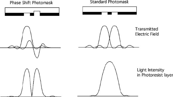
diffraction-limited [27]. To overcome diffraction limitations by very closely spaced
features, optical interference effects can be engineered into the mask. This can be
accomplished by either changing the thickness of a transparent region of the mask
(alternating phase-shift) [28] or by increasing the transmittance of the originally
opaque region of the mask (attenuated phase-shift) [29]. Such phase-shift modifi-
cations in the transmitted light through a photomask cause either constructive or
destructive interference patterns. With proper mask engineering of features on the
photomask, the resulting light intensity pattern imaged into the photoresist layer
can be of higher resolution than was achievable with a standard photomask as is
illustrated in Fig. 9.5.
Fig. 9.5 Transmitted light intensity through (left panel) a phase shift photomask as compared to
that for (right panel) a standard photomask (Modified from [30])
A standard projection photomask can be further modified by pixelating an orig-
inally opaque region of the mask. If the pixel size and spacing are below the
resolution limit of the optical projection system then the pixelated region attenu-
ates the intensity of the transmitted light without imaging individual pixels into the
photoresist. These styles of masks are used for grayscale lithography. Due to mask
fabrication limits and resolution limits of a given optical projection system, a finite
number of discrete pixel sizes and spacings can be realized. Each discrete pixel size
and spacing translates into a specific intensity of transmitted light from 100% (trans-
parent region, no pixels) to 0% (opaque region). Each intensity level is referred to as

676 D.R. Hines et al.
Fig. 9.6 Cross-section
illustration of (a) standard
projection photomask, (b)
alternating phase-shift
photomask, (c) attenuated
phase-shift photomask, and
(d) grayscale photomask
a gray-level. An illustration of the different types of projection photomasks is shown
in Fig. 9.6.
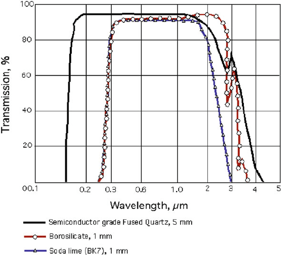
Photomasks are typically made from soda-lime glass, borosilicate glass, or fused
quartz. Thermal expansion and optical transmission are the primary considerations
for choosing the mask material. Table 9.1 lists the thermal expansion coefficients for
these materials. The transmission properties are shown in Fig. 9.7. The dimensions
of soda-lime glass can change by 1.2 µm across a 5 in. mask for every 1
◦
C change
in temperature. However, for mask fabrication tools and steppers that are housed in
a temperature-controlled environment, this is not typically a great concern and thus
soda-lime glass can be used. For mask fabrication tools that use e-beam lithography,
the mask is in a high vacuum environment, which can affect heat transfer. Therefore,
borosilicate glass is more commonly used with these e-beam mask-writing tools.
In UV lithography applications using wavelengths shorter than 350 nm, and for
applications achieving very high resolution, quartz masks are needed due to thermal
effects and transmissivity.
Table 9.1 Thermal
coefficient for materials used
as photomasks
Material Thermal coefficient, ppm/
◦
C
Soda lime 9.3
Borosilicate 3.7
Quartz 0.5
Reproduced with permission from [31],
Microlithography: From Computer Aided Design
(CAD) to Pattern Substrate, Cornell NanoScale Science
and Technology Facility
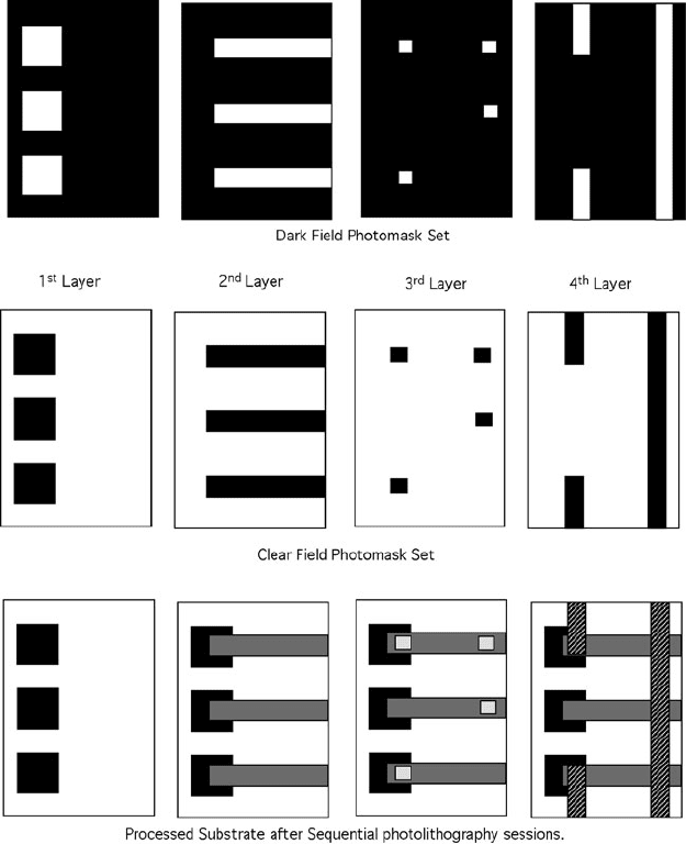
Typically, electronic circuits and completed MEMS devices are fabricated in
stages, requiring several sequential photolithography steps. Each step or layer
requires a separate photomask containing part of the overall circuit or device pattern
that must be carefully aligned to the previously patterned features on the substrate.
An example of a four-layer photolithography process and the associated photomasks
(both clear and dark field mask sets) are shown in Fig. 9.8.
9 MEMS Lithography and Micromachining Techniques 677
Fig. 9.7 Transmission of UV light through different mask materials (Modified from [30])
9.2.2 Optical Projection Systems
Optical projection systems are the tools used to create an image of the pattern con-
tained in the photomask onto the surface of the photoresist layer. They typically
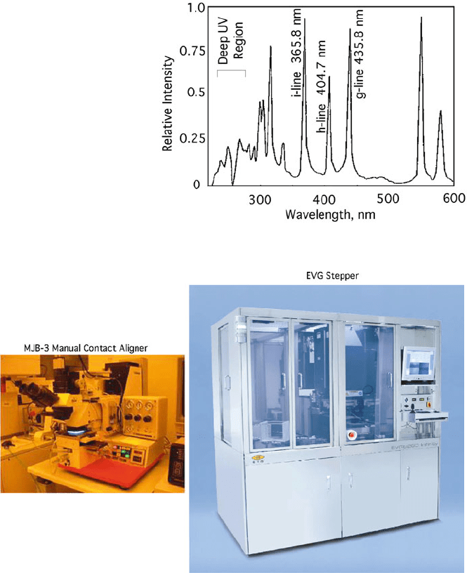
utilize UV light from a mercury arc lamp the spectral emission of which is shown
in Fig. 9.9. Several prominent emission lines are visible in the UV region of the
spectrum at 435.8, 404.7, and 365.4 nm which are referred to as g-, h-, and i-lines,
respectively. Both optical projection systems and photoresist formulations have been
optimized for maximum performance at these wavelengths.
9.2.2.1 Contact Aligner
A contact aligner (used with contact and proximity masks) consists of a UV light
source for exposure, a microscope with X, Y, Z and rotation (R) stages for wafer
alignment and a mask holder. The mask and a photoresist covered wafer are brought
into close proximity with the Z stage and aligned as needed with the X, Y, and R
stages. Once aligned, the wafer and mask are brought into full contact (or close
proximity) and exposed. Contact aligners are typically benchtop units, of which the
MJB3 (shown in Fig. 9.10) and the MA-6 are commonly used examples. A con-
tact aligner transmits a 1:1 image of the photomask onto the photoresist layer. This
678 D.R. Hines et al.
Fig. 9.8 Multilevel mask set for sequential photolithographic fabrication. Mask set examples are
shown for both (a) bright field (clear field) and (b) dark field masks. The final patterned substrate is
illustrated in (c)[25] (Modified from http://www.photronics.com/about/basics.jsp Reprinted with
permission of PHOTORONICS, INC. from Photomask Basics)
allows large area patterns to be exposed into the photoresist in one step. Because
the photomask and photoresist layer are in direct contact, there are no focusing
problems onto the surface of the wafer. Substrates of various thicknesses can be
easily handled and the alignment/exposure is not sensitive to wedge error (substrate
not perfectly flat in relation to the projected image) as the substrate holder can tilt
slightly to provide intimate contact with the mask.
9 MEMS Lithography and Micromachining Techniques 679
Fig. 9.9 Hg emission versus
wavelength (Reprinted with
permission from [32])
Fig. 9.10 Optical lithography systems: Manual contact aligner (left) and stepper (right) (Aligner
reprinted courtesy of SUSS MicroTec Lithography GmbH, stepper reprinted courtesy of EV Group,
Inc.)
Mixing photolithography with other patterning methods is also possible. For
example, nanoimprint lithography features can be etched into the surface of a pho-
tomask allowing simultaneous patterning via both NIL and photolithography. Also,
printing methods can be combined with photolithography by applying a printable
layer or ink to the surface of a photomask. Such combined patterning methods
680 D.R. Hines et al.
require contact to the substrate and therefore are only possible using contact aligner
photomasks.
Contact aligners also possess several disadvantages. Contact between the pho-
tomask and the photoresist layer can cause damage to the photomask and is also
a source of dirt and contamination. Particles trapped between the photomask and
the photoresist layer, or a nonuniform photoresist layer can prevent proper contact
and thus adversely affect the quality of the patterned features in the photoresist.
Resolution is typically less for contact aligners as compared to steppers. Also con-
tact aligners are less automated than steppers resulting in slower and less accurate
operation.
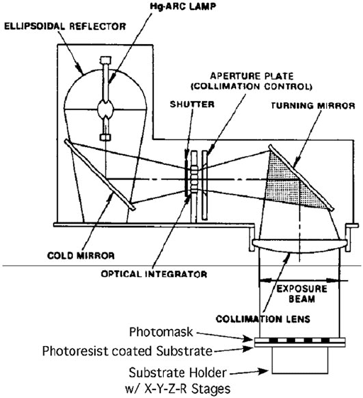
Figure 9.11 contains a diagram showing the main components of a contact
aligner. Some contact aligners have the ability to perform backside alignment. This
allows the bottom surface of a substrate to contain a pattern that is in alignment with
a pattern on the top surface of the same substrate. The aligner uses a second set of
optics to align the previously patterned bottom surface of the substrate to a stored
image of the photomask. Once aligned, a photoresist layer on the top surface of the
substrate can be patterned.
Fig. 9.11 Diagram showing the main components of a contact aligner (Reprinted with permission
from [3])
9 MEMS Lithography and Micromachining Techniques 681
9.2.2.2 Stepper
A stepper (used with projection photomasks or reticles) differs from a contact
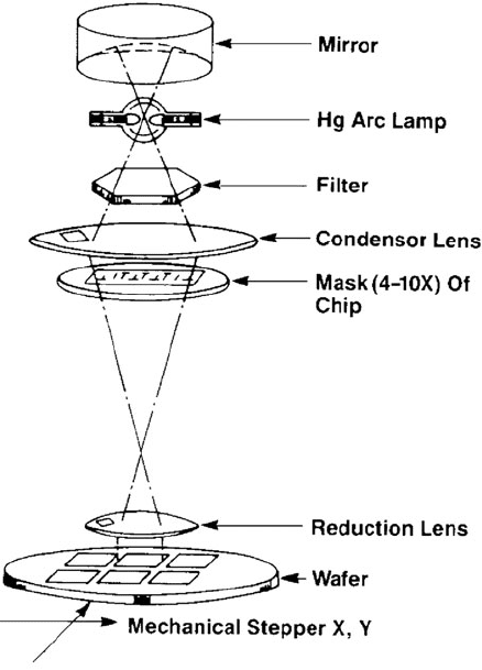
aligner in several ways. Primarily, a stepper contains an optical projection system
that can produce an image of the photomask onto the surface of the photoresist layer.
The image at the photoresist surface is typically a 1:4, 1:5, or 1:10 reduction i n the
size of the mask pattern and covers only a small area on the substrate. The lens sys-
tem in a stepper is complex and contains numerous large-size optical elements, only
a few of which are shown schematically in Fig. 9.12.
Fig. 9.12 Simplified
schematic drawing of optical
components in a stepper
(Reprinted with permission
from [33])
This lens system is designed to correct optical aberrations over a 30 mm circu-
lar field of exposure, therefore, alignment is critical and processes are sensitive to
temperature, humidity, and vibrations. For this reason, the lens assembly is housed
in a massive, vibration isolation enclosure equipped with both precise temperature
and humidity control. The alignment of the photomask to the photoresist-coated
substrate is much more computer controlled for the stepper as compared to the
contact aligner. Also the position of the substrate holder is manipulated by high-
precision, computer-controlled micrometers. As can be seen in Fig. 9.10, a stepper is
682 D.R. Hines et al.
Fig. 9.13 Die layout on
exposed substrate
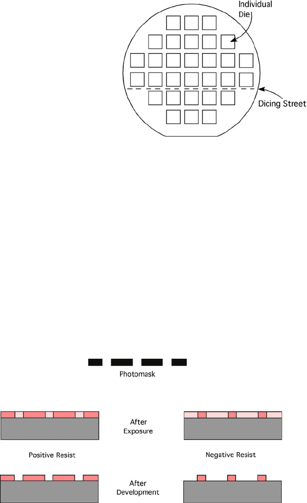
usually a large format machine. The entire substrate is processed by moving (step-
ping) the substrate to an unexposed area and repeating the exposure. Each exposure
of the mask is referred to as a die on the substrate. The stepping/exposing process is
repeated until the entire area of the substrate has been processed in a layout similar
to that illustrated in Fig. 9.13.
9.2.3 Photoresist
Photoresist typically consists of a mixture of organic polymers in a solvent com-
bined with photosensitive additives. Photoresist is designed to change solubility
due to exposure to UV light. The exposed area becomes either more soluble (pos-
itive resist) or less soluble (negative resist) upon exposure. The difference between
these two main types of photoresist chemistries (positive and negative photoresist)
is illustrated in Fig. 9.14.
Fig. 9.14 Patterning of positive and negative photoresist highlighting regions of insolubility that
remain after exposure and developing [32]
9 MEMS Lithography and Micromachining Techniques 683
Photoresist chemistry is designed to have an extremely high contrast; changes in
solubility are nonlinear and exhibit a threshold response resulting in sharply defined
features with steep sidewalls even where small exposure intensity fluctuations exist
within the photoresist layer. An example would be exposing photoresist to a sine
wave intensity pattern. The desired result would be a sawtooth pattern in the pho-
toresist layer rather than a sine wave pattern. In some cases, reflection of light from
the substrate surface can produce interference effects within the photoresist layer.
This is more an issue in situations utilizing steppers that employ higher intensity
light sources as compared to contact aligners.
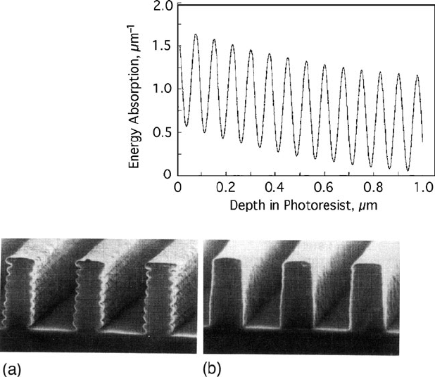
A standing wave profile as a function of photoresist thickness is shown in
Fig. 9.15 which results in a sidewall profile as illustrated in Fig. 9.16. Such side-
wall roughness can be drastically reduced by performing a postexposure bake [34].
Also, antireflective coatings (ARC) are sometimes applied to the substrate surface
prior to the application of the photoresist layer [35].
Due to absorption affects, the top surface of the photoresist receives a larger
exposure dose than the bottom surface. This results in a slightly larger exposed
area at the top surface as compared to the bottom surface. This means that more
Fig. 9.15 Energy absorption
of UV light as a function of
depth in a 1 µm thick layer of
photoresist (Reprinted with
permission from [32])
Fig. 9.16 Example of reflective standing wave effect of photoresist sidewall profile (a) without
and (b) with antireflective coating (Reprinted with permission from B.W. Smith, M. Hanratty:
Multilayer resist Technology, Chapter 10, In J.R. Sheats, B.W. Smith (Eds.): Microlithography
Science and Technology (Marcel Dekker, New York, NY, 1998))
