Ghodssi R., Lin P., MEMS Materials and Processes Handbook
Подождите немного. Документ загружается.

284 R.G. Polcawich and J.S. Pulskamp
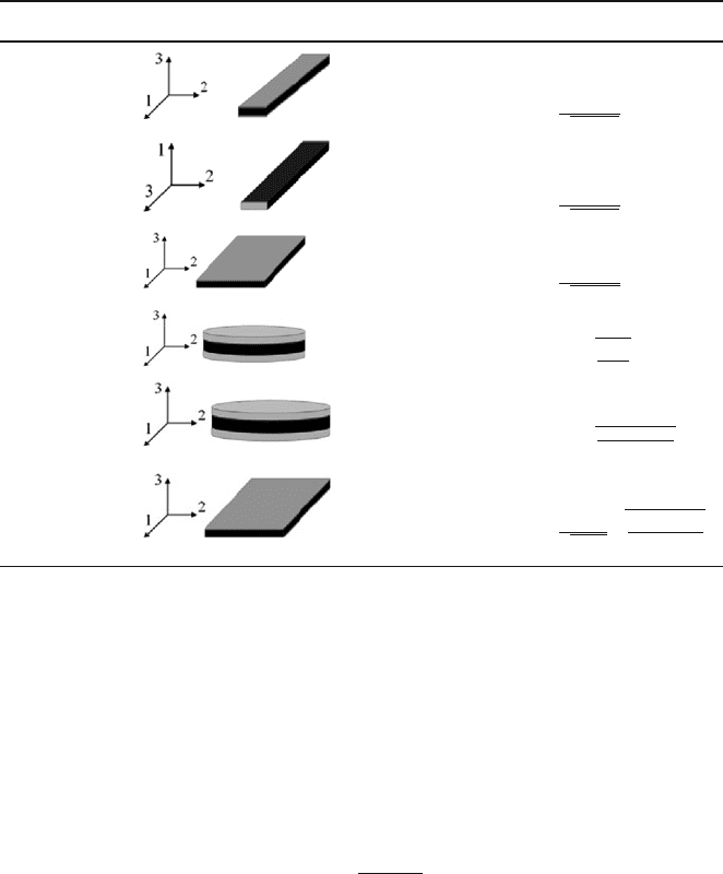
Table 5.1 Definition of the electromechanical coupling coefficients for elements of different
geometries
Coupling factor Resonator geometry Boundary conditions Value
k
31
T
1
,x
1
,x
2
,x
3
nonzero
d
31
s
E
11
ε
o
ε
T
33
k
33
T
3
,x
1
,x
2
,x
3
nonzero
d
33
s
E
33
ε
o
ε
T
33
K
15
T
5
&x
5
nonzero
e
15
c
D
55
ε
o
ε
x
11
k
t
(thickness) x
3
,T
1
,T
2
,T
3
nonzero k
33
ε
0
ε
T
33
c
D
33
k
p
(planar) x
1
,x
2
,x
3
,T
1
,T
2
,
nonzero
k
31
2
1+
(
s
E
12
s
E
11
)
k
31
x
1
,x
3
,T
1
,T
2
, nonzero
k
31
1−k
2
31
1−
(
s
E
12
s
E
11
)
1+
(
s
E
12
s
E
11
)
that defines the strain energy density in Equation ( 5.13). However, under resonant
conditions, the strain field is defined by the relevant vibrational modeshape and is
therefore nonuniform. Thus defining the ratio of stored and input mechanical and
electrical energies requires information regarding the vibrational mode in addition
to the elastic, dielectric, and piezoelectric constants. A common definition of the
effective coupling factor is given by Equation (5.14). This defines the effective cou-
pling factor in terms of the resonance (f
r
) and antiresonance (f
a
) frequencies obtained
from a one-port measurement of the admittance of a piezoelectric resonator.
k
2
eff
=
f
2
a
− f
2
r
f
2
a
(5.14)
5.1.3.3 Influence of Boundary Conditions
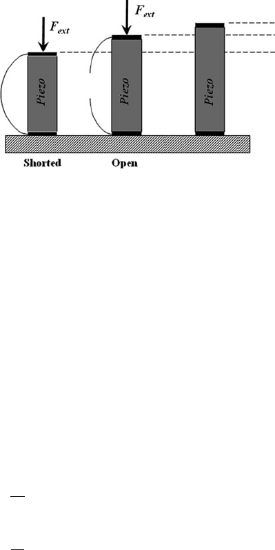
As stated earlier, the electromechanical coupling inherent to piezoelectricity leads
to a dependence of the permittivity and elastic constants on both the electrical and
mechanical boundary conditions. For example, in the case of the direct effect, a
constant external stress is applied to an equal potential electroded piezoelectric as
depicted in Fig. 5.13. The external stress generates piezoelectrically induced charges
5 Additive Processes for Piezoelectric Materials 285
Fig. 5.13 Actuation response
under different electrical
boundary conditions
on the two electrodes. Under short-circuited electrodes, current is allowed to flow
between the electrodes to maintain the equal potentials. Under open-circuit condi-
tions, the charges are constrained to the electrodes and induce an internal electric
field within the piezoelectric material. This field, via the indirect piezoelectric effect,
actuates the material by providing stresses opposed to the externally applied stress.
The material therefore requires a greater external stress for a given deformation
under the open circuit condition and hence appears stiffer. Generally, only a lim-
ited number of the elastic constants will be influenced by the piezoelectric effect.
These modified terms are referred to as piezoelectrically stiffened elastic constants.
The permittivity has a similar response under varied mechanical boundary con-
ditions. The ratio between the mechanically clamped and free permittivities and
the electrically short- and open-circuited elastic constants are related to the elec-
tromechanical coupling factor as defined by Equations (5.15) and (5.16). In the
case of high coupling factor thin-film materials like PZT, these values can differ
significantly.
ε
x
ij
ε
T
ij
= 1 − k
2
ij
(5.15)
s
D
ij
s
E
ij
= 1 − k
2
ij
(5.16)
5.1.3.4 Device Configurations
There exist a wide variety of piezoelectric devices and designs for bulk mate-
rial applications. A small subset of these has been implemented in MEMS device
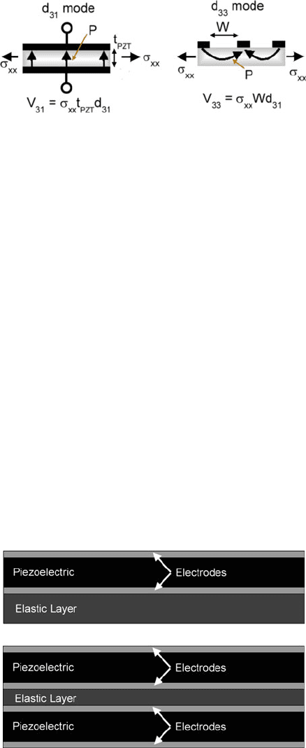
design. Generally, MEMS devices utilize one of two operating modes, defined by
the primary piezoelectric coefficients employed. The “d
33
” mode devices feature
interdigitated (IDT) coplanar electrodes that place much of the electric field in the
plane and are typically constructed with the active piezoelectric film on a dielectric
286 R.G. Polcawich and J.S. Pulskamp
Fig. 5.14 Implementation of
d
31
and d
33
modes of
operation
layer (see Fig. 5.14). The “d
31
” mode devices are more common and feature parallel
plate electrodes that place the electric field through the film thickness (3-axis). This
mode exploits the in-plane strain resulting from the d
31
piezoelectric coefficient.
In many bulk actuator designs, such as the multilayer stack actuator, the piezo-
electric stress/strain can be used directly. However, given the small strains, device
sizes, and process-induced variances involved, piezoelectric MEMS devices almost
exclusively utilize s ome form of displacement amplification. The two most common
generic actuator and sensor structures are the unimorph and bimorph, both employ-
ing a form of displacement amplification. The unimorph is a structure that features
an electroded piezoelectric attached to a structural or elastic layer (see Fig. 5.15).
Application of an electric field to the piezoelectric layer leads to flexure of the struc-
ture and applied stresses can also lead to a voltage developed across the electrodes.
The bimorph (see Fig. 5.15) features two active piezoelectric layers that are operated
with opposite sense strain to produce flexure and similarly may be used in sensing
mode like the unimorph. Membrane structures are also quite common in piezoelec-
tric MEMS applications and differ from their electrostatic counterparts largely in
terms of the optimal electrode design to account for the induced strain nature of
operation. Similar to other MEMS transduction t echniques, flexural leverage has
also been implemented to produce larger displacements in piezoelectric MEMS
actuators. This is particularly true for the recently demonstrated in-plane actuator
designs [16].
Fig. 5.15 Piezoelectric
unimorph (top) and bimorph
(bottom). Note: The bimorph
can be used without the
internal elastic layer and
instead using a common
electrode for both
piezoelectric layers
5 Additive Processes for Piezoelectric Materials 287
5.1.3.5 Free Strain and Blocking Force
Before addressing more detailed device models, it is useful to consider the max-
imum possible strain, displacement, and force that can be generated by a piezo-
electric actuator. The free strain represents the piezoelectrically induced strain
obtained in a completely mechanically free (zero force condition) material and
hence is the maximum attainable strain for a given electric field. Equation (5.17)
defines the free strain associated with the d
31
mode of operation where V is the
applied voltage and t
p
is the thickness of the piezoelectric layer. In contrast, the
term “free displacement” refers to the actuator displacement obtained when the
actuator moves in the absence of external forces. The free displacement is there-
fore the maximum possible nonresonant static displacement for a given actuator
design operating under a given electric field. The actual strain, the induced strain, in
the piezoelectric layer will generally be less than the free strain due to the influence
of the nonpiezoelectric components in the actuator.
31
= d
31
E
3
= d
31
V
t
p
(5.17)
The “blocking force” represents the piezoelectrically induced force obtained in
a completely mechanically clamped (zero strain condition) material and hence is
the maximum attainable force for a given electric field. Equation (5.18) defines
the actuation force of an actuator associated with the d
31
mode of operation where
YA
p
is the extensional stiffness of the piezoelectric layer, Y
p
is the elastic modulus
of the piezoelectric, and w is the width of the actuated section. For most MEMS
structures, the appropriate d
ij
or e
ij
coefficient or constant is the “effective” value
discussed in Section 5.1.1. This actuation force can be interpreted as the blocking
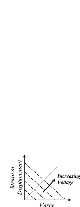
force of the mechanically free piezoelectric layer only. Figure 5.16 illustrates the
force-displacement response for typical actuator designs, with linear stiffness prop-
erties. For a given electric field, the force-displacement response is defined by the
blocking force (zero displacement – x intercept) and the free displacement (zero
force – y intercept). Points along the force-displacement curve represent the possi-
ble conditions where the actuator performs work against an external load. Increasing
the electric field shifts the response up and to the right. The region below the curve
defined by the maximum operating field provides the possible force-displacement
responses of that particular design. Displacement amplification schemes allow the
Fig. 5.16 Plot of the
force/strain (displacement)
relationship for a
piezoelectric actuator
288 R.G. Polcawich and J.S. Pulskamp
designer to trade force and displacement by altering the slope of the curves illus-
trated in Fig. 5.16. This information is useful in determining whether a given
actuator design can drive a given external load.
F
act
=
(
YA
)
p
31
= d
31, f
Y
p
wV (5.18)
5.1.3.6 Cantilever Unimorph Model
There is extensive treatment of modeling piezoelectric sensors and actuators avail-
able in the literature with varying degrees of accuracy and ease of implementation
in design [17–26]. What follows is a model that approximates piezoelectric actua-
tor response that agrees well with finite element analysis and is easily implemented
for design purposes. The complexity of the differential equations describing the
exact piezoelectric response limits the analytical modeling of these devices to the
simplest cases. Although finite element modeling i s typically employed for more
complex device design, analytical models can still provide valuable design insights.
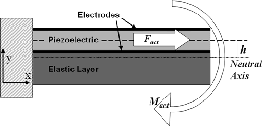
As stated earlier, the unimorph is a structure that features an electroded piezoelectric
attached to a structural layer. A simple unimorph actuator bends due to the piezo-
electrically induced bending moment acting about its neutral axis (see Fig. 5.17).
The actuation force, Equation (5.18), is the resultant of the piezoelectric stresses
and acts near the midplane of the piezoelectric layer. The mechanical asymmetry
of the structure about the piezoelectric layer, due to the presence of the structural
layer, leads to the generation of the actuation moment. In the case of a cantilevered
actuator (see Fig. 5.17) the sense of the strain within the piezoelectric layer and the
relative position of the line of action of the actuation force with respect to the struc-
ture’s neutral axis determine the direction of motion. Equation (5.19) defines the
piezoelectric actuation moment where h is the distance between the line of action of
the actuation force and the relevant neutral axis of the composite actuator.
M
act
= F
act
h = d
31, f
Y
p
wVh (5.19)
Fig. 5.17 Schematic representative of a thin film piezoelectric unimorph cantilever

5 Additive Processes for Piezoelectric Materials 289
Equation (5.20) defines h in terms of the location of the actuation force, y
Fact
,
and the neutral axis referenced to the same arbitrary axis. For most structures, the
actuation force is assumed to act at the midplane of the piezoelectric layer.
h = y
Fact
−¯y (5.20)
A convenient method for treating composite structures in flexure is the trans-
formed section method [27]. This method converts the various dissimilar material
layers of the composite to a common material with a transformed cross-section. The
layers of the new cross-section have altered widths to maintain the same stiffness
properties as the previous sections with the beam now of a homogeneous material.
This cross-section is mechanically equivalent, in flexure, to the original compos-
ite beam but may be treated with conventional analysis. The method permits the
determination of the location of the neutral axis, bending stresses, and flexural stiff-
ness properties of the composite structure. An arbitrary material in the composite
is chosen as the homogeneous material of the transformed cross-section. The cross-
sectional areas of the new layers of a composite comprised of individually isotropic
elastic materials are given by Equation (5.21) where w
i
and t
i
are the original width
and thickness, respectively, of the ith layer, Y
i
is the modulus of elasticity, and Y
ref
is the modulus of the reference layer.
A
i
= w
i
t
i
Y
i
Y
ref
(5.21)
The location of the bending neutral axis is given by Equation (5.22) where y
i
is
the distance from each layer’s centroid to some arbitrary reference axis and A
tot
is
the total area of the transformed section.
¯y =
A
i
y
i
A
tot
(5.22)
In the case of the cantilevered actuator, the equivalent loading of the piezoelec-
tric is that of moment applied at the end of the electroded beam. The linear free
displacement of the cantilevered unimorph actuator is described, from Bernoulli–
Euler beam theory, by Equation (5.23) where L is the length of the electrode, M
act
is the bending moment acting on the actuator, and YI
c
is the flexural rigidity of the
composite actuator.
y
tip
=
M
act
L
2
2YI
c
=
d
31, f
Y
p
wVhL
2
2YI
c
(5.23)
For many designs, the cantilevered piezoelectric actuator is capable of extremely
large displacements. The dominant mechanical nonlinearity in these cases is due
to the geometric (small displacement) nonlinearity. Again, for the case of the

290 R.G. Polcawich and J.S. Pulskamp
cantilevered piezoelectric actuator with a constant end applied moment, this non-
linearity is easily described [28]. Equations (5.24) and (5.25) describe the vertical
and horizontal free displacements, respectively.
y
tip
=
YI
c
M
act
1 − cos
M
act
L
YI
c
(5.24)
x
tip
= L −
YI
c
M
act
sin
M
act
L
YI
c
(5.25)
The flexural rigidity of the composite YI
c
describes the bending stiffness of the
actuator and is the product of the modulus of elasticity and the moment of inertia
(second moment of area) of the beam with respect to the neutral axis. Employing the
transformed section method and the parallel axis theorem, Equation (5.26) defines
YI
c
where I
i
is the moment of inertia of the ith layer about its own centroid and d
i
is
the distance between the ith layer’s centroid and the neutral axis [27].
YI
c
= Y
ref
I
i
+ A
i
d
2
i
(5.26)
Some problems, such as modal analysis, often require an equivalent modulus
of elasticity of the composite structure. In the preceding discussion, use of the
transformed section method defined the section properties in terms of an arbi-
trary homogeneous material. An equivalent modulus of elasticity Y
c
is defined
by Equation (5.27) which applies to structures where the separate layers behave
mechanically in parallel.
Y
c
=
Y
i
V
i
V
tot
(5.27)
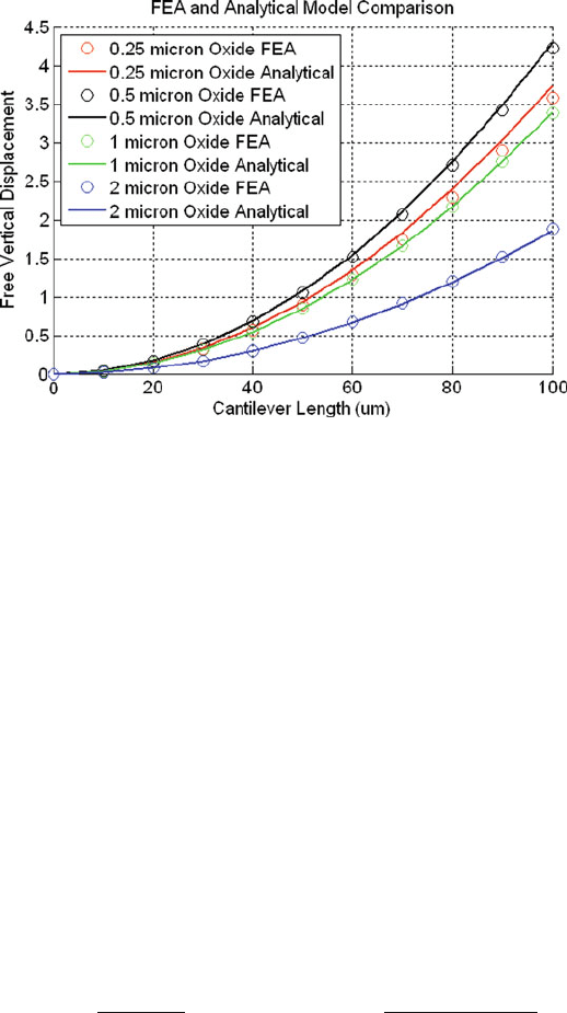
The method just described agrees well with finite element analysis. Figure 5.18
compares the results of a commercially available FEA package and the analytical
model above for a d
31
mode unimorph cantilever with a PZT active layer operating
at 5 V for various ratios of piezoelectric to structural layer. The unimorph (or struc-
ture) is a silicon dioxide/platinum/PZT/platinum prismatic beam. The FEA model
utilized 3-D ten-node tetrahedral structural and directly coupled field solid elements.
The analytical model generally agrees within 1–3% of the finite element analysis.
As discussed previously in Section 5.1.1, the film clamping effects in the major-
ity of piezoelectric MEMS structures result in effective d
31, f
coefficients and e
31, f
constants. The 1-D analytical model described above utilizes these values directly
as these terms directly relate, for example, d
31, f
, the 1-axis strain response in the
structure to the electric field applied along the 3-axis. However, in a 2- or 3-D FEA
analysis that accommodates the full piezoelectric coefficient matrix, the actual coef-
ficients should be specified using Equation (5.12). The method can also easily be
modified to describe the response of bimorph devices.
5 Additive Processes for Piezoelectric Materials 291
Fig. 5.18 Comparison of FEA and analytical modeling of piezoelectric unimorphs
5.1.3.7 Actuator Force Generation Against External Loads
The force exerted by a piezoelectric actuator depends upon the particular configu-
ration used. Two general cases of interest are of a cantilever exerting a purely axial
force against an external load and that of a unimorph or bimorph acting against a
normal load. A symmetric composite actuator that is capable of extensional dis-
placements only can be used to drive a MEMS flexure. In this case, the force
produced by the actuator is related to the actuation force of the actuator and the
ratio of the stiffnesses of the actuator and flexure. Equation (5.28) relates the force
exerted by the actuator on a MEMS flexure where k
ext
is the spring constant of the
flexure and L
act
is the dimension of the actuator along the axis of displacement.
The equation illustrates the importance of the actuator stiffness when designing an
actuator for driving a specific load. When the actuator is very much stiffer than the
flexure, the actuator is unconstrained, the force exerted by the actuator is zero, and
no work has been done on the load (F = 0). At the other extreme, when the flex-
ure is much stiffer than the actuator, the actuator is completely clamped, the force
exerted by the actuator is equal to the blocked force, and again no work has been
done (x = 0).
F = F
act
1 −
k
act
k
act
− k
ext
= d
31, f
Y
p
wV
1 −
Y
i
A
i
Y
i
A
i
− L
act
k
ext
(5.28)
Similar behavior is observed for a unimorph or bimorph acting against a normal
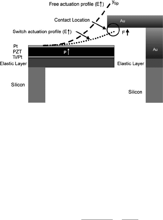
load. This scenario is encountered in most piezoelectric RF MEMS switch designs
where a unimorph or bimorph actuator closes a pair of electrical contacts through
vertical displacements. The PZT RF MEMS switch design of Polcawich et al. [29]
292 R.G. Polcawich and J.S. Pulskamp
Fig. 5.19 Schematic diagram of contact loading for a piezoelectric switch actuator
features a pair of unimorph actuators mechanically coupled at their free ends to a
structure containing the switch contacts. Voltage applied to the actuators vertically
displaces the contacts up into a set of contact cantilevers. Figure 5.19 illustrates a
simple model of this structure depicting a partially electroded cantilever unimorph
with a normal contact force at the switch contact location (this assumes the contact
cantilever is rigid; i.e., infinite k
ext
)[30]. In this case, the f orce exerted by the actua-
tors can be approximated by the product of the actuator stiffness and the difference
between the initial gap and the free displacement. Equation (5.29) relates the force
exerted by the actuator on the contact beam for the simple case where the force is
exerted at the location of the end of the electrode and g
o
is the initial gap between
the actuator and the contact.
F = k
act
y
tip
− g
o
=
3d
31, f
Y
p
wVh
2L
act
−
3g
o
YI
c
L
3
act
(5.29)
5.1.3.8 Piezoelectric Sensing
The preceding discussion described basic models for the behavior of piezoelec-
tric actuators by use of the converse or indirect effect (Equations (5.6) and (5.8)).
Piezoelectric materials may also be utilized for sensing and power harvesting
applications. The constitutive equation for the direct effect, Equations (5.7) and
(5.9), describe the dependence of the electric displacement on external stresses.
Piezoelectric sensors generally measure this response either through the voltage
developed on open-circuited electrodes or by the current (or charge via integration)
through short-circuited electrodes with the aid of additional signal-conditioning
electronics. Equation (5.30) describes the charge developed on the electrodes in
terms of the electric displacement where the integration is carried out over the entire
electrode area of the piezoelectric.
5 Additive Processes for Piezoelectric Materials 293
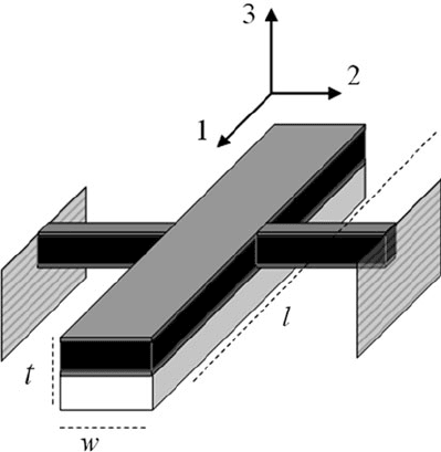
Fig. 5.20 Resonant free–free
beam device
q =
[D
1
D
2
D
3
]
⎡
⎣
dA
1
dA
2
dA
3
⎤
⎦
(5.30)
Consider a large aspect ratio piezoelectric structure vibrating in a length exten-
sional mode (see Fig. 5.20). Equation (5.31) describes the charge developed on the
electrodes of such a structure where the only nonzero stress is along the 1-axis that
is normal to the plane of the beam structure. Carrying out the integration on the sec-
ond term on the right-hand side and substituting the definition from electrostatics of
voltage in terms of electric field (note the negative sign), we obtain Equation (5.32).
The first term is the charge due to the static capacitance of the piezoelectric sensor
and the second is the piezoelectrically induced charge due to the external stress. This
expression describes the essence of piezoelectric sensor operation.
q =−
⎛
⎝
w
0
L
0
(
d
31
σ
x
)
dxdy +
w
0
L
0
ε
o
ε
33
E
3
dxdy
⎞
⎠
(5.31)
q = C
p
V −
w
0
L
0
(
d
31
σ
x
)
dxdy (5.32)
The open circuit voltage is obtained by setting the charge to zero and solving
for the voltage across the electrodes (see Equation (5.33)). The short-circuit total
