Durst F. Fluid Mechanics: An Introduction to the Theory of Fluid Flows
Подождите немного. Документ загружается.


18.7 Turbulence Models 573
18.7.4 One-Equation Eddy Viscosity Models
The class of turbulence models, discussed in Sect. 18.7.3, tries to describe the
momentum transport properties of turbulent flows with the help of a single
parameter, namely the Prandtl mixing length. The latter is introduced into
the considerations in a geometry-specific way and is stated in the form of
an algebraic equation, where the velocity characteristic of the turbulence is
introduced via the mixing length and the gradient of the mean velocity field.
In order to achieve a model expansion, the characteristic velocity typical of
the turbulent momentum transport is set as follows:
u
c
= k
1
2
with k =
1
2
u
i
u
i
. (18.207)
With the characteristic length l
c
of one-equation models, thus ν
T
=(l
c
)
1
k
1
2
results. Here k is the local turbulent kinetic energy, which is described by the
following transport equation:
U
i
∂k
∂x
i
=
∂
∂x
i
*
−
p
u
i
ρ
+2ν
u
j
∂u
j
∂x
i
−
1
2
u
j
u
j
u
i
+
−
u
i
u
j
∂U
j
∂x
i
−2ν
∂u
j
∂x
i
2
(18.208)
so that the turbulent transport properties in (18.208) change with the modi-
fications of turbulence in a flow field. It is customary in turbulence modeling
to rewrite the above equation as follows:
U
i
∂k
∂x
i
=
diffusion
−
∂D
i
∂x
i
+
production
P −
dissipation
, (18.209)
where the following relationships hold:
D
i
= −
*
−
p
u
i
ρ
+2ν
u
j
∂u
j
∂x
i
−
1
2
u
j
u
j
u
i
+
(18.210)
and
P = −
u
i
u
j
∂U
j
∂x
i
; = −ν
∂u
j
∂x
i
∂u
j
∂x
i
. (18.211)
With the modeling assumptions for D
i
, P and , customary in present-day
turbulence modeling research, the following modeled k equation results:
U
i
∂k
∂x
i
=
∂
∂x
i
ν +
ν
T
σ
k
∂k
∂x
i
diffusion
+ ν
T
∂U
j
∂x
i
+
∂U
i
∂x
j
∂U
j
∂x
i
production
− C
D
k
3
2
(l
c
)
1
dissipation
.
(18.212)
574 18 Turbulent Flows
The second term on the right-hand side of (18.212) represents the production
of turbulence by the mean flow field, which was stated as follows:
−
u
i
u
j
∂U
j
∂x
i
= ν
T
∂U
j
∂x
i
+
∂U
i
∂x
j
∂U
j
∂x
i
. (18.213)
The first term on the right-hand side of (18.212) also contains σ
k
,aquantity
which indicates how the turbulent diffusion of k is related to the turbulent
momentum diffusion ν
T
, i.e. σ
k
states the relationship of turbulent momen-
tum dissipation to energy dissipation. The third term on the right-hand side
of (18.212) states the turbulent dissipation. For this term, order of magnitude
considerations suggest, for equilibrium flows:
P ∼
u
3
c
l
c
∼ ; = C
D
k
3
2
(l
c
)
1
. (18.214)
The constants introduced into this one-equation turbulence model have to be
determined from experiments. Here, one makes use of the two-dimensional
form of the k equation for a boundary-layer flow:
U
x
∂k
∂x
+U
y
∂k
∂y
=
∂
∂y
ν +
ν
T
σ
T
∂k
∂y
+ ν
T
∂U
x
∂y
2
−c
D
k
3
2
(l
c
)
1
. (18.215)
In the turbulent equilibrium range of the flow (inertial sub-range), it holds
that P = , i.e. it can be stated that:
ν
T
dU
x
dy
2
=+C
D
k
3
2
(l
c
)
1
. (18.216)
On taking into account that the following relationships are valid:
τ
xy
= −ρν
T
dU
x
dy
≈−τ
w
(18.217)
and considering that τ
w
/ρ = u
2
τ
, one obtains τ
w
/ρ
∂U
x
∂y
= c
D
k
3/2
(l
c
)
1
,and
with
∂U
x
∂y
≈
k
1/2
(l
c
)
1
it can be stated that
k
+
=
k
u
2
τ
= C
−
1
2
D
. (18.218)
As in Sect. 18.7.3, for the one-equation k-l model, assumptions were chosen
in turbulence considerations which “in wall boundary layers” take into ac-
count the closeness of the wall and which lead to differing assumptions for
(l
c
)
1
values, depending on whether one considers the diffusion term or the
dissipation term:
18.7 Turbulence Models 575
(l
c
)
1,ν
= C
1
4
D
κy [1 − exp (−A
ν
R
T
)] with A
ν
=0.016 (18.219)
and
(l
c
)
1,D
= C
1
4
D
κy [1 − exp (−A
D
R
T
)] with A
D
=0.26, (18.220)
where R
T
=
k
1
2
y
ν
represents the Reynolds number formed by wall
disturbance:
(l
c
)
1
= l
P
C
1
4
D
. (18.221)
From boundary layer data, the value C
D
≈ 0.09 results. With this value,
it is now possible to integrate the Reynolds equations employing the k-l
one-equation turbulence model.
In order to determine the C
D
value, the equilibrium region of a boundary
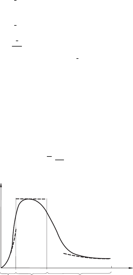
layer was employed. Figure 18.18 shows where this region is located.
It is also customary to employ other characteristic ranges of turbulent
flows to determine the “free constants” in turbulence models. Altogether the
following ranges are available, introduced here by terms customary in the
English literature on turbulence.
Equilibrium range:
0=P − . (18.222)
Decay range:
U
i
∂k
∂x
i
= −. (18.223)
Wall near
region
Core region
Equilibrium
region
0
h
y
K
Fig. 18.18 Ranges of turbulent channel flow
576 18 Turbulent Flows
Rapid distortion range:
U
i
∂k
∂x
i
= P. (18.224)
The above equations are useful in discussions of different turbulent flow
regions.
18.7.5 Two-Equation Eddy Viscosity Models
Practical experience with turbulence models shows that, as far as their
general applicability is concerned, the k-l one-equation model represents a
considerable improvement over the zero-equation models. However, very good
computations of turbulent flows can only be carried out by zero- and one-
equation models when small flow accelerations or decelerations occur, i.e.
flows with strong pressure gradients can only be computed in an unsatisfac-
tory way with k-l one-equation models. Experience shows that the limitations
of the applicability of k-l one-equation models are due to the algebraic form
of the characteristic length scale l, which often means that the applicabil-
ity remains restricted to such flows which were applied for deriving the k-l
one-equation models. This is the reason for the introduction of two-equation
eddy viscosity models. One of these models is the k- model, which is based
on the solution of the following two differential equations:
k equation:
∂k
∂t
+
u
i
∂k
∂x
i
Dk
Dt
= −u
i
u
j
∂U
j
∂x
i
P
−
∂
∂x
i
u
i
u
j
u
j
2
+
P
ρ
T
−ν
∂u
j
∂x
i
∂u
j
∂x
i
+ν
∂
2
k
∂x
i
∂x
i
D
,
(18.225)
where P = production term, T = transport term and = dissipation term
and D = diffusion term.
equation:
∂
∂t
+
u
i
∂
∂x
i
= −2ν
∂u
j
∂x
i
∂u
k
∂x
i
∂U
j
∂x
k
P
1
− 2ν
∂u
j
∂x
k
∂u
j
∂x
i
∂U
k
∂x
i
P
2
−2νu
k
∂u
j
∂x
i
∂
2
U
j
∂x
k
δx
i
P
3
− 2ν
∂u
j
∂x
i
∂u
k
∂x
i
∂u
j
∂x
k
P
4
−
∂
∂x
k
νu
k
∂u
j
∂x
i
∂u
j
∂x
i
T
−
∂
∂x
k
2ν
ρ
∂u
k
∂x
i
∂p
∂x
i
M
18.7 Turbulence Models 577
−2ν
2
∂
2
u
j
∂x
i
δx
k
∂
2
u
j
∂x
i
δx
k
γ>0
+ ν
∂
2
∂x
k
δx
k
D
. (18.226)
The eddy viscosity can be defined with k and , i.e. with u
c
= k
1/2
and
l
c
=
k
3/2
, as follows:
ν
T
= C
µ
k
2
.
Here, k and are determined from the above-modeled differential equations.
In this context, it is useful to know that in turbulence modeling the above-
cited equation for k is considered to be sufficiently well modeled as concerns
practical computations, whereas similarly satisfactory modeling assumptions
do not exist for the equation. The model equations often used in present-
day flow computations are the following:
k equation:
∂k
∂t
+
U
i
∂k
∂x
i
= ν
t
∂
U
j
∂x
i
+
∂
U
i
∂x
j
∂
U
j
∂x
i
+
∂
∂x
i
ν
t
σ
K
∂k
∂x
i
− + ν
∂
2
k
∂x
i
∂x
i
.
(18.227)
With ν
t
as
ν
t
∼
=
0.09
k
2
.
equation:
∂
∂t
+
U
i
∂
∂x
i
= c
1
R
ν
t
∂
U
j
∂x
i
+
∂
U
i
∂x
j
∂
U
j
∂x
i
− c
2
f
2
k
+
∂
∂x
i
ν
t
σ
∂
∂x
i
+ ν
∂
2
∂x
i
∂x
i
. (18.228)
Here, the modeling of the last term in the equation is based on the
assumption:
P ∼ k
k
1
2
l
c
; ν
U
λ
2
2
=
2
k
. (18.229)
As concerns the boundary layer formulation of the Reynolds and k- turbu-
lence model equations, valid for high Reynolds numbers, they can be given
as follows:
∂U
∂x
+
∂V
∂y
=0, (18.230)
U
∂U
∂x
+ V
∂U
∂y
= F
x
−
1
ρ
∂P
∂x
+
∂
∂y
(ν + ν
T
)
∂U
∂y
, (18.231)
U
∂K
∂x
+ V
∂K
∂y
=
∂
∂y
ν
T
σ
K
∂K
∂y
+ ν
T
∂U
∂y
2
− , (18.232)
578 18 Turbulent Flows
U
∂
∂x
+ V
∂
∂y
=
∂
∂y
ν
T
σ
∂
∂y
+ C
1
ν
T
K
∂U
∂y
2
− C
2
2
K
, (18.233)
ν
T
= C
µ
K
2
,
where C
µ
=0.09, σ
K
=1.0, σ
=1.3, C
1
=1.45, C
2
=2.0.
In order to determine c
µ
,theansatzν
T
∂U
∂y
2
= ; c
µ
= c
D
=
k
u
2
τ
2
=
0.09 again holds. This can also be determined from measurements of wall
boundary layers.
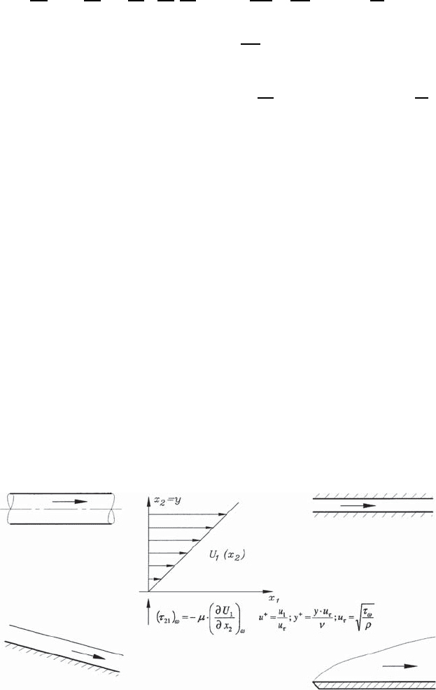
18.8 Turbulent Wall Boundary Layers
Turbulent boundary-layer flows, whose essential properties are determined by
the presence of a wall, are called wall boundary layers. As classic examples
one can cite
• Internal flows: plane channel flows and pipe flows
• External flows: plane plate flows and film flows
These flows are sketched in Fig. 18.19. Their essential feature is the momen-
tum loss to a wall which is characteristic of all flows in Fig. 18.19, i.e. wall
momentum loss exists in all the indicated flow cases and, in addition, the
properties of the fluid, the density ρ and the dynamic viscosity µ characterize
the fluid.
In order to discuss the properties of turbulent boundary layers in an
introductory way, the fully developed, two-dimensional, plane, turbulent
Pipe flows
Film flows
Plane chamber flows
Wall boundar
y
la
y
ers
Normalisation of the flow
data yields
u
+
and
y
+
:
All these flows are
characterised by
momentum losses to walls
Fig. 18.19 Examples of internal and external wall boundary layers
18.8 Turbulent Wall Boundary Layers 579
channel flow is subjected to more detailed considerations below. From the
Reynolds equations (see Sect. 18.5.2), the following reduced set of equations
can be deduced for fully developed, plane channel flows with the above-cited
properties:
x
1
− momentum equation: 0 = −
∂P
∂x
1
+
d
dx
2
µ
d
U
1
dx
2
− ρu
1
u
2
. (18.234)
x
2
− momentum equation: 0 = −
∂P
∂x
2
− ρu
2
2
. (18.235)
x
3
− momentum equation: 0 = −
d
dx
2
u
2
u
3
. (18.236)
The last partial differential equation (18.236) can be integrated and yields,
because of the wall boundary condition
u
2
u
3
= 0, that the correlation u
2
u
3
in the entire plane perpendicular to the plates of the channel has the value
u
2
u
3
=0.
The integration of the second differential equation (18.235) yields
P (x
1
,x
2
)=P
w
(x
1
) − ρu
2
2
, (18.237)
where ρ
u
2
2
= f (x
2
), since in the x
1
-direction the flow was assumed to be
fully developed. Nevertheless, the above relationship expresses that the pres-
sure in a turbulent channel flow changes slightly over the cross-section. The
change proves to be so small, however, that it can be neglected for practical
considerations of the properties of fully developed, two-dimensional, plane,
turbulent channel flows. Thus, from (18.237) the following results for the
pressure gradient:
∂P
∂x
1
≈
dP
w
dx
1
. (18.238)
Inserted in (18.234), one obtains:
dP
w
dx
1
=
d
dx
2
µ
d
U
1
dx
2
− ρu
1
u
2
τ
ges
=
dτ
ges
dx
2
. (18.239)
If one introduces, for scaling the above equations, the velocity and length
scales:
u
τ
=
0
τ
w
ρ
and !
e
=
ν
u
τ
(18.240)
the momentum equation (18.239) can be written in general form as follows:
dU
+
1
dy
+
=1−
y
+
Re
τ
+
u
1
u
2
+
. (18.241)
580 18 Turbulent Flows
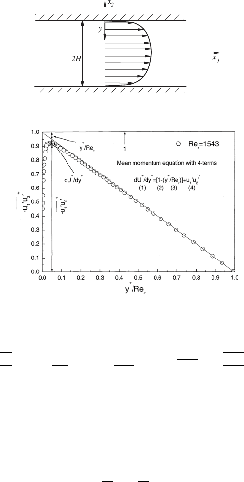
Fig. 18.20 Fully developed turbulent, plane channel flow
Fig. 18.21 Terms of the momentum equation for two-dimensional channel flow
Here the wall coordinate y is introduced: y = H − x
2
.
U
+
1
=
U
1
u
τ
; y
+
c
=
yu
τ
ν
; Re
τ
=
Hu
τ
ν
and
u
1
u
2
+
=
u
1
u
2
u
2
τ
. (18.242)
With these standardized quantities introduced into (18.242), (18.241) can be
derived. The latter relation comprises four terms which can all be seen in
Fig. 18.21.
In Fig. 18.21, the horizontal line represents the value 1. The quantity
−y
+
/R e
τ
and the quantity −u
1
u
2
in the equation and also dU
+
/ dy
+
are
also shown in Fig. 18.21.
From (18.239), we obtain
τ
ges
=
τ
w
H
x
2
=
τ
w
H
(h − y)
so that the different terms stated in (18.241) can be shown as in Fig. 18.21.
It is evident that the term dU
+
1
/dy
+
represents, over wide ranges of the flow,
the smallest value in the standardized momentum equation (18.241).
18.8 Turbulent Wall Boundary Layers 581
In order to obtain information on dU
+
1
/dy
+
for plane channel flows, laser
Doppler and hot wire measurements were carried at the Institute for Fluid
Mechanics (LSTM) of Friedrich-Alexander-University, Erlangen-N¨urnberg to
achieve U
1
(y) distributions experimentally. In connection with detailed shear
stress measurements, the presentation of the normalized measured values of
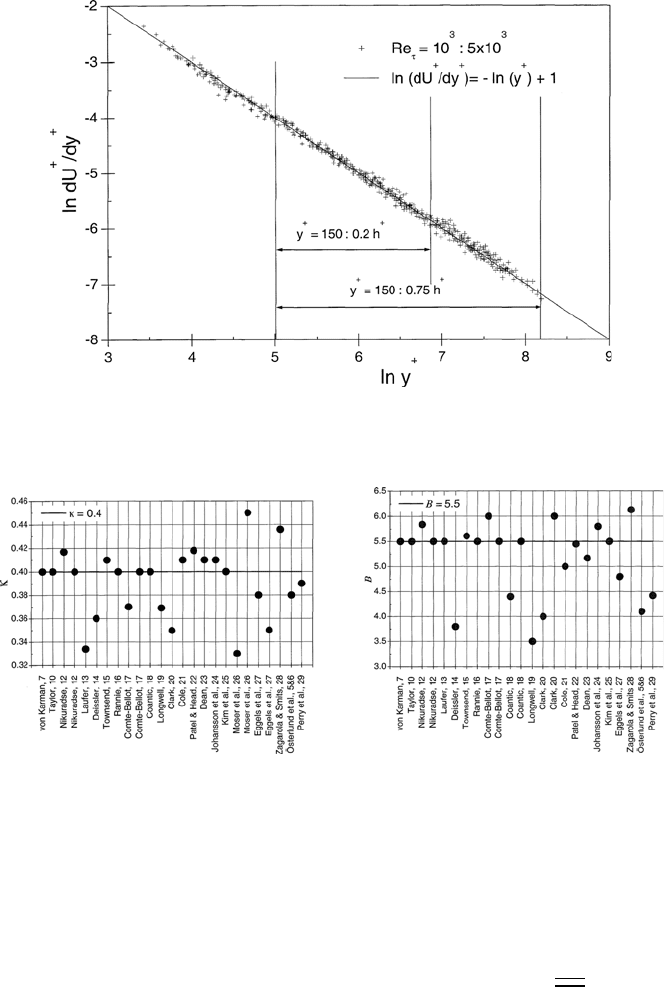
the velocity gradient was achieved in the form
ln
dU
+
1
dy
+
= f
!
ln y
+
"
(18.243)
and from this it was determined that, for high Reynolds numbers, the mea-
sured and normalized mean velocity gradients plotted in Fig. 18.21 can be
described as follows:
ln
dU
+
1
dy
+
= −ln y
+
+1≡ ln
e
y
+
. (18.244)
From this, U
+
1
= e ln y
+
+ B can be obtained, i.e. the standardized velocity
distribution in a plane channel flow can, over a wide range of the channel
cross-section, be described by a logarithmic velocity distribution:
U
+
1
=
1
κ
ln y
+
+ B with
κ =1/e
B =10/e
. (18.245)
These values were found through the experimental investigations at LSTM
Erlangen.
Figure 18.22 shows that the double-logarithmic plotting yields a line with
gradient −1. This is due to the fact that the logarithmic law is valid for the
normalized velocity distribution.
In the literature there has been a number of investigations to determine
the value of κ and the additive constant B to represent with these the loga-
rithmic boundary velocity law. The following represents a summary of these
investigations and the resultant values. The large variation in the values is
mainly due to the use of measurement techniques which do not permit suffi-
ciently local measurements of the mean flow velocities. Furthermore, effects
which arise from flows of low Reynolds numbers were included in the eval-
uations of κ and B in some literature data. If one considers all the possible
influences, i.e. permits only reliable hot wire and laser Doppler measurements
to enter the evaluations, then one obtains the values indicated in (18.245) for
κ and B (Fig. 18.23).
If one employes only reliable measurements for dU
+
1
/dy
+
, the relationship
stated in (18.241) allows the determination of (
u
1
u
2
)
+
values for turbulent
channel flows. Distributions of these turbulent transport terms, plotted in a
normalized form, are shown in Fig. 18.24.
By means of a plane channel measuring test section with glass side
walls and the use of an LDA velocity-measuring system, information on the
582 18 Turbulent Flows
Fig. 18.22 Representations of experimental investigations for determining the
logarithmic wall law
Fig. 18.23 Scatter of the κ and B values in the experimental determination of
U
+
1
= f (y
+
) for wall boundary layers
turbulent velocity fluctuations existing in flow direction, could also be ob-
tained at LSTM Erlangen. This information is shown in a summarized way
in Fig. 18.25. In this figure they are compared with corresponding results of
numerical flow computations.
Detailed measurements carried out at LSTM Erlangen have confirmed in-
teresting new results, e.g. that the local turbulence intensity
u
1
2
/U
1
does
not adopt a constant wall value. The result shows that the constant wall
value of this velocity ratio depends on the Reynolds number of the flow (see
Fig. 18.26). Although small discrepancies can be seen as compared with the