Durst F. Fluid Mechanics: An Introduction to the Theory of Fluid Flows
Подождите немного. Документ загружается.

15.2 Creeping Fluid Flows Between Two Plates 431
are carried out for viscous flows of small Reynolds numbers, employing the
equations in (15.4). The considerations are carried out up to the computations
of forces, to make it clear how small Reynolds number flows can be treated in
a complete way. The computations of forces require derivations of the pres-
sure distributions on the surface of bodies and also computations of the local
momentum losses of flows at walls. The chosen examples are aimed to give a
suitable introduction to the treatments of flows of small Reynolds numbers.
Solutions of other creeping flow examples, going beyond the treatments in
this chapter, are easily possible and are often described extensively in books
on fluid mechanics, see refs. [15.1] to [15.7]. Hence, no further considerations
of more complex flows are needed here.
15.2 Creeping Fluid Flows Between Two Plates
In this section, the flow of a viscous fluid between two parallel plates is
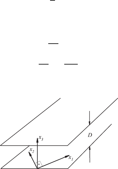
considered, whose distance D can be regarded as being very small (Fig. 15.1).
When the area-averaged mean flow velocity
˜
U =
1
A
#
A
U
i
dA
i
(15.5)
is also small, the conditions for the employment of the following differential
equations exist. When ρ = constant holds, then one can write
∂U
i
∂x
i
= 0 (15.6)
∂P
∂x
j
= µ
∂
2
U
j
∂x
i
2
, (15.7)
i.e. the Stokes differential equations can be employed to treat the flow between
two parallel plates.
Fig. 15.1 The diagram shows the plates and the coordinate system for a flow between
plates

432 15 Fluid Flows of Small Reynolds Numbers
This set of differential equations reads, written in full, for j =1, 2, 3:
∂U
1
∂x
1
+
∂U
2
∂x
2
+
∂U
3
∂U
3
= 0 (15.8)
j =1:
∂P
∂x
1
= µ
∂
2
U
1
∂x
1
2
+
∂
2
U
1
∂x
2
2
+
∂
2
U
1
∂x
3
2
(15.9)
j =2:
∂P
∂x
2
= µ
∂
2
U
2
∂x
1
2
+
∂
2
U
2
∂x
2
2
+
∂
2
U
2
∂x
3
2
(15.10)
j =3:
∂P
∂x
3
= µ
∂
2
U
3
∂x
1
2
+
∂
2
U
3
∂x
2
2
+
∂
2
U
3
∂x
3
2
. (15.11)
The above equations are valid within the limits −∞ <x
1
,x
2
< +∞ and
0 ≤ x
3
≤ D. In addition, the flow in the x
1
and x
2
directions is assumed
to be fully developed, i.e. ∂U
j
/∂x
1
=0and∂U
j
/∂x
2
= 0, so that one can
deduce from the continuity equation:
∂U
3
∂x
3
=0 ; U
3
= constant. (15.12)
Because U
3
=0forx
3
=0andx
3
= D, U
3
= 0 holds in the entire flow region
between the two channel walls.
Due to the existence of fully developed flow conditions in the x
1
and x
2
directions, the following differential equations hold:
∂P
∂x
1
= µ
∂
2
U
1
∂x
3
2
;
∂P
∂x
2
= µ
∂
2
U
2
∂x
3
2
;
∂P
∂x
3
=0. (15.13)
From these equations, one obtains for U
1
:
U
1
=
1
µ
∂P
∂x
1
x
2
3
2
+ C
1
x
3
+ C
2
(15.14)
and for U
2
U
2
=
1
µ
∂P
∂x
2
x
2
3
2
+ C
3
x
3
+ C
4
. (15.15)
The integration constants C
1
and C
2
can be determined from the boundary
conditions:
U
1
=0forx
3
=0andx
3
= D ; C
2
=0andC
1
= −
D
2µ
∂P
∂x
1
.
Thus one can derive for U
1
:
U
1
= −
1
2µ
∂P
∂x
1
x
3
(D − x
3
) (15.16)

15.3 Plane Lubrication Films 433
and likewise U
2
can be determined as:
U
2
= −
1
2µ
∂P
∂x
2
x
3
(D −x
3
). (15.17)
The equations for U
1
and U
2
show that the velocities differ only due to the
pressure gradients imposed in the x
1
and x
2
directions.
With the aid of the above solutions for U
1
and U
2
, some further interesting
considerations can be carried out. The result is that the cross-sectional mean
velocities can be determined as follows, according to (15.5):
˜
U
1
(x
1
,x
2
)=−
D
2
12µ
∂P
∂x
1
˜
U
2
= −
D
2
12µ
∂P
∂x
2
, (15.18)
where
˜
U
1
and
˜
U
2
are the area-averaged velocities in the x
1
and x
2
directions.
On introducing the potential φ(x
1
,x
2
), driving the mean flow field to an
extent that φ(x
1
,x
2
)=−
D
2
12µ
P (x
1
,x
2
) holds, then the following relationship
can be stated:
˜
U
1
=
∂φ
∂x
1
and
˜
U
2
=
∂φ
∂x
2
. (15.19)
These relationships between the components of the mean velocity field and
the potential φ, express for the area-averaged fluid velocity, the driving force
to be the differentials of φ. This essentially suggests that the flow can be
regarded as having a block profile and is formally running, like the vorticity-
free flow of an ideal fluid (potential flow).
15.3 Plane Lubrication Films
Already daily experience shows that a fluid film between two plates has pos-
itive properties, as far as the sliding of one plate on another is concerned.
This provides insight into the film action, suggesting that the forces acting
on two solid plates, that are exposed to a gliding process, can be reduced by
lubrication films. One further notices that a fluid film placed between two
plates is able to absorb considerable forces. All these considerations make it
clear why fluid films can be used in so-called slide bearings in mechanical
systems, in order to make sliding and also rotating machine elements work
in practice. In order to understand the principal function of lubrication films
and also their properties, the flow in a very thin film which develops between
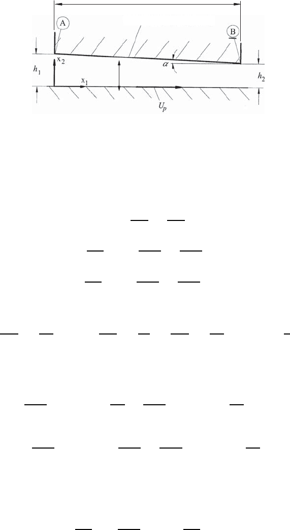
two sliding plates is investigated. Such a film which develops below a plate,
having a length l and leading to film thicknesses h
1
and h
2
at the beginning
and end of the plate, respectively, is plotted in Fig. 15.2. Due to h
2
= h
1
,
an angle of inclination α develops by which the upper plate is inclined with
respect to the lower plate. Thus, the film thickness h(x
1
) is determined by
the film and its motion. Moreover, in the treatment of the film motion, the
lower plate moves at a velocity U
P
relative to the upper plate.
434 15 Fluid Flows of Small Reynolds Numbers
Lower plate (is moving)
Liquid film
l
h
(x
)
1
Upper plate (is fixed)
Fig. 15.2 Considerations of the fluid flow between two plates (basic flow of tripol-
ogy). U
P
= velocity of the moving lower plate; α = inclination angle between the
plates; R(x
1
) = variation of plate distance
For the flow between the inclined plates, induced by the motion of the lower
plate in Fig. 15.2, (15.8)–(15.11) hold the Stokes’ equations in the following
form, because U
3
=0:
0=
∂U
1
∂x
1
+
∂U
2
∂x
2
(15.20)
∂P
∂x
1
= µ
∂
2
U
1
∂x
1
2
+
∂
2
U
1
∂x
2
2
(15.21)
∂P
∂x
2
= µ
∂
2
U
2
∂x
1
2
+
∂
2
U
2
∂x
2
2
. (15.22)
Orders of magnitude considerations of the terms in (15.20) yield:
∂U
1
∂x
1
≈
U
P
l
and
∂U
2
∂x
2
=
U
2
h
=
∂U
1
∂x
1
=
U
P
!
U
2
≈ U
P
h
l
.
(15.23)
Because (h/l) 1, U
2
U
P
(thin lubrication film), the order of U
2
can be
computed. Similar considerations for the terms in (15.21) and (15.22) yield:
∂
2
U
1
∂x
1
2
=term1 ≈
U
P
l
2
;
∂
2
U
1
∂x
2
2
=term2 ≈
U
P
h
2
(15.24)
∂
2
U
2
∂x
1
2
=term3 ≈
U
P
h
l
3
;
∂
2
U
2
∂x
2
2
=term4 ≈
U
P
lh
. (15.25)
Comparisons of terms 1–4 in (15.24) and (15.25) show that term 2 domi-
nates and that therefore the following simplified forms of (15.21) and (15.22)
describe, sufficiently well, the film flow between two plates indicated in
Fig. 15.2:
∂P
∂x
1
= µ
∂
2
U
1
∂x
2
2
and
∂P
∂x
2
=0. (15.26)

15.3 Plane Lubrication Films 435
For the induced film flow, the following boundary conditions hold:
x
2
=0 : U
1
(x
1
, 0) = U
P
and x
2
= h(x
1
): U
1
(x
1
,h)=0. (15.27)
Integrating ∂P/∂x
2
=0yieldsP = Π(x
1
), so that the differential equation
for the velocity field reads
dΠ
dx
1
= µ
∂
2
U
1
∂x
2
2
; U
1
(x
1
,x
2
)=
1
2µ
dΠ
dx
1
x
2
2
+C
1
x
2
+C
2
. (15.28)
With the boundary conditions in (15.27), the two integration constants in
(15.28) can be derived to read as follows:
C
1
= −
U
P
h(x
1
)
−
1
2µ
dΠ
dx
1
h(x
1
)andC
2
= U
P
. (15.29)
Thus, the following equation for U
1
results:
U
1
(x
1
,x
2
)=
−1
2µ
dΠ
dx
1
x
2
[h (x
1
) − x
2
]+U
P
h (x
1
) − x
2
h (x
1
)
. (15.30)
The constant volume flow rate of the film flow can be computed by
integration:
˙v (x
1
)=
h
#
0
U
1
dx
2
=
−1
12µ
dΠ
dx
1
h
3
(x
1
)+
1
2
U
P
h(x
1
). (15.31)
Hence, the pressure gradient imposed by ˙v = constant is computed as follows:
dΠ
dx
1
=6µ
U
P
h
2
−
2˙v
h
3
= f(x
1
). (15.32)
This relationship shows that the movement of the plates and the flow with
avolumeflowrate ˙v within the film lead to a pressure gradient dependent
on x
1
. In order to compute the pressure P (x
1
)=Π(x
1
), we carry out the
following integration, where P (x
1
=0)=P
1
= P
0
can be set:
P (x
1
)
#
P
0
dΠ
dx
1
dx
1
=6µ
x
1
#
0
U
P
h
2
(x
1
)
dx
1
− 12µ
x
1
#
0
˙v
h
3
(x
1
)
dx
1
. (15.33)
Simple geometric considerations yield:
h(x
1
)=h
1
−
h
2
− h
1
l
x
1
= h
1
− x
1
tan α. (15.34)

436 15 Fluid Flows of Small Reynolds Numbers
Hence, one can derive dh = −tan α dx
1
≈−α dx
1
, so that the following
result for the pressure distribution holds:
P (x
1
) − P
0
=
6µ
α
U
P
1
h
−
1
h
1
− ˙v
1
h
2
−
1
h
2
1
. (15.35)
As the ends of the slide bearing are exposed to the same fluid space, P (x
1
= l)
= P
0
holds and one can derive from (15.35) the following:
˙v = U
P
h
1
h
2
h
1
+ h
2
. (15.36)
This relationship inserted in (15.32) yields for the pressure gradient in the
fluid:
dP
dx
1
=
6µU
P
h
3
(h − h
0
)withh
0
=
2h
1
h
2
(h
1
+ h
2
)
. (15.37)
From this, it readily follows that:
dP
dx
1
> 0atthelocationh = h
1
;
dP
dx
1
< 0atthelocationh = h
2
dP
dx
1
= 0 at the location h = h
0
,
i.e. the pressure distribution in the liquid film shows a maximum. For the
pressure distribution itself one can write:
P − P
1
=
σµU
P
α
(h
1
− h)(h −h
2
)
h
2
(h
1
+ h
2
)
. (15.38)
With the above relationships (15.36)–(15.38), the volume flow rate and the
pressure distribution in the film can be computed for the case that the relative
velocity of the moving plates is given and the entire bearing geometry can be
considered to be known. The employment of (15.38) yields P>P
1
>P
2
, i.e.
the film plotted in Fig. 15.2 produces an overpressure due to the indicated
relative movement of the plates. The film is thus able to absorb forces that
act on the upper plate. A pressure maximum develops within the lubrication
film at which the value of the pressure can be computed to be:
P
max
− P
1
= µl
U
P
h
2
1
. (15.39)
In this equation, the approximation (h
1
− h
2
) /h
1
≈ 1 has been introduced.
The resulting pressure force on the plate surfaces can be computed as follows:
K
P
=
l
#
0
P dx =
σµU
P
α
2
ln
h
1
h
2
− 2
(h
1
− h
2
)
(h
1
+ h
2
)
. (15.40)
15.3 Plane Lubrication Films 437
The tangential force on the lower plate can be computed to yield:
(K
τ
)
low
=
l
#
0
µ
∂U
∂y
y=0
dx =
2µU
P
α
3
(h
1
− h
2
)
(h
1
+ h
2
)
− 2ln
h
1
h
2
(15.41)
and for the upper plate:
(K
τ
)
up
= −
l
#
0
µ
∂U
∂y
g=h
=
2µU
P
α
3
(h
1
− h
2
)
(h
1
+ h
2
)
− ln
h
1
h
2
. (15.42)
The tangential forces acting on the two surfaces of the plates are not equal
because the flow between the plates is partly dragged along in the film.
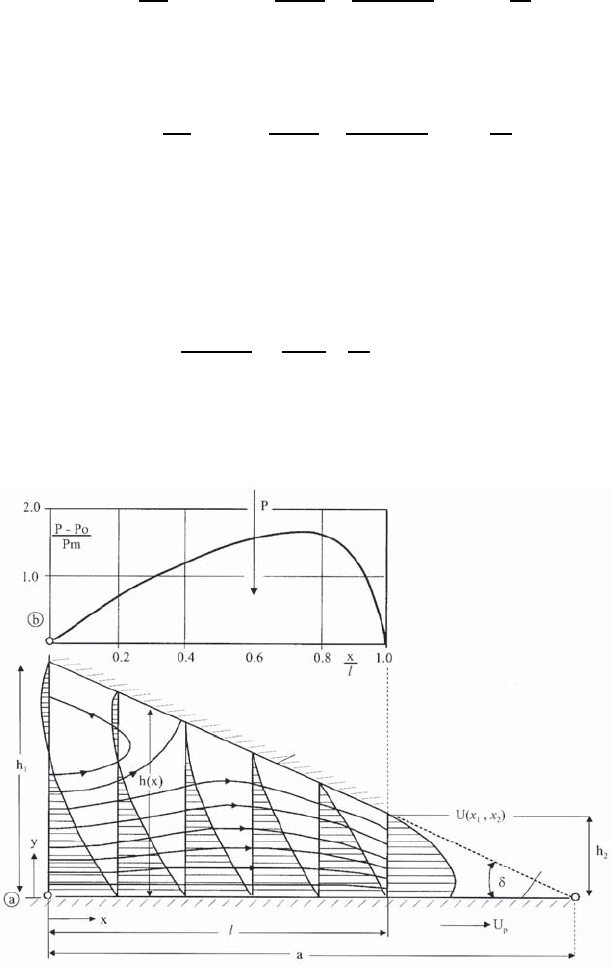
The flow lines developing in the film flow are shown in Fig. 15.3, to-
gether with the plotted local velocity profiles. The profiles result from (15.30),
including (15.38) for the computations. The following was introduced:
ρU
2
P
/l
µU
P
/h
2
=
ρU
P
l
µ
h
2
l
2
1. (15.43)
The above considerations were carried out for plane flows, as the intention
of the derivations was to give an introduction into the theory of tribological
flows. Flows in slide bearings usually have to be treated as rotating cylinder
Guide
surface
Upper plate
Lower plate
Fig. 15.3 Flow lines and velocity profile in a slide-bearing flow
438 15 Fluid Flows of Small Reynolds Numbers
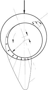
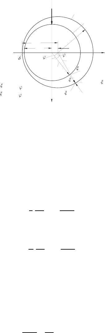
Fig. 15.4 Pressure distribution in rotating slide
bearings
Velocity
distribution
Force
Pressure
P
e
R
i
U
i
flows with an eccentric bearing positioning of the inner cylinder, relative
to the outer one. This bearing case is plotted in Fig. 15.4, which shows the
developing pressure distribution due to rotation. It is characteristic for this
kind of flow that the direction of the pressure maximum is not situated in the
direction of the load. Details of this flow are treated in the following chapter.
They represent the basis for understanding the fluid-mechanical functioning
of rotating slide bearings.
15.4 Theory of Lubrication in Roller Bearings
A roller bearing comprises a nonrotating bearing and a pivot rotating at
angular velocity ω. The practically employed double-cylinder arrangement is
shown in Fig. 15.5, with the following approximations being valid:
R
1
+ h ≈ R
2
+ e cos ϕ,
R
2
= R
1
+ e + δ,
h ≈ δ + e(1 + cos ϕ).
The solution of the equations for the fluid motion, which is important for the
lubrication flow in slide bearings, i.e. the rotating fluid motion which develops
between pivot and bearing, probably represents the technically most impor-
tant application of Stokes’ equations. Due to the resultant fluid movement
in a thin film, well-known bearing friction laws result which differ drastically
to those for dry friction laws. To demonstrate this, the motion of the inner
cylinder (pivot) having a radius r = R
1
is considered, which rotates at an-
gular velocity ω, while the outer cylinder (bearing), having the radius R
2
,
is at rest. The internal rotating cylinder thus has a circumferential velocity
U = R
1
ω. From the representation in Fig. 15.5, one can establish that the
position of the bearing can be given as r = R
1
+ h.Hereh = δ + e(1 + cos ϕ).
15.4 Theory of Lubrication in Roller Bearings 439
e
R
R =
Radius of pivot
1
2
x
1
x
= 0 : U = U
= h : U = 0
R
2
R
1
= h
r = R +
= 0
e cos
R
R =
Radius of bearing
2
1
Pivot
Bearing
Fig. 15.5 Bearing-pivot arrangement for considered roller bearing
These relationships hold with sufficient precision for the considerations car-
ried out. In this section, δ is the film thickness of the lubrication fluid existing
at ϕ = 180
◦
and e the eccentricity of the center point of the bearing with
regard to the position of the center point of the pivot.
On introducing into the considerations that the film thickness δ is very
small with respect to the radius of the pivot, i.e. δ/R
1
1 holds, then one can
show that ∂U
ϕ
/∂r 1/r∂U
ϕ
/∂ϕ holds. Order of magnitude considerations
of the remaining terms in the momentum equation (5.115) demonstrate that
the following differential equation can be employed for the treatment of film
flows in roller bearings:
1
r
∂P
∂ϕ
= µ
∂
2
U
ϕ
∂r
2
. (15.44)
As the r values appearing in the flow field of the film do not vary strongly,
the following approximation holds, because r ≈ R:
1
R
∂P
∂ϕ
= µ
∂
2
U
ϕ
∂r
2
. (15.45)
Due to this simplification, it is possible to treat the problem of roller bearings
in a way which comes close to that of the plane slide bearing.
Concerning the integration of the differential (15.45), one can proceed as
follows. The introduction of the variable ξ yields
r = R
1
+ ξ ; dr =dξ. (15.46)
Integration of (15.45) therefore yields:
U
ϕ
=
1
2R
1
µ
dP
dϕ
ξ
2
+ C
1
ξ + C
2
. (15.47)
440 15 Fluid Flows of Small Reynolds Numbers
With the boundary conditions:
ξ =0 : U
ϕ
= U and ξ = h : U
ϕ
= 0 (15.48)
C
1
and C
2
can be determined, so that the following relationship holds:
U
ϕ
=
1
2R
1
µ
∂P
∂ϕ
ξ (ξ − h)+
U(h − ξ)
h
. (15.49)
For the volume flow rate, one can derive:
˙v =
R+h
#
R
U
ϕ
dr =
h
#
0
U
ϕ
dξ = −
1
2R
1
µ
∂P
∂ϕ
h
3
6
+
Uh
2
. (15.50)
Due to the introduction of a mean film thickness h
0
with:
˙v = −
1
2R
1
µ
∂P
∂ϕ
h
3
6
+
Uh
2
=
Uh
0
2
(15.51)
and thus from (15.45), the following pressure gradient can be computed:
∂P
∂ϕ
=
6RµU(h − h
0
)
h
3
(15.52)
and by integration the pressure distribution results:
P (ϕ)=P(0) + 6R
1
µU
⎡
⎣
ϕ
#
0
dϕ
h
2
− h
0
ϕ
#
0
dϕ
h
3
⎤
⎦
. (15.53)
With h ≈ δ + e(1 + cos ϕ) from Fig. 15.5, the following results:
h(ϕ)=e
δ
e
+1+cosϕ
= e (α +cosϕ) . (15.54)
Because P(2π)=P(0) = P
0
, according to (15.53) it must hold that:
2π
#
0
dϕ
h
2
= h
0
2π
#
0
dϕ
h
3
−→ h
0
=
'
2π
0
dϕ
h
2
'
2π
0
dϕ
f
3
. (15.55)
Considering:
2π
#
0
dϕ
(α +cosϕ)
h
=2
π
#
0
dϕ
(α +cosϕ)
h
(15.56)