Durst F. Fluid Mechanics: An Introduction to the Theory of Fluid Flows
Подождите немного. Документ загружается.

13.4 Plane Fluid Flow Between Plates 369
The force exerted on one side of the material to be coated in the slot can be
computed as follows:
F = BLτ
w
= −BLµ
dU
1
dx
2
= BLµ
U
0
D
. (13.40)
Finally, attention is drawn to the fact that the Couette flow is characterized
in such a way that in the entire flow field, the same molecular-dependent
momentum transport takes place at every location x
2
. For this reason the
Couette flow is often sought as a fluid flow for basic investigations, in order to
examine experimentally the influence of the shear stresses on fluid properties
of non-Newtonian fluids.
13.4 Plane Fluid Flow Between Plates
In Sect. 13.2, the generally valid basic equation for an incompressible (ρ =
constant), stationary and one-dimensional (fully developed) flow of a New-
tonian medium with constant viscosity (µ = constant) was derived. This
equation:
dΠ
dx
1
= µ
d
2
U
1
dx
2
2
+ ρg
1
(13.41)
holds also for the fluid flow between two infinitely long plane plates arranged
as shown in Fig. 13.3.
This figure shows two plates which are placed at a distances x
2
=+D
and x
2
= −D with the planes in x
3
= constant as surfaces located in a
Cartesian coordinate system. The fluid flow takes place between these two
plates and the flow velocity is equal to zero at the surfaces of the plates
(non-slip condition).
If one selects x
1
perpendicular to the gravity field, then (13.41) reduces to
the following form:
dΠ
dx
1
= µ
d
2
U
1
dx
2
2
. (13.42)
Fig. 13.3 Fully developed fluid flow between two plane and parallel plates
370 13 Incompressible Fluid Flows
This relationship expresses the fact that the motion of the flow between
the plates is caused by an imposed external pressure gradient. Pressure and
viscosity forces for these kinds of flows are in equilibrium for a fluid element.
As the pressure distribution dΠ/dx
1
can only be a function of x
1
(see
Sect. 13.2) and the right-hand side of the above equation depends only on x
2
,
i.e. U
1
(x
2
), dΠ/ dx
1
has to be constant for the flow between parallel plates.
Thus, we have a simple linear differential equation of second order which has
to be solved to obtain the velocity profile of the plane channel flow.
By a first integration one obtains:
dU
1
dx
2
=
1
µ
dΠ
dx
1
x
2
+ C
1
. (13.43)
This differential equation has as a general solution obtained by a second
integration:
U
1
=
1
2µ
dΠ
dx
1
x
2
2
+ C
1
x
2
+ C
2
. (13.44)
Due to the following boundary conditions:
x
2
=+D −→ U
1
=0=
1
2µ
dΠ
dx
1
D
2
+ C
1
D + C
2
, (13.45)
x
2
= −D −→ U
1
=0=
1
2µ
dΠ
dx
1
D
2
− C
1
D + C
2
(13.46)
one obtains the values for the integration constants:
C
1
=0 and C
2
= −
1
2µ
dΠ
dx
1
D
2
(13.47)
and thus the solution for the velocity distribution between the plates can be
given as follows:
U
1
= −
1
2µ
dΠ
dx
1
D
2
1 −
x
2
D
2
for − D ≤ x ≤ D. (13.48)
This relationship for the flow velocity U
1
shows that the velocity profile be-
tween the plates represents a parabola. The maximum velocity is at the center
of the channel. At the surfaces of both the plates the flow velocity is zero and
in the entire flow field U
1
is positive, because for the flow region |x
2
|≤D
holds and, hence, [1 − (x
2
/D)
2
] is always positive. However, the pressure
gradient in the x
1
direction decreases, i.e. the resultant pressure gradient is
negative, so that the velocity U
1
in the x
1
direction, according to (13.43), is
positive. Assuming that the plates in the x
3
direction have a width B,the
volumetric flow rate per unit time can be computed for the flow in Fig. 13.3
as follows:
13.4 Plane Fluid Flow Between Plates 371
˙
Q =2B
D
#
0
U
1
dx
2
=
2B
2µ
dΠ
dx
1
1
3
x
3
2
− D
2
x
2
D
0
. (13.49)
Thus the following results are valid for the flow rate
˙
Q and the mean velocity:
˙
Q = −
B
µ
dΠ
dx
1
2
3
D
3
−→
˜
U =
˙
Q
2DB
= −
1
3µ
dΠ
dx
1
D
2
. (13.50)
For the velocity U
max
one can compute
U
max
= U(x
2
=0)=−
1
2µ
dΠ
dx
1
D
2
;
˜
U =
2
3
U
max
. (13.51)
From
˙
Q one obtains for the pressure gradient
dΠ
dx
1
=
∆P
∆L
=
3µ
˙
Q
2BD
3
. (13.52)
From this it can be seen that the pressure drop is linear and is directly pro-
portional to the dynamic viscosity and to the volume flow rate and inversely
proportional to the cube of half the channel height. The action of forces on
the plate due to the molecular momentum transport results from the product
of the shear stress at the wall τ
w
and the area of the plates
τ
w
= −µ
dU
1
dx
2
x
2
=x
w
, (13.53)
dU
1
dx
2
w
=
1
µ
dΠ
dx
1
(x
2
)
w
;(x
2
)
w
= D; τ
w
= −
dΠ
dx
1
D. (13.54)
The force acting on one of the plates having length L and width B is given
by
F = τ
w
A =
dΠ
dx
1
DLB. (13.55)
As a further quantity, which is often used in fluid mechanics, the friction
coefficient of the flow can be computed
c
f
=
τ
w
ρ
2
˜
U
2
=
τ
w
2D
µ
2
˜
U2D
µ/ρ
˜
U
=
1
Re
4Dτ
w
µ
˜
U
. (13.56)
With
τ
w
=
dΠ
dx
1
D and
˜
U =
˙
Q
2DB
=
1
3µ
dΠ
dx
1
D
2
, (13.57)
one obtains
c
f
=
12
Re
with Re =
˜
U2D
ν
. (13.58)
On plotting the friction coefficient as a function of the Reynolds number in
a diagram with double-logarithmic scales, one obtains a straight line with a
gradient of −1.
372 13 Incompressible Fluid Flows
13.5 Plane Film Flow on an Inclined Plate
In this section, fluid flows which are generally called film flows will be con-
sidered. They find applications in many fields of chemical engineering. Such
flows can be extremely complex, when the base plates of the flow show irreg-
ularities or waviness. To simplify the considerations to be carried out here,
only smooth surfaces are considered. In addition, the considerations are only
carried out for incompressible fluids with constant viscosity. Furthermore,
the assumption of two-dimensionality of the fluid flow is introduced into the
derivations and extended by the assumption of fully developed film flows fi-
nally yielding the one-dimensionality of the flow, so that the following basic
equation holds:
0=−
dΠ
dx
1
+ µ
d
2
U
1
dx
2
2
+ ρg
1
. (13.59)
In the examples shown in Fig. 13.4, the film motion is caused by the mass
forces occurring in the flow direction and not, as in the case of the plane
channel flow, by an externally imposed pressure gradient, i.e. for the film
flow the following holds for the pressure gradient:
dΠ
dx
1
=0, (13.60)
which finally results in the following simple basic equation for gravity-driven
film flows:
µ
d
2
U
1
dx
2
2
+ ρg
1
=0. (13.61)
In the case of film flows which are caused by mass forces on the fluid, the mass
and the viscous forces at a fluid element are in equilibrium. The diagram in
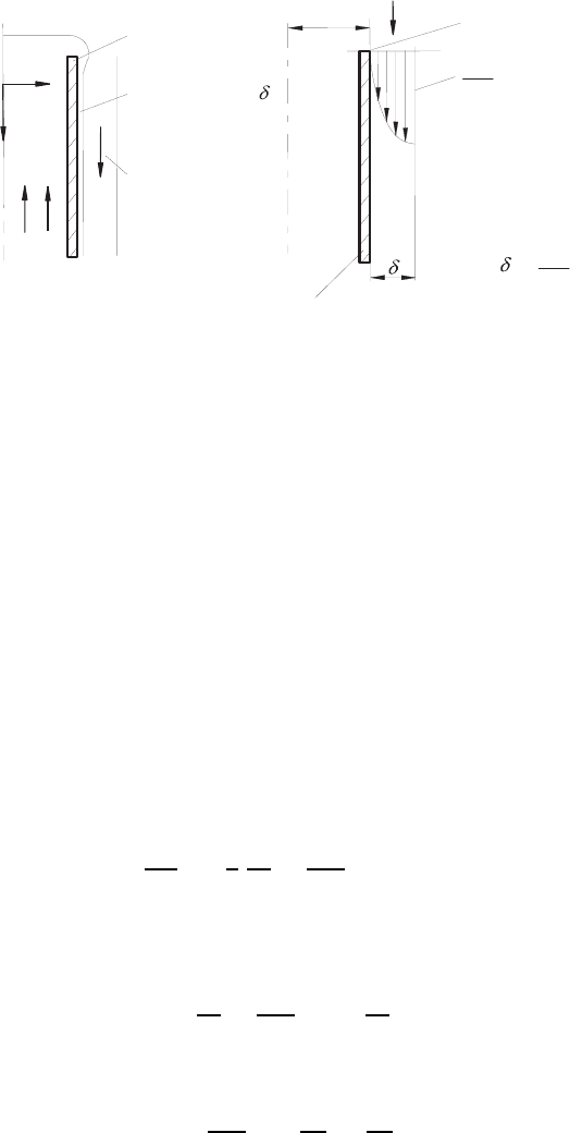
Fig. 13.4 shows a film flow which can be treated analytically as will be shown
later.
x
Free surface
of
film flow
U
1
x
1
2
Surface of
inclined wall
Angle of inclination
Fig. 13.4 A fluid film on a plane, inclined wall
13.5 Plane Film Flow on an Inclined Plate 373
Applied vacuum
Over flow
Temperature control
channels
Substrate
to be coated
Substrate carrying roller
Coating fluid
Coating of a single layer
Fig. 13.5 A film-coating system for a single layer
Fig. 13.6 A film-coating system for
several layers
Substrate to
be coated
Multi-layer coating
x
Applied vacuum
Over flow
Temperature control
channels
Substrate
carrying
roller
As an example of film flows that occur in the practice of chemical engi-
neering, different coating procedures are mentioned here which are applied in
industry in order to coat photographic papers and foils of all kinds. Current
coating procedures are presented in Figs. 13.5 and 13.6, which show that a
characteristic of the customary coating procedures is that the material used
for coating is supplied in fluid films. The fluid-volume flow supplied in the
films is, at a given geometry of the actual coating apparatus, controlled by
the supplied volume flow only. In this way, the supplied volume flow
˙
Q con-
trols the film thickness δ and through the latter it also controls the velocity
distribution in the wet film.
For the design and construction of coating systems of the kind shown in
Figs. 13.5 and 13.6, it is important to know the relationship δ(
˙
Q) The latter
can be found by solving the above differential equation for the boundary
conditions of the film flow. This needs then to be integrated to obtain the
374 13 Incompressible Fluid Flows
Liquid film
Curtain
Coated layer
U
0
Substrate
Coating dye
Fig. 13.7 Curtain coating procedure and equipment
volume flow rate (
˙
Q). In addition, the solution of the differential equation
also renders details of the velocity field that establishes itself in the fluid
film.
In the simple coating system represented in Fig. 13.7, the coating material
is supplied through a slot opening leading it on to a plane, inclined surface
where, due to gravitation, a film flow forms. The film falling downwards
impinges on to the substrate to be coated which, moved by rollers, carries
away the fluid film.
For the actual coating dye, after the fluid has reached the inclined flat
plate, a plane film flow develops which can be treated analytically. After a
short entrance length, the conditions for a stationary, fully developed film
flow exist. The component of the gravity acting in the x
1
direction is:
g
1
= g cos β. (13.62)
Thus, the differential equation describing the flow field reads:
d
2
U
1
dx
2
2
= −
ρg cos β
µ
. (13.63)
By a first integration one obtains from the above differential equation:
dU
1
dx
2
= −
ρg cos β
µ
x
2
+ C
1
(13.64)
and by another integration the final relationship for the velocity distribution
in the film results:
U
1
= −
ρg cos β
2µ
x
2
2
+ C
1
x
2
+ C
2
. (13.65)
As boundary conditions are available (see Fig. 13.4):
x
2
=0:
dU
1
dx
=0, i.e. C
1
= 0 because of the free surface, (13.66)
13.5 Plane Film Flow on an Inclined Plate 375
x
2
= −δ : U
1
=0, i.e. C
2
=
ρg cos β
2µ
δ
2
. (13.67)
Thus for the velocity distribution of the film, U
1
can be expressed as:
U
1
=
ρg cos βδ
2
2µ
1 −
x
2
δ
2
. (13.68)
This equation describes the parabolic velocity profile which is characteristic
for film flows with the maximum velocity being at the free surface of the film,
i.e. for the coordinate system chosen in Fig. 13.4 at the location x
2
=0.
When the velocity profile in the fluid film is known (see (13.68)), the
volume flow
˙
Q can be computed by the following integration, where B is the
width of the film perpendicular to the x
1
− x
2
plane:
˙
Q = B
0
#
−δ
U
1
dx
2
= B
ρg cos βδ
2
2µ
0
#
−δ
1 −
x
2
δ
2
dx
2
, (13.69)
˙
Q = B
ρg cos βδ
2
2µ
x
2
−
1
3δ
2
x
3
2
0
−δ
. (13.70)
From this,
˙
Q can be computed as:
˙
Q = B
ρg cos βδ
3
3µ
. (13.71)
The volume flow running in a fluid film is inversely proportional to the dy-
namic viscosity and directly proportional to the cubic power of the film
thickness. The mean velocity results as:
˜
U =
˙
Q
Bδ
=
ρg cos βδ
2
3µ
. (13.72)
When the force acting on the film carrying surface in the x
1
direction is of
interest, it can be computed for a surface having the dimensions L and B as
follows:
F
1
= τ
B
LB = −µ
dU
1
dx
2
x
2
=−δ
LB = −δLBρg cos β. (13.73)
This value corresponds to the component of the weight of the total film acting
in the x
1
direction over the length. This final result expresses that the film as
a whole adheres to the plate and thus the momentum transport to the wall
compensates the weight of the film.
In connection with the motion of the plane fluid film, the energy dissipation
in viscous fluids will be considered in more detail. In a fluid film, as shown
in Fig. 13.3, a fluid volume (LB dx
2
)havingthemass(ρLB dx
2
)isflowing
downwards, per unit time, over a distance U
1
cos β in the direction of the
gravitational acceleration. In this way, the following potential energy per
376 13 Incompressible Fluid Flows
unit time is set free:
d
˙
E
pot
= ρLB dx
2
U
1
cos βg. (13.74)
Hence the potential energy
˙
E
pot
for the entire fluid film results as:
˙
E
pot
=
0
#
−δ
ρLB
ρg cos βδ
2
2µ
1 −
x
2
δ
2
cos βg dx
2
, (13.75)
˙
E
pot
= LB
ρ
2
g
2
cos
2
βδ
2
2µ
x
2
−
x
3
2
3δ
2
0
−δ
, (13.76)
˙
E
pot
= LB
ρ
2
g
2
cos
2
βδ
3
3µ
. (13.77)
This energy, set free per unit time by moving in the direction of gravity
along the length L, dissipates due to the viscosity of the flow medium. The
dissipated energy E
diss
per unit time and unit volume for a fluid layer of
width 1 can be given as follows:
dE
diss
dV
= µ
dU
1
dx
2
2
= ρ
2
g
2
cos
2
βx
2
2
1
µ
. (13.78)
For the considered volume of the entire film, the dissipated energy per unit
time is computed by integration
˙
E
diss
= LB
ρ
2
g
2
cos
2
β
µ
0
#
−δ
x
2
2
dx
2
, (13.79)
˙
E
diss
= −LB
ρ
2
g
2
cos
2
β
3µ
δ
3
. (13.80)
Thus
˙
E
pot
+
˙
E
diss
= 0 holds, i.e. the total potential energy of the falling film
is dissipated due to the viscosity of the flowing fluid, i.e. potential energy is
converted into heat. Because of the generally very high heat capacity of fluids,
this means, e.g. for water, only a very small increase of the fluid temperature.
13.6 Axi-Symmetric Film Flow
In addition to the description of plane film flows in Sect. 13.5, fluid films that
develop on axi-symmetric surfaces are also of interest in chemical engineering.
As an example, a film is shown in Fig. 13.8 which flows down on the outside
of a cylindrical body. The volume flow needed for the stationary fluid film is
conveyed upwards in the inner space of the cylindrical body, flows outwards
13.6 Axi-Symmetric Film Flow 377
Solid wall
Film thickness
Air flow
Supplied liquid
r
z
R
U = 0
z
dU
z
dr
= 0
The boundary
conditions are:
U = 0
z
r R
r R+
=
=
dU
z
dr
= 0
:
:
Q
.
(a)
(b)
Solid wall
Fig. 13.8 (a) Falling film outside a cylinder. (b) Important quantities for the solution
of the differential equation for the velocity of the fluid film
at the upper edge and forms there, after a short development length, an axi-
symmetric, stationary fluid film which is fully developed in the flow directions.
The fluid volume running down in the film per unit time corresponds to the
volume flow transported upwards in the inner space of the cylinder.
Film producing systems, such as schematically indicated in Fig. 13.8 are
often employed in chemical engineering. The fluid film running downward has
a large surface area, when compared with its volume, which can be brought
in contact with the surrounding gas to be absorbed. The gassing takes place
over the entire contact surface of the fluid and goes on until the entire fluid
film is saturated.
After the film in Fig. 13.8 has moved a short development distance, it
takes on a fully developed state, i.e. the fluid mechanics of the film flow
can be described by the following differential equation for one-dimensional,
axi-symmetric flows of fluids with constant density and constant viscosity:
−
dΠ
dz
+ µ
1
r
d
dr
r
dU
z
dr
+ ρg
z
=0. (13.81)
The externally imposed pressure gradient ( dΠ/ dz) is zero for film flows,
so that with g
z
= g it holds that:
d
dr
r
dU
z
dr
= −
ρg
µ
r. (13.82)
After a first integration, one obtains:
dU
z
dr
= −
ρg
2µ
r +
C
1
r
(13.83)
378 13 Incompressible Fluid Flows
and after a second integration:
U
z
= −
ρg
4µ
r
2
+ C
1
ln r + C
2
. (13.84)
With the boundary conditions indicated in Fig. 13.8b, one obtains:
r = R; U
z
=0: 0=−
ρg
4µ
R
2
+ C
1
ln R + C
2
, (13.85)
r =(R + δ);
dU
z
dr
=0: 0=−
ρg
2µ
(R + δ)+C
1
1
(R + δ)
, (13.86)
C
1
=+
ρg
2µ
(R + δ)
2
, (13.87)
C
2
=+
ρg
4µ
R
2
−
ρg
2µ
(R + δ)
2
ln R. (13.88)
Thus the velocity profile can be expressed as:
U
z
=
ρg
4µ
R
2
3
1 −
r
R
2
+2
1+
δ
R
2
ln
r
R
4
. (13.89)
The fluid volume flowing in the film can be computed by the following
integration:
˙
Q =
R+δ
#
R
2πrU
z
dr =
πρg
2µ
R
2
R+δ
#
R
3
1 −
r
R
2
+2
1+
δ
R
2
ln
r
R
4
r dr,
˙
Q =
πρg
2µ
R
2
3
r
2
2
−
r
4
4R
2
+2
1+
δ
R
2
r
2
2
ln
r
R
−
1
2
4
R+δ
R
.
(13.90)
Thus for
˙
Q the following final relation results:
˙
Q =
πρgR
4
4µ
3
2
1+
δ
R
2
−
1
2
+
1+
δ
R
4
2ln
1+
δ
R
−
3
2
4
.
(13.91)
For the maximum velocity of the film flow, the following relationships hold:
(U
z
)
max
=
ρgR
2
4µ
3
1 −
R + δ
R
2
+2
1+
δ
R
2
ln
R + δ
R
4
, (13.92)
(U
z
)
max
=
ρgR
2
4µ
3
−2
δ
R
−
δ
R
2
+2
1+
δ
R
2
ln
1+
δ
R
4
. (13.93)
Finally, it should be mentioned with regard to film flows that they stay lam-
inar for small Reynolds numbers only, i.e. they behave for small Re-numbers
as indicated above. The above equations can only be applied to small film
thicknesses and fluids with relatively large kinematic viscosities. In chemical
engineering, a number of film flows occur which fulfil these requirements for
the existence of laminar flows.