Durst F. Fluid Mechanics: An Introduction to the Theory of Fluid Flows
Подождите немного. Документ загружается.

176 6 Hydrostatics and Aerostatics
forces. Although in practice this kind of bubble formation exists only to a
very limited extent, static bubble formation has a certain importance. As
it is analytically treatable, some important basic knowledge can be gained
from it which contributes to the general understanding of bubble formation,
also under dynamic conditions. Furthermore, knowledge is required on static
bubble formation in order to investigate the influences of the accelerative and
frictional forces in the case of the dynamic formation of bubbles.
The essential basic equations of static bubble formation can be derived
from the equilibrium conditions for the pressure forces at a free surface
element of the bubble.
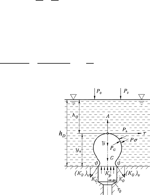
For the pressure equilibrium at an element, the following relationship of the
interface boundary surface holds, in accordance with Fig. 6.19. This means
that the gas pressure in the bubble p
G
has to be equal to the sum of the
hydrostatic pressure p
h
and the capillary pressure p
σ
:
p
G
= p
σ
+ p
h
=
1
R
1
+
1
R
2
σ + p
0
+ ρ
F
g (h
0
+ y) (6.70)
Here the gas pressure is
p
G
= p
G,0
+ ρ
G
gy (6.71)
When one considers the definition for the normalized radii of curvature, em-
ploying the Laplace constant, one obtains
¯
R
j
= R
j
/a,¯r = r/a,¯y = y/a.
Hence the following differential equation can be derived:
¯y
(1 + ¯y
2
)
3/2
+
¯y
¯r (1 + ¯y
2
)
1/2
=2
1
¯
R
0
− ¯y
(6.72)
Fig. 6.19 Equilibrium of forces at the
bubble interface (A, buoyancy force; G,
gravity; h
D
, distance of the nozzle from
the fluid surface; h
0
, distance of the bub-
ble vertex from the fluid surface; K
0
,
surface forces; K
P
, pressure forces; P
h
,
hydrostatic pressure; P
0
, atmospheric
pressure on the fluid surface)

6.3 Free Fluid Surfaces 177
By the substitution of
¯z =
¯y
1+¯y
2
=sinϑ (6.73)
the differential equation of second order can be replaced by a system of two
differential equations of first order:
d
d¯r
(¯r¯z)=2¯r
1
¯
R
0
− ¯y
(6.74)
d¯y
d¯r
=
¯z
√
1 − ¯z
2
=tanϑ (6.75)
which are used for integration. The desired bubble volume
¯
V is obtained in
dimensionless form by the following partial integration:
¯
V = π
¯y
#
0
¯r
2
d¯y = π¯r
2
¯y − 2π
¯y
#
0
¯r¯y d¯r (6.76)
and, with the use of (6.74), one obtains:
¯
V = π¯r
¯z +¯r
¯y −
1
¯
R
0
(6.77)
If one introduces again dimensional quantities, equation (6.77) can be written
as follows:
V
a
3
= π
r
a
¯z +
r
a
y
a
−
a
R
0
(6.78)
V = a
2
πr
¯z +
r
a
2
y −
a
2
R
0
(6.79)
With Laplace constant a and equation (6.73), the bubble volume V can
be written as c
V =
2σ
g (ρ
F
− ρ
G
)
πr
sin ϑ +
r
2σ
g (ρ
F
− ρ
G
)
y −
2σ
g (ρ
F
− ρ
G
) R
0
(6.80)
Equation (6.80) represents an integral property of the differential equa-
tion system (6.74) and (6.75) which was obtained from considerations of the
equilibrium of forces on a bubble surface element.
For the forces acting on a bubble as a whole (Fig. 6.19), the equilibrium
condition can be written in the form:
Vgρ
F
− Vgρ
G
+ πr
2
2σ
R
0
− g (ρ
F
− ρ
G
) y
=2πrσ sin ϑ (6.81)
178 6 Hydrostatics and Aerostatics
where the first two terms represent the buoyancy force and the weight of the
bubble and the third term on the left-hand side is the pressure force on the
bubble cross-section πr
2
at the height y. The surface forces are indicated on
the right-hand side. Equation (6.81) should be employed in cases where the
bubble volume is to be computed from the conditions of the equilibrium of
forces.
For the computation of the pressure changes during bubble formation, the
pressure in the bubble vertex can be expressed using equations (6.70) and
(6.71) and can be expressed as:
p
G,0
=
2σ
R
0
+ p
0
+
F
g (h
D
− y
s
) (6.82)
The pressure at the nozzle mouth varies according to (6.71) and (6.82) as
the following relationship shows:
p
G,D
=
2σ
R
0
+ p
0
+
F
gh
D
− g (
F
−
g
) y
s
(6.83)
Equation (6.83) can be written in dimensionless form:
∆¯p
D
=
1
2gσ (
F
−
G
)
[p
G,D
− p
0
−
F
gh
D
]=
1
R
0
− ¯y
s
(6.84)
Although the differential equation system (6.74) and (6.75) permits the
computation of all bubble forms of static bubble formation and by means of
equations (6.77) and (6.84), the corresponding bubble volumes and pressure
differences can be obtained as important quantities of the bubbles, the prob-
lem with regard to the single steps of bubble formation is not determined.
The solution of the equations only allows the computation of a one-parameter
set of bubble shapes, where the vertex radius R
0
is introduced into the deriva-
tions as a parameter. It does not permit one to predict in which order the
different values of the parameters are determined during bubble formation.
This has to be introduced into the considerations as additional information
in order to obtain a set of bubble forms that are generated in the course of
the bubble formation.
Theoretically, it is now possible to choose any finite set of quantities of R
0,i
values and to compute for these the corresponding bubble forms. Of practical
importance, however, is only one R
0,i
variation, which is given by most of
the experimental conditions. For these conditions, the set of R
0,i
values can
be selected as follows:
(a) All bubbles form above a nozzle with radius ¯r
D
.
(b)
¯
R
0,i
= ∞ is the starting shape of static bubble formation; the horizontal
position of the interface boundary surface above the nozzle is chosen to
start computations.
(c) All further vertex radii are selected according to the condition
¯
V
D
7
¯
R
0,i+1
8
≥
¯
V
D
[R
0,i
].

6.3 Free Fluid Surfaces 179
This means that the theoretical investigations are restricted to the bub-
ble formation which comes about through slow and continuous gas feeding
through nozzles having a radius ¯r
D
. Gas flows through the nozzles, and thus
a decrease in the bubble volume with the selected vertex radius, as (6.77)
or (6.79) would permit, are excluded from the consideration by the imposed
relationship (c). The consequent application of this relationship leads to the
formation of a maximum bubble volume. The same has to be considered to
be the volume of the bubble at the start of the separation process, i.e. the
lift-off occurs for
(d)
¯
V
A
=
!
¯
V
D
"
max
.
In the computations, the differential equation system (6.74) and (6.75)
was solved numerically for different vertex radii, considering the indicated
conditions, and thus a sequence of bubble forms was ascertained. The re-
sults of these computations are summarized in Figs. 6.20–6.25, which can be
consulted in order to understand the static bubble formation on nozzles in
liquids.
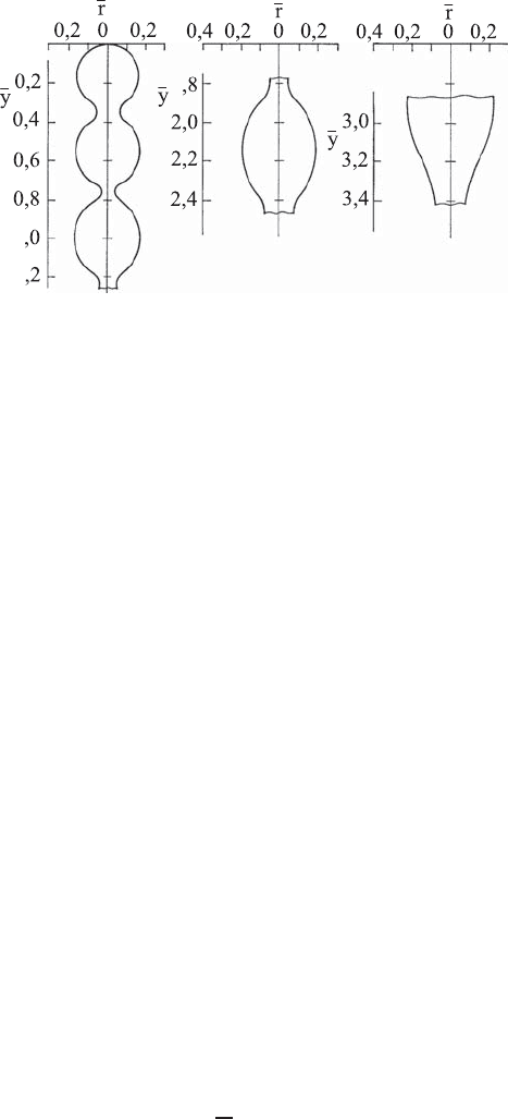
Figure 6.20 shows bubble forms that represent different stages of bubble
formation with slow gas feeding through nozzles. The results are reproduced
for ¯r
D
=0.4 and this corresponds to a nozzle radius of roughly r
D
≈ 1.6mm
in the case of air bubble formation in water.
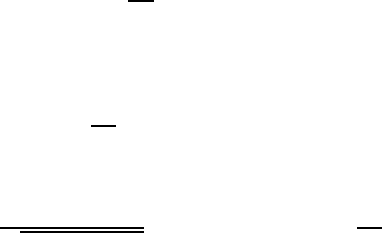
Figure 6.21 shows the change in the bubble volume during the formation
of gas bubbles on nozzles of different radii ¯r
D
, where the vertex radius
¯
R
0
was
chosen for designating the respective formation stage. From this diagram, it
can be inferred that a large part of the bubble forms at an almost constant
vertex radius and this is an important property for larger nozzle radii. For
r
−
D
Fig. 6.20 Bubble forms of the static bubble formation for ¯r
D
=0.4 computed
through integration of the equation system (6.74) and (6.75)
180 6 Hydrostatics and Aerostatics
Bubble volume
Vertex radius
Location of the maximum volume
limit of the bubble formation
Fig. 6.21 Bubble volume
¯
V as a function of the vertex radius
¯
R
0
for different nozzle
radii ¯r
D
Pressure difference
P
D
Limiting line
Location of the pressure maximum
of bubble formation
Vertex radius
Position of
pressure maximum
Fig. 6.22 Pressure difference ∆
¯
P
D
as a function of the vertex radius
¯
R
0
for different
nozzle radii ¯r
D
smaller nozzle radii, larger changes in the vertex radius are to be expected
during the formation of the gas bubbles. The vertex radius
¯
R
0
first decreases
and then increases again before the bubble separates from the nozzle.
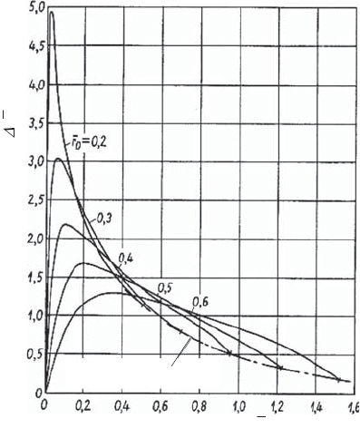
In Fig. 6.22, the pressure difference ∆
¯
P
D
as a function of the vertex ra-
dius
¯
R
0
is represented for different nozzle radii ¯r
D
. From this representation,
it can be gathered that, for static bubble formation on nozzles, initially a
continuous pressure increase at the nozzle mouth is necessary. After having
6.3 Free Fluid Surfaces 181
y
S
Location of the maximum
volume limit
Location of
maximum
vertex & location
from the nozzle
Vertex radius
R
D
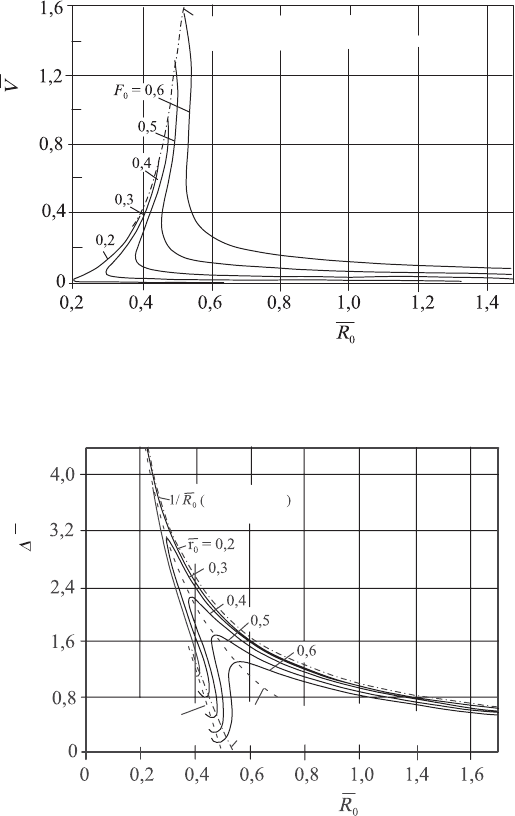
Fig. 6.23 Distance of the bubble vertex ¯y
s
from the nozzle top as a function of the
vertex radius
¯
R
0
for different nozzle radii ¯r
D
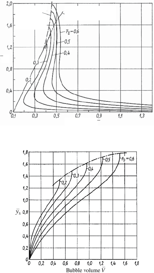
Fig. 6.24 Distance of the bubble vertex ¯y
s
from the nozzle top as a function of the
nozzle volume
¯
V for different nozzle radii ¯r
D
reached a maximum, distinct for all nozzle radii, the pressure decreases
again. This continuously increasing and then decreasing pressure change,
which is required for static bubble formation, makes it difficult to investigate
experimentally the static formation of gas bubbles on nozzles in liquids.
182 6 Hydrostatics and Aerostatics
Bubble volume
V
Location of (
V
D
)
max
Pressure difference
P
D
Fig. 6.25 Pressure difference ∆
¯
P
D
as a function of the nozzle volume for different
nozzle radii ¯r
D
Figures 6.23 and 6.24 show the change in the vertex distance from the noz-
zle during bubble formation for different nozzle radii. In Fig. 6.23, the vertex
radius was chosen for designating the respective stage of bubble formation,
whereas in Fig. 6.24 the bubble volume was employed.
Figure 6.25 represents the dimensionless pressure difference ∆
¯
P
D
as a func-
tion of the bubble volume for different nozzle radii ¯r
D
. The final points of the
different curves are given by the existence of a maximum bubble volume. As
can be seen from Fig. 6.22, the bubble of maximum volume above a nozzle
is not identical with that having a minimum pressure. However, the latter is
excluded from the possible bubble forms. This exclusion is due to the defi-
nition of static bubble formation given above. It is stated that a continuous
gas flow takes place through the nozzles towards the bubble.
For a general understanding of static bubble formation, two further facts
can be referred to:
(a) For the static bubble formation, a radius ¯r
D,gr
=0.648 exists which splits
up the static bubble formation into two different domains. For larger ¯r
D
bubbles form that differ in their shape from those shown in Fig. 6.20.
Theoretical investigations for nozzle radii ¯r
D
≥ ¯r
D,gr
were not carried
out here. They turned out to be unimportant for the introduction of
6.4 Aerostatics 183
1
1
1
Fig. 6.26 Bubble chains
¯
R
0
=1.60 ascertained from the differential equation system
(6.74) and (6.75)
the results intended here for a better understanding of the principles of
bubble formation.
(b) The differential equation system (6.74) and (6.75) allows the computa-
tion of bubbles, as shown in Fig. 6.26. These bubble columns were not
investigated further, as they are not in accordance with the above-stated
air flow through the nozzle for the examined static bubble formation.
Whereas static nozzle formation can theoretically be understood essen-
tially with simple mathematical means, there are considerable difficulties
with similar investigations of dynamic bubble formation. This is attributable
mainly to the fact that no coordinate system could be found in which dynamic
bubble formation could be described as a stationary process. Moreover, for
dynamic bubble formation, the pressure on an element of the interface bound-
ary surface is dependent on the fluid motions during the bubble formation and
thus is computable only by solving the non-stationary Navier–Stokes equa-
tion. This, however, is solvable only with difficulty and great computing effort
using numerical methods. Solutions of this fluid are not treated in this book.
6.4 Aerostatics
6.4.1 Pressure in the Atmosphere
Aerostatics differs from hydrostatics in the treatment of the properties of
the fluid. The partial differential equations for fluids at rest, derived from
the general Navier–Stokes equations, are applied along with the equation of
state for an ideal gas:
P
ρ
= RT (6.85)
rather than for an ideal liquid, ρ = constant.
184 6 Hydrostatics and Aerostatics
Hence the valid partial differential equations in aerostatics read:
∂P
∂x
j
= ρˆg
j
=
P
RT
ˆg
j
(6.86)
or written out for j =1,2,3:
∂P
∂x
1
=
P
RT
ˆg
1
,
∂P
∂x
2
=
P
RT
ˆg
2
,
∂P
∂x
3
=
P
RT
ˆg
3
(6.87)
This set of partial differential equations can now be employed for the
computation of the pressure distribution in such gases whose thermodynamic
state equation is given by (6.85). For most gases, and definitely for air under
atmospheric conditions, considerations can be carried out with the help of
this ideal gas equation. This will be made clear in the sections below with
the help of some examples.
When one considers the atmosphere of the Earth as consisting of a com-
pressible fluid at rest, whose thermodynamic state can be described by the
ideal gas equation (6.85), with a precision sufficient for the derivations at
issue, an approximate relationship between the height above the surface of
the Earth and the pressure of the atmosphere at a considered height H can
be derived, which in general is defined as the barometric height-pressure re-
lationship. In particular, the relationship known as Babinets approximation
equation will be derived here.
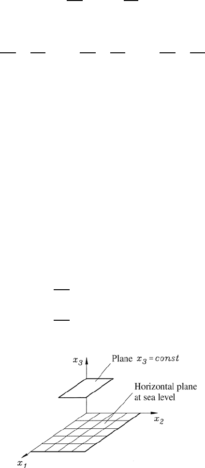
When one uses the coordinate system indicated in Fig. 6.27, in which the
plane x
1
,x
2
forms a horizontal area at the level of the sea surface, the partial
differential equations (6.87) can be written as follows:
∂P
∂x
1
=0; P = f (x
2
,x
3
)
∂P
∂x
2
=0; P = f (x
1
,x
3
)
(6.88)
Fig. 6.27 Coordinate system for the derivation of Babinet’s approximation equation
for the atmospheric pressure above the Earth’s surface
6.4 Aerostatics 185
i.e. P = f (x
3
) and thus the relation
∂P
∂x
3
−→
dP
dx
3
holds:
dP
dx
3
= −
P
RT
ˆg (6.89)
The differential equation which is to be solved can be written as follows:
dP
dx
3
= −
P
RT
ˆg
dP
P
= −
1
RT
ˆgdx
3
(6.90)
with the general solution:
ln
P
2
P
1
= −
1
R
#
(x
3
)
2
(x
3
)
1
ˆg
T
dx
3
(6.91)
The integral in the above equation can be solved only when it is known
how the gravitational acceleration g changes with height and when further
the temperature variation as a function of x
3
can be stated. For the gravita-
tional acceleration ˆg, it is known that it changes with the height x
3
,exactly
speaking, with the square of the distance from the center of the Earth. This
follows directly from Newton’s law of gravitation, when the influence of the ro-
tation of the Earth is neglected. When one designates the radius of the Earth
R and when g is the gravitational acceleration at sea level, the following
relation holds:
ˆg = g
1
1+
x
3
R
2
(6.92)
Taking into consideration the linear decrease in temperature with height
which often exists in the atmosphere, i.e. if one introduces:
T = T
0
(1 − αx
3
) (6.93)
one obtains the following final relation:
ln
P
H
P
0
= −
g
RT
0
H
#
0
dx
3
(1 − αx
3
)
1+
x
3
R
2
(6.94)
When one now imposes restrictions concerning the height above which the
above integration is to take place and when one chooses the height such that
the following relationship holds:
αx
3
1
x
3
R
1 (6.95)
one can obtain by series development of the terms in brackets:
ln
P
H
P
0
= −
g
RT
0
H
#
0
(1 + αx
3
+ ...)
1 −
2x
3
R
+ ...
dx
3
(6.96)