Czichos H., Saito T., Smith L.E. (Eds.) Handbook of Metrology and Testing
Подождите немного. Документ загружается.


928 Part D Materials Performance Testing
Intensity (arb. units)
8
6
4
2
10
0
1
Rel. scattering angle
Critical
angle
PP fiber, 20 μm
Pt wires, 100 μm
Cu wires, 25 μm
Quartz fibers, 10μm
Refraction theory
0 0.80.60.40.2
Fig. 16.72 The normalized shape of the angular intensity
distribution of cylindrical objects; PP – polypropylene
if normalized to the critical angle θ
C
of total reflection
(Fig. 16.72) defined by the refractive index θ
2
C
=2ε. The
intensity of the deflected x-rays becomes nearly zero at
the critical angle (Fig. 16.72), with a small contribution
from total reflection.
Applying a Kratky-type high-resolution small-angle
scattering camera with slit collimation a cross section of
10
−3
of the fiber diameter contributes to the detectable
intensity typically above 2 min of arc. Total reflection
of x-rays occurs as well but only 10
−6
of the cylin-
der diameter is involved and this is therefore negligible,
although planar surfaces may scatter all the primary in-
tensity if well aligned. Based on Snell’s Law the angular
intensity distribution of cylinders has been modeled and
X-ray
Slits
Scanning
Absorption
detector
Scattering
foil
Refraction
detector
Sample
source
PC
Fig. 16.73 Schematic of a SAXS instrumentation with a collimated
x-ray beam, sample manipulator, refraction detector for refracted
intensity, I
R
with sample or I
R
0
without sample, and an absorp-
tion detector for the attenuation intensity, I
A
or I
A
0
of the primary
beam
fitted to measurements on most different fibers, as il-
lustrated by Fig. 16.72. The refracted intensity I
∗
R
of
a cylinder (without absorption effects) can be expressed
by [16.51]
I
∗
R
(2θ
) =
J
0
2R
ε
sin
3
arctan
ε
θ
∼
=
J
0
2Rε
2
θ
3
.
(16.31)
J
0
is the irradiation density of the incident x-rays, R is
the cylinder radius and 2θ
=θ is the scattering angle.
In the case of spherical particles or pores I
∗
R
becomes
I
∗
R
(2θ
)
∼
=
J
0
2Rε
2
θ
4
. (16.32)
The conventional understanding of continuous small-
angle x-ray scattering (SAXS) is governed by the
interpretation of diffraction effects. Both the well-
known Guinier’s theory [16.53] for separated particles
and Porod’s theory [16.54] of densely packed col-
loids are based on diffraction of Rayleigh scattering.
Nevertheless Porod approximates the same angular in-
tensity decay as in (16.32). However both diffraction
approaches are about scattering objects two orders of
magnitude smaller.
16.5.2 Refraction Techniques Applying
X-ray Tubes
The SAXS instrumentation with an x-ray fine-structure
tube and a Kratky camera is relatively straightforward.
The camera needs an additional scattering foil for the
primary-beam attenuation measurement and a micro-
manipulation device for the sample (Fig. 16.73). For
practical measurements the refraction detector remains
at a fixed scattering angle 2θ
, so that the relative surface
density C of the specimen can be measured according
to [16.52]
C =
1
d
I
R
I
A
0
I
R
0
I
A
−1
, (16.33)
where I
R
and I
R
0
are measured by the refraction detec-
tor with and without sample, respectively, I
A
and I
A
0
are measured by the absorption detector, and where d
the wall thickness of a sample. Apart from the choice of
materials the relative surface density C depends solely
on the scattering angle and the radiation wavelength.
The absolute inner surface density (specific surface, sur-
face per unit volume) is determined by comparison with
Part D 16.5
Performance Control 16.5 Computed Tomography – Application to Composites and Microstructures 929
a known calibration standard at retained boundary con-
ditions (wavelength and scattering angle).
As well as the inner surface of pores and particles,
interfaces and cracks such as fiber debonding in com-
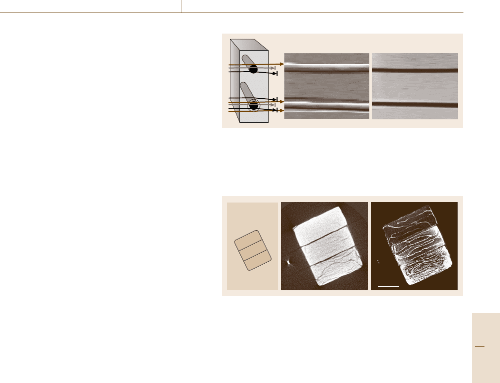
posites can also be determined. A model composite
has been made to demonstrate the refraction behavior
of a bonded and a debonded 140 μm sapphire fiber in
a polymer matrix (Fig. 16.74, left). Figure 16.74 (mid-
dle) shows the resulting intensity distribution of a two-
dimensional refraction scan of the model composite.
The upper ray crosses the bonded fiber–matrix interface,
causing a small amount of deflected intensity. At the
debonded fiber and at the matrix surfaces (lower ray)
many more x-rays are deflected, due to the larger dif-
ference of the refractive index against air. The polymer
channel is clearly separated from the fiber surface. For
comparison a mapping of I
A
yields the transmission to-
pograph containing only the absorption information of
the projected densities, like in conventional radiography
(Fig. 16.74, right). In the case of a real composite mater-
ial the much thinner fibers are not spatially resolved, but
the higher refraction signal of debonded fibers reveals
quantitatively the percentage of debonded fibers.
Beyond the capabilities for two-dimensional to-
pographs the set up of Fig. 16.73 can be employed for
conducting computed tomography of a transversal sec-
tion. This requires vertical linear scans and rotation of
the sample to gain multiple projections for the parallel-
beam reconstruction procedure. A section of a C/C
ceramic matrix composite (CMC) for high-temperature
applications is investigated to image the different crack
patterns developing during manufacture by pyrolysis.
The three samples (Fig. 16.75, left) are based on dif-
ferent phenolic resin carbon-fiber-reinforced polymer
(CFRP) green bodies of good, intermediate and bad
fiber/matrix bonding.
The absorption signals are reconstructed according
to the rules for parallel-beam filtered back-projection as
shownbyFig.16.75, center. The resulting transversal
sections reveal major cracks and homogeneous do-
mains.
The refraction and the absorption intensities per-
mit the reconstruction of the relative inner surface
density according to (16.33)(Fig.16.75, right) which
shows a significantly higher number and finer cracks.
Additionally the average intensity levels reveal the
quantitative crack density without resoling individual
cracks. These findings have proved for the first time
that the degree of fiber debonding is retained during
processing from the green state to high-temperature
treatment [16.55].
Refraction topograph Transmission topograph
Fig. 16.74 x-ray scanning topography; left: model composite of
polymer matrix and embedded bonded (top) and debonded (bottom)
140-μm sapphire fiber; middle: x-ray refraction topograph of C-
values resolving debonding spatially: an interface image, free from
absorption effects; right: absorption projection
Samples:
C/C-ceramic
matrix composite
of
1mm
bonding of
carbon-fibers
good
medium
bad
Fig. 16.75 x-ray computed tomography (CT) of carbon/carbon ce-
ramic matrix composite (C/C-CMC); left: sample arrangement,
middle: crack pattern by conventional (x-ray absorption) CT, right:
highly contrasted cracks by refraction computed tomography
16.5.3 3-D Synchrotron Refraction
Computed Tomography
2-D refraction CT by conventional x-ray tubes has dis-
advantages. It is limited to low x-ray energies from
characteristic Cu and Mo radiation and thus restricted
to low-density materials. The thickness of the investi-
gated layer is as large as 1 mm and the measurements
require over 10 h. To overcome these limitations 3-D
synchrotron refraction CT is employed. At the BAMline
at BESSY, Berlin the available monochromatic energy
ranges from 5 keV up to 60 keV. Further advantages
are the high photon flux, the selectable energy and the
highly parallel photon flux.
The experimental set up is sketched in Fig. 16.76
[16.56]. A parallel monochromatic beam (up to 60 keV)
at about 2% bandwidth is delivered by a double mul-
tilayer monochromator (DMM). At the experimental
stage a beam of several 10 mm
2
is reflected sequentially
by two Si(111) single crystals at their Bragg condition
for the chosen energy. An x-ray-sensitive CCD cam-
era of about 5 × 5 μm
2
resolution is placed behind the
Part D 16.5
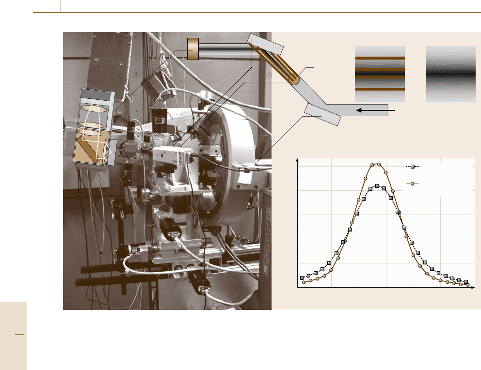
930 Part D Materials Performance Testing
OCD-
camera
2nd crystal
Specimen
Refraction Absorption
SR
1 st crystal
Rocking curve Si(111)
Intensity (arb. units)
80
60
40
20
100
0
4.8372 4.838
Bragg angle (°)
With specimen
FWHM: 1.8''
Without specimen
FWHM: 1.4''
4.8376
Fig. 16.76 Experimental setup for 3-D refraction CT at the synchrotron BAMline; left and top: goniometer and beam
components, right: rocking curve of the second Si(111) crystal (symmetric) with specimen (squares) and without
specimen (circles)
second crystal. A small inclination of the second crys-
tal varies the reflected intensity. The resulting rocking
curve widthis4×10
−4◦
full width at half-maximum
(FWHM)(Fig.16.76, circles). In contrast to the set up
for phase-contrast CT, the sample is positioned between
the two crystals. Thus the most-parallel beam traverses
the specimen and is attenuated according to the mass
distribution. Additionally, the beam is deflected due to
the refraction effect at all interfaces (Fig. 16.76,top
right). This leads to a broadening of the rocking curve
(Fig. 16.76, squares).
The presented investigation is performed on cylin-
drical tensile test samples of metal matrix composites
(MMCs, MTU Aero Engines, München). The most
advanced new material for aero engine compressor
components with high tensile strength at low spe-
cific weight is based on a Ti matrix embedding SiC
fibers. Their mechanical properties depend on the
fiber/matrix bonding and their high crack resistance
under high loads. Both characteristics require nonde-
structive characterization.
First a conventional 3-D CT investigation is car-
ried out employing a fine-focus x-ray tube. Figure 16.77
shows the density reconstruction of one out of 300
planes at 100-kV tube voltage and 5 × 5 × 5 μm
3
voxel resolution (720 projections, rotation about cylin-
der axes, Fourier-filtered back-projection). It shows
a transversal section of a low cycle fatigue (LCF)sam-
ple. Higher density appears brighter. The reinforcing
SiC fibers appear as dark discs with a slightly darker
(carbon) core. Solely in the selected plane of Fig. 16.77,
bottom, a dark shaded crack area appears due to reduced
absorption.
Synchrotron refraction computed tomography of
the same sample is performed at the BAMline with
the described set up at 50-keV radiation and 5 ×
5×5μm
3
detector voxel resolution (360 projections,
Fourier-filtered parallel-beam back-projection). The re-
construction of Fig. 16.78 images the same cross section
of the MMC LCF sample, but now the crack area
appears bright (color enhanced) and is much more de-
tailed. Also some debonded fibers can be identified by
Part D 16.5
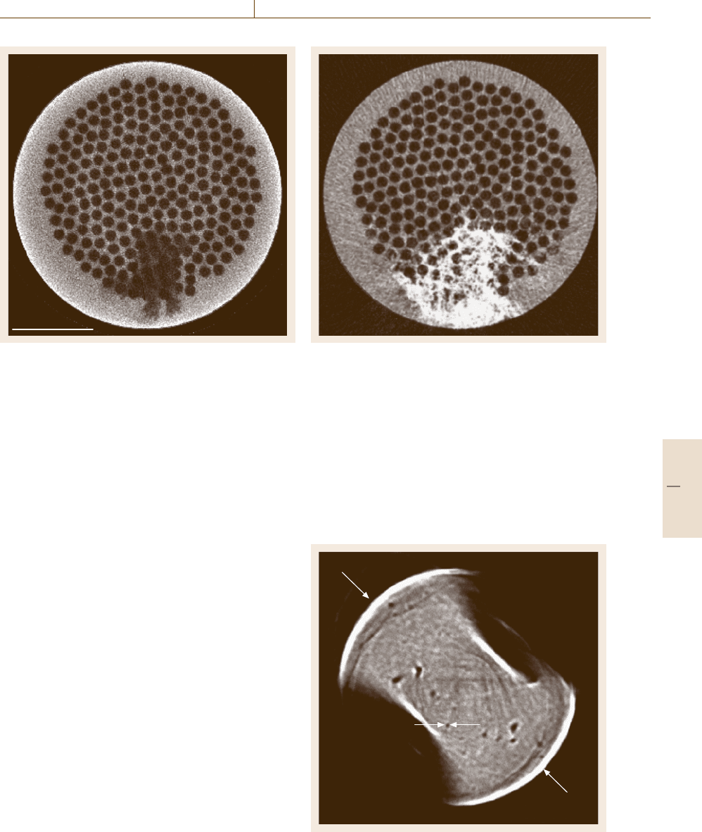
Performance Control 16.5 Computed Tomography – Application to Composites and Microstructures 931
1mm
Fig. 16.77 Conventional CT reconstruction of the absorp-
tion measurement on Ti-SiC MMC sample after fatigue;
fine-focus tube, 100-kV single-slice 3-D measurement
bright surrounding rings. In contrast to conventional
absorptive CT measurements the refraction contrast
provides crack indications in about 20% of the 300 re-
constructed slices of the sample [16.56].
The high inverse contrast (compared to Fig. 16.77)
originates from the rejection of deflected x-rays by the
second Si crystal in front of the CCD detector due to
refraction and total reflection interaction at the crack
boundaries. The refraction contrast is nearly indepen-
dent of the width of the cracks as it is a surface effect.
However, the contrast depends strongly on the angle of
the incident beam, which is only effective at (0±1)
◦
(plane crack). In the given set up, with both Si crystals
set to the top of their rocking curves, the image infor-
mation from absorption and refraction effects are both
present. If desired they can be separated by different
operation of the Si crystals.
Much higher spatial resolution can be achieved,
when the second crystal (Fig. 16.76) is replaced
by an asymmetric-cut crystal (Fankuchen cut). In
this the crystal surface is inclined against the re-
Fig. 16.79 3-D nano-refraction CT; reconstructed plane of
steel micro-drill from 19-keV projections; dark tubular
pores below 1 μm diameter; refraction contrast at outer
edges and around pores; magnification by Fankuchen-cut
single-crystal Si (at the center of the rocking curve)
Fig. 16.78 Synchrotron refraction CT of same slice
(Fig. 16.76); monochromatic 50-keV radiation, sample be-
tween two crystals at maximum reflection (after [16.56])
flecting lattice plane, resulting in a broadened exit
beam of up to 100× magnification. An example
of such nanometer-resolution refraction CT is given
by Fig. 16.79, which presents the reconstruction of
a horizontal section of a standing steel micro-
drill (100 μm diameter) using 19-keV radiation. Dark
tubular pores below 1 μm diameter, and refraction
1µm
100 µm
Part D 16.5
932 Part D Materials Performance Testing
contrast at the outer edges and around pores are
visible.
16.5.4 Conclusion
The presented findings demonstrate the high perfor-
mance of refraction CT for inner surfaces and inter-
faces, including microcracks. Even beyond the spatial
resolution of the reconstruction average crack densities
are determined. The techniques are expected to close
an essential gap in the spectrum of nondestructive tech-
niques for a better understanding of microstructures of
materials down to the nanometer scale and their behav-
ior under thermal and mechanical loads.
16.6 Structural Health Monitoring – Embedded Sensors
The final decade of the 20th century brought many
technological achievements, not only in regard to
the development of innovative and high-performance
materials but also in regard to advanced sensing tech-
niques. The embedment of sensors into materials or
structures opens up new possibilities to detect, e.g., the
presence of cracks or the onset of failure, to estimate
the extent of degradation, and to locate damaged zones.
This is the basic idea of structural health monitoring,
which has gained more importance within the last years.
This is an emerging technology that deals with the de-
velopment of techniques and systems for the continuous
monitoring, inspection and damage detection of struc-
tures. Today structural health monitoring can be found
in a wide area of industrial applications: starting from
A for aircraft and ending at Z for Zeppelin. Innova-
tive bridge design, higher safety requirements, extended
operation time, reduction of maintenance and inspec-
tion costs (e.g. less or no visual and NDT inspection)
are the driving forces for the usage of structural health
monitoring systems. The ultimate goal is to eliminate
current schedule-based inspection and replace it with
condition-based maintenance or repair.
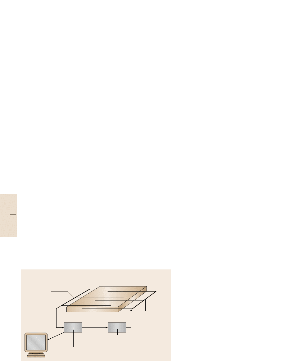
Sensor array
Mechanical structure
Actuator array
Control and drive network
Signal processing and data reduction
Display
Fig. 16.80 Conceptual diagram of a smart structure (after [16.57])
This chapter introduces the concept of structural
health monitoring, gives an overview of state-of-the-art
sensing techniques used for performance control and
condition monitoring, and reviews topical applications
from different industrial areas. Further detailed descrip-
tions of a wide range of practical applications can be
found e.g. in [16.58–63].
16.6.1 Basics
of Structural Health Monitoring
The basic idea of structural health monitoring (SHM)
can simply be described as the integration of a type
of sensing system that provides information on demand
about any significant change or damage occurring in an
aerospace, civil and mechanical engineering infrastruc-
ture [16.64]. The structural health monitoring process
involves the observation of a structure over time using
periodically sampled dynamic response measurements
from an array of sensors. The extraction of damage-
sensitive features from these measurements and the
statistical analysis of these features is then used to deter-
mine the current state of structural health. For long-term
structural health monitoring, the output of this process
is periodically updated information regarding the abil-
ity of the structure to perform its intended function in
light of the inevitable aging and degradation resulting
from operational environments. After extreme events,
such as earthquakes or blast loading, structural health
monitoring is used for rapid condition screening and
aims to provide, in near real time, reliable information
regarding the integrity of the structure [16.65]. During
operational use structural health monitoring attempts to
measure the inputs to and responses of a structure before
damage so that regression analysis can be used to pre-
dict the onset of damage and deterioration in structural
condition.
By combining the information of structural health
monitoring, current environmental and operational con-
Part D 16.6
Performance Control 16.6 Structural Health Monitoring – Embedded Sensors 933
ditions, previous component testing, nondestructive
testing, and numerical modeling, a prognosis is possi-
ble to estimate the remaining useful life of the structure.
By adding an actuator network and a related control
and drive system, the structure can be improved to
a so-called smart material or smart structure.Itisable
to monitor itself and/or its environment to respond to
changes in its conditions (Fig. 16.80) [16.57].
As mentioned before the detection and prediction
of onset of damage is the main target of structural
health monitoring. Damage in engineering structures is
defined as intentional or unintentional changes to the
material and/or functional or geometric properties of
these structures, including changes to the boundary con-
ditions and system connectivity, which adversely affect
the current or future performance of that structure. All
damage begins at the material level and, under appro-
priate loading scenarios, progresses to component- and
structure-level failure at various rates. Materials degra-
dation and failure can occur in different ways.
•
Gradually (e.g. fatigue, creep, corrosion, wear,
biodegradation, chemical degradation);
•
Suddenly and unpredictably (e.g. fracture, fiber
breakage, matrix cracking, fiber splitting, delamina-
tion, debonding).
All material degradation and failure precedes a change
of mechanical and/or chemico-physical characteristics
of the material. In this context mechanical character-
istics (e.g. elasticity, strength) and chemico-physical
characteristics (e.g. thermal expansion, temperature dis-
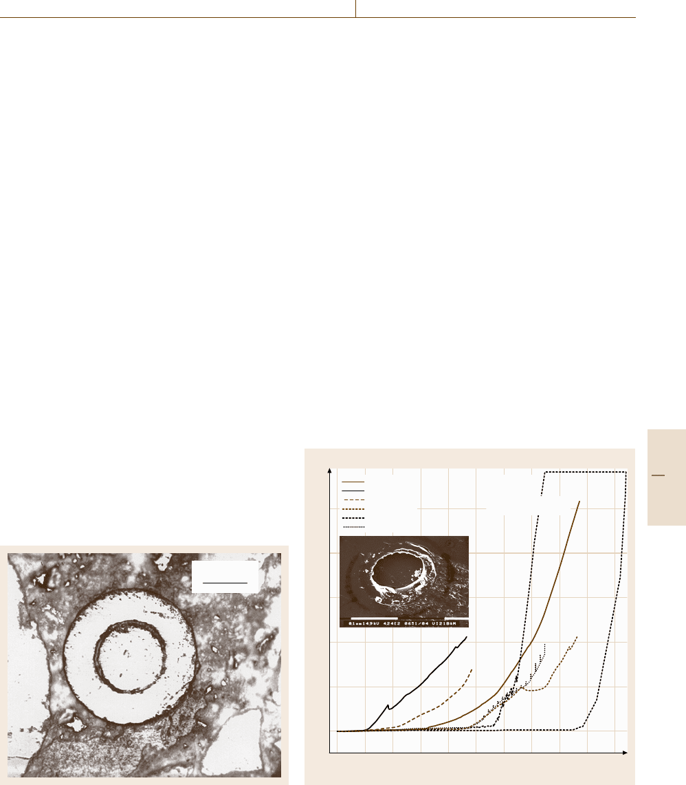
100 μm
Fig. 16.81 Cross section of a fiber-optic sensor embedded
into concrete (after [16.66])
tribution, humidity, oxidation or corrosion status) have
special meaning. These characteristics and/or associ-
ated auxiliary variables (such as, e.g., strain) must
be detected by means of physical sensor effects or
measurable quantities and converted into a useful out-
put signal. In all cases the sensing system must be
able to resolve the parameter of interest as a func-
tion of both position and time throughout the structure.
The spatial and temporal bandwidths that are required
to address these detection needs must be adapted to
the special requirements of the structure being moni-
tored.
Sensing capabilities can be given to materials or
structures by externally attaching sensors or incorpo-
rating them within the material or structure during
manufacturing. In the first place the incorporation of
the sensing system must be in compatibility with the
material structure. This means that the functional char-
acteristics and performance of the material may not be
impaired by the sensor integration. The embedding of
piezoelectric sensors into fiber-reinforced composites or
of fiber-optic sensors into concrete are typical exam-
ples for such a way of integration (Fig. 16.81). On the
other hand the sensor must be robust enough to survive
the manufacturing process (e.g. high temperatures dur-
ing curing process), withstand chemical attacks from
F (N)
2
1.5
1
0.5
2.5
du(26)iaaka.009
14.10.2004
Probe G
Ind. ca 95 μm
Thickness ca. 220 μm
du(26)iaaka.010
du(26)iaaka.011
du(26)iaaka.012
du(26)iaaka.023
du(26)iaaka.026
8070605040302010090
x (μm)
–10
0
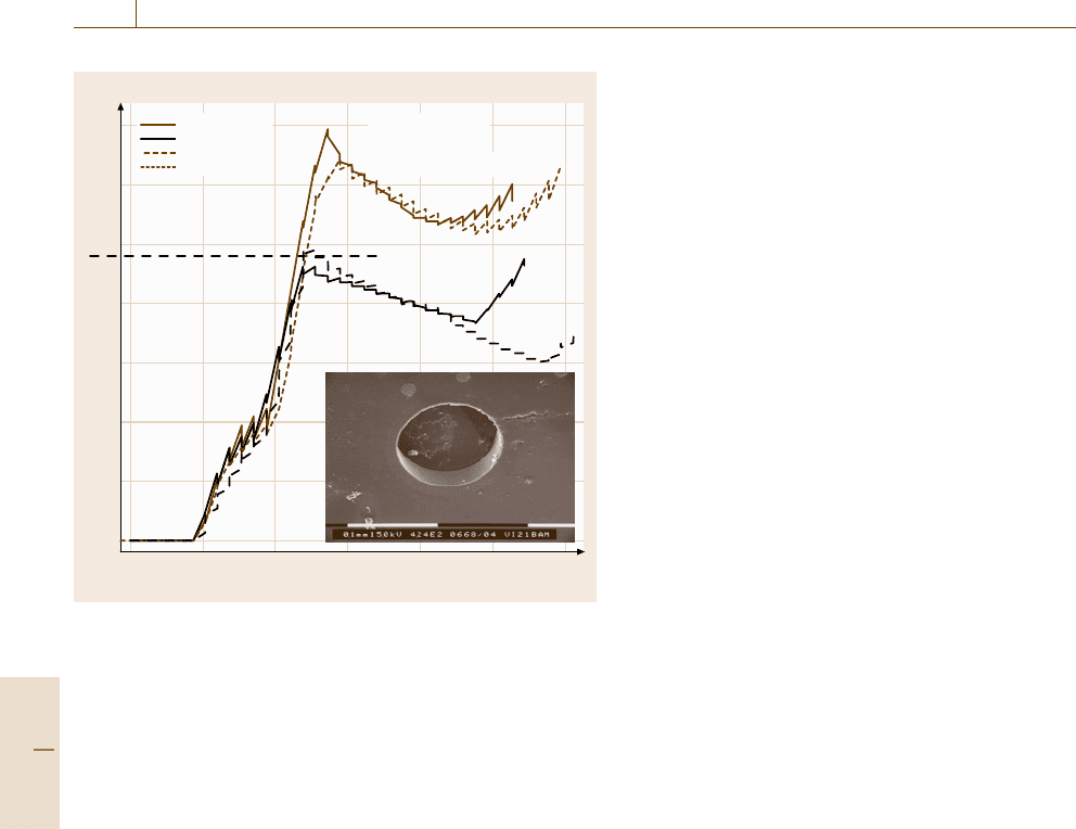
Fig. 16.82 Strain transfer of a two-layer coated fiber measured by
indentation testing (after [16.67])
Part D 16.6
934 Part D Materials Performance Testing
F (N)
F
max
1
0.75
0.5
0.25
1.25
1.5
1.75
du(26)iaaka.027
14.10.2004
Probe C
Ind. ca 95 μm
Thickness ca. 220 μm
du(26)iaaka.028
du(26)iaaka.029
du(26)iaaka.030
50403020100
x (μm)
–10
0
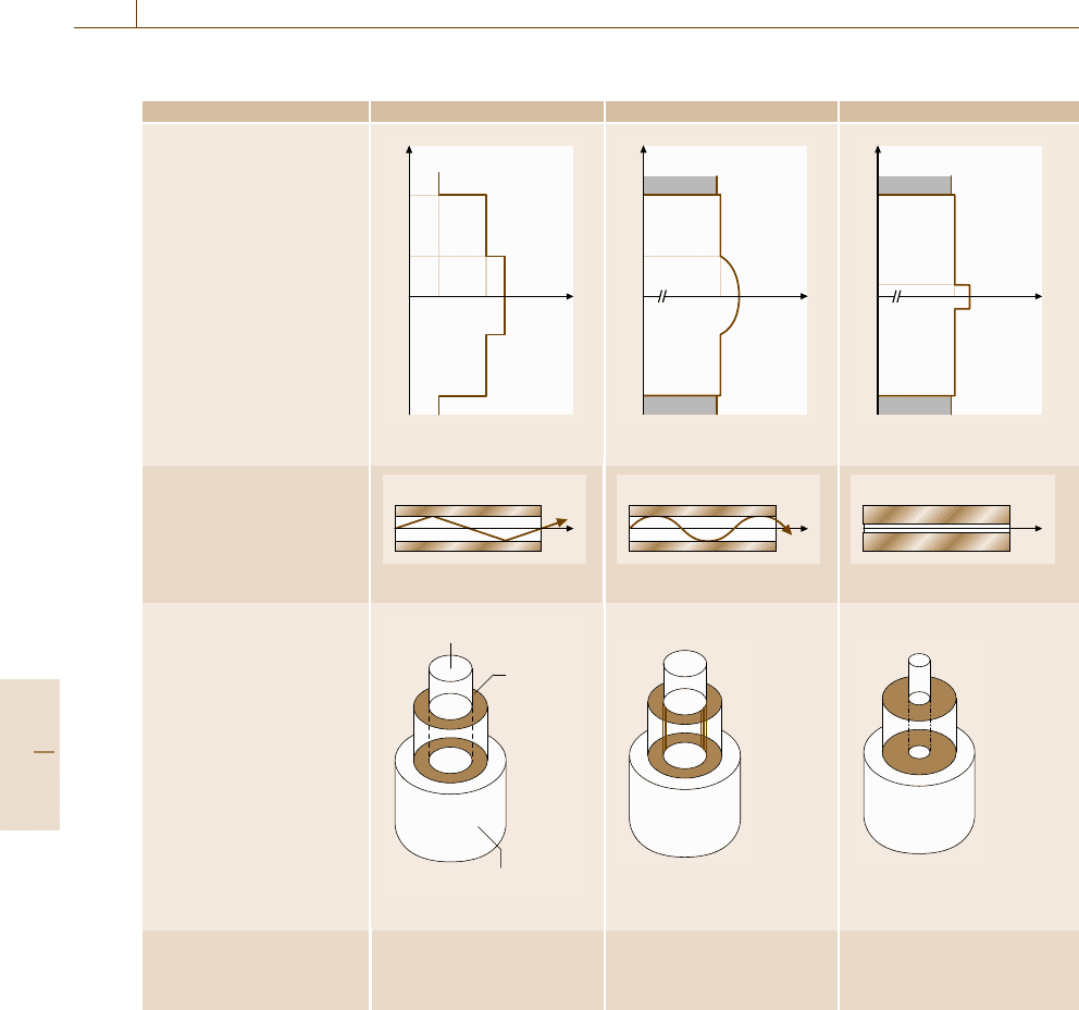
Fig. 16.83 Strain transfer of a polyimide-coated fiber measured by
indentation testing (after [16.67])
the material (e.g. very high pH environment in con-
crete), and withstand extreme mechanical loads (e.g.
highly elastic behavior of plastics) (Figs.16.82 and
16.83).
A wide range of physical sensor effects can be
used to detect changes of mechanical and/or chemico-
physical characteristics of a material. Preferably elec-
trical (e.g. piezoelectric materials) or optical sensing
effects (e.g. optical fibers) are used. Table 16.6 gives an
overview about common sensor effects, which are used
today for smart materials or structures.
To monitor a complete structure or a part of mater-
ial, different architectures of sensor arrangement can be
used. Basically the following variations are of practical
interest [16.57].
•
A point sensor is one that monitors a particular pa-
rameter at a closely confined point defined by the
effective cross-sectional area of the sensor element.
In principle, the point sensor only sees a sample of
the measurand at one particular point.
•
An integrating sensor is one that takes an aver-
age value of a particular measurand over an area
or length that is comparable to the area or length
of the structure being monitored. Integrating sensors
are sometimes spatially weighted (e.g. by variation
of sensitivity) to ensure that they are sensitized to
particular spatial distributions and not others.
•
A distributed sensor is capable of evaluating the
parameter of interest as a function of position
throughout the geometry of the sensor element. The
ability to perform distributed measurements is par-
ticularly important in structural health monitoring
since it enables the derivation of the measurand at
a large number of points throughout the structure
using a single interrogation port and thereby elimi-
nates the need for complex wiring harnesses.
•
A multiplexed sensor system is one that combines
a number of point, integrating, or distributed sensors
into a complex system. It could go through an elec-
tronic interface and use techniques derived from the
field. It can also be implemented at the sensor tech-
nology level. Here the multiplexing may be effected
on the measurand subcarrier.
•
A quasi-distributed sensor system combines a num-
ber of integrating sensors into a single system that
is multiplexed in the measurand carrier domain.
Finally the role of signal processing in structural
health monitoring should not be understated. Signal-
processing procedures can be divided into basic and
advanced methods [16.65]. A typical basic procedure is
data normalization. Data normalization is a procedure
to normalize data sets so that signal changes caused by
operational and environmental variations of the struc-
ture can be separated from structural changes of interest,
such as structural or material deterioration or degrada-
tion.
The purpose of data fusion is to integrate data from
a multitude of sensors with the objective of making
a more robust and confident decision than is possible
with any one sensor alone. In many cases, data fusion
is performed in an unsophisticated manner, as when
one examines relative information between various sen-
sors. At other times, such as those provided by artificial
neural networks, complex analyses of information from
sensor arrays are used in the data-fusion process.
Data cleansing is the process of selectively choos-
ing data to accept for, or reject from, the feature
selection process. The data-cleansing process is usu-
ally based on knowledge gained by individuals directly
involved with the data acquisition.
Feature extraction is the process of identifying
damage-sensitive properties, derived from the meas-
ured vibration response, which allows one to distinguish
between the undamaged and damaged structure. The
Part D 16.6

Performance Control 16.6 Structural Health Monitoring – Embedded Sensors 935
Table 16.6 Typical sensor effects to detect material degradation and failure
Material characteristics/ Sensor effects
measurand Electrical signals Optical signals
Mechanical:
• Strain
• Displacement
• Vibration
• Acceleration
• Force
• Pressure
• Piezoelectric effect
• Piezoresistive effect
• Change of resistance
• Change of
- Transmission
- Wavelength
-Phase
-Timeofflight
- Brillouin scattering
Chemico-physical:
• Temperature
• Humidity
• pH value
• O
2
concentration
• Heat flow
• Thermo resistance
• Thermoelectric effect
• Chemical resistance
• Conductivity
• Fluorescence
• Change of
− Transmission
− Wavelength
− Phase
− Raman scattering
− Brillouin scattering
best features for damage detection are typically appli-
cation specific. Numerous features are often identified
for a structure and assembled into a feature vector. In
general, a low-dimensional feature vector is desirable.
It is also desirable to obtain many samples of the fea-
ture vectors. There are no restrictions on the types or
combinations of data contained in the feature vector.
A variety of methods is employed to identify features
for damage detection. Past experience with measured
data from a structure, particularly if damaging events
have been previously observed for that structure, is
often the basis for feature selection. Numerical simu-
lation of the damaged structure’s response to postulated
inputs is another means of identifying features. The ap-
plication of artificial flaws, similar to those expected
in actual operating conditions, to laboratory specimens
can identify parameters that are sensitive to the ex-
pected damage. Damage-accumulation testing, during
which structural components of the system under study
are subjected to a realistic loading, can also be used
to identify appropriate features. Fitting linear or non-
linear, physical-based, or non-physical-based models of
the structural response to measured data can also help
identify damage-sensitive features.
Statistical model development is concerned with the
implementation of the algorithms that operate on the
extracted features to quantify the damage state of the
structure. The algorithms used in statistical-model de-
velopment usually fall into three categories. When data
are available from both the undamaged and damaged
structure, the statistical pattern-recognition algorithms
fall into the general classification referred to as su-
pervised learning. Group classification and regression
analysis are supervised learning algorithms. Unsuper-
vised learning refers to the class of algorithms that are
applied to data not containing examples from the dam-
aged structure.
The damage state of a structure can be described
as a five-step process [16.68]. The damage state is de-
scribed by answering the following questions.
1. Is there damage in the structure (existence)?
2. Where is the damage in the structure (location)?
3. What kind of damage is present (type)?
4. How severe is the damage (extent)?
5. How much useful life remains (prognosis)?
Answers to these questions in the order presented rep-
resent increasing knowledge of the damage state. The
statistical models are used to answer these questions in
an unambiguous and quantifiable manner.
16.6.2 Fiber-Optic Sensing Techniques
Basics
Basic element of a fiber-optic sensor is a thin optical
fiber made of a highly transparent glass or plastic (poly-
meric) material. The optical fiber consists of a core
having a refractive index n
core
and a surrounding
cladding having a refractive index n
cladd
.Insuchafiber
the propagation of light can be explained by different
models. The models are based on some fundamental
postulations and have certain limits of application. Ray
optics explains the kinematics of propagation. Wave op-
tics explains diffraction and interference phenomena.
Electromagnetic optics makes possible an exact anal-
ysis of the phenomena of classic optics, including the
effect of energy at the interfaces. Finally quantum optics
Part D 16.6
936 Part D Materials Performance Testing
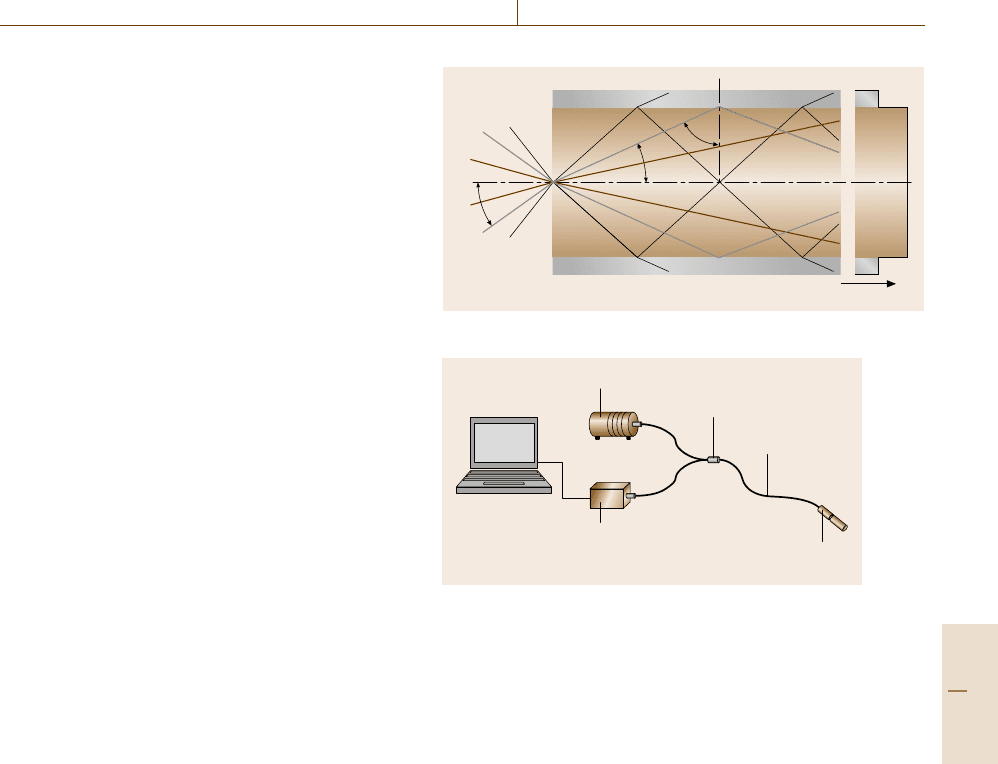
Table 16.7 Overview of most common types of silica optical fibers used for sensors
Fiber type Multimode step index Multimode graded index Single-mode step index
Refractive-index profile
r
b
a
1 n
2
n
1
n
r
b
a
1 n
2
n
1
n
r
b
a
n
2
n
1
n
Light propagation (schematic)
Beam is reflected
Beam is refracted
Beam is guided
Geometry
Core (n
1
)
Cladding
(n
2
)
Protective coating
Typical diameter Core: 50 μm
Cladding: 125 μm
Coating: 140 μm
to 250 μm
Core: 50 μm
Cladding: 125 μm
Coating: 140 μm
to 250 μm
Core: 6 μm (870 nm)
9 μm (1300 nm)
Cladding: 125 μm
Coating: 140–250 μm
explains all the known optical phenomena, including
interaction of light with matter. In this section the ex-
planations are limited to ray and wave optics, because
they allow a simple and practical understanding of fiber
optic sensing techniques. A comprehensive and detailed
introduction to all models (including Maxwell’s equa-
tions) can be found in [16.69,70].
Based on ray optics, light propagation in an opti-
cal fiber can be understood as follows. When light is
launched into one end of the fiber and n
core
> n
cladd
is true, it propagates along the fiber to the other end
corresponding to the physical effect of total internal re-
flection. Only light that is launched for 0 <Θ<Θ
max
can be guided along the fiber (assuming that Θ
max
is
the maximum value of the range of the accepted an-
gles Θ)(Fig.16.84). It is continuously reflected at the
interface between the core and the cladding; the criti-
cal angle α
max
must not be exceeded. Light that strike
the end face of the fiber at an angle greater than Θ
max
is no longer completely reflected at the core/cladding
Part D 16.6
Performance Control 16.6 Structural Health Monitoring – Embedded Sensors 937
boundary; instead it is partly refracted into the cladding
so that it is no longer completely available for further
propagation.
The properties of light guidance through a fiber are
governed largely by the profile of the refractive index
of the core and cladding. In a step-index-profile fiber
the refractive index is constant across the entire cross
section of the core and cladding (Table 16.7) while the
light rays propagate along straight lines in the core and
are completely reflected at the core/cladding bound-
ary. The individual light rays cover different distances,
so that there are considerable differences in their re-
spective transit times. This is called a multimode fiber.
Very small core diameters (< 10 μm) allow only one
mode to travel through the fiber (called single-mode
fibers). Fibers with a graded-index profile are made up
of a core having a radius-dependent refractive index and
a cladding with a constant refractive index. Those rays
converging in the center travel a shorter distance, but
because of the higher refractive index there, they travel
at a lower speed. On the other hand, the smaller refrac-
tive index near the cladding causes the rays traveling
there to have a higher velocity, but they have a longer
distance to travel. By choosing a suitable profile expo-
nent it is possible to compensate for these differences in
transit time.
An optoelectronic unit, which contains a light
source and a detector, and a processing unit for data
acquisition, data processing and instrument control
complete the fiber-optic sensing system (Fig. 16.85).
Depending on the sensor type, semiconductor laser
diodes (LD), vertical-cavity surface-emitting lasers
(VCSEL), or light emitting diodes (LED) are used
preferably. As detectors photo diode with p-i-n semi-
conductor structure (PIN diode), avalanche photodiodes
(APD), or miniaturized spectrometers are mostly inte-
grated into the optoelectronic unit. A comprehensive
and detailed explanation of common light sources and
detectors for fiber-optic sensing techniques can be
found in [16.69,70]. For special or high-resolution mea-
surements more complex measuring equipment like an
optical time-domain reflectometer (OTDR) or a high-
resolution optical spectrum analyzer are used.
Fiber Fabry–Pérot Interferometer
A fiber Fabry–Pérot interferometer sensor consists of
a cavity defined by two mirrors that are parallel to each
other and perpendicular to the axis of the optical fiber.
There are two arrangements of Fabry–Pérot interfer-
ometer (FPI) sensors: first, the (intrinsic) in-fiber FPI
sensor, where the cavity is formed by two mirrors at lo-
n
0
n
cladd
Refractive index n
Cladding
Core
n
core
α
max
Θ
max
γ
Fig. 16.84 Light propagation in a multimode fiber
Light source
Coupler
Optical fiber or
fiber bundle
Sensor or sensitive
area in the fiber
Read-out unit
Fig. 16.85 Principle setup of a complete fiber optic sensor
system
cations in the length of the fiber. The maximum distance
of the mirrors (cavity length) can reach some mm and
defines the gauge length. The second type is the extrin-
sic FPI sensor (EFPI). The optical cavity is formed by
the air gap (usually about 10–100 μm) between to un-
coated fiber faces (Fig. 16.86). The most widely used
design is to fix into position the two fiber ends in a hol-
low tube. The fiber end-faces act as mirrors and produce
the interference fringes.
The functional principle of an FPI sensor is as
follows. The incoming light reflects twice: at the inter-
face glass/air at the front of the air gap (the reference
(Fresnel) reflection) and at the air/glass interface at the
far end of the air gap (sensing reflection). Both re-
flections interfere in the input/output fiber. The sensor
effect is induced by force-induced or temperature-
induced axial deformation of the hollow tube. This
leads to a shift of the fiber end-faces inside the tube
(because they are only fixed at the ends of the tube),
which results in changes on the air gap length (gap
width s). From this follows a phase change between the
reference reflection and the sensing reflection that is de-
tected as an intensity change in the output interference
signal.
Part D 16.6
