Czichos H., Saito T., Smith L.E. (Eds.) Handbook of Metrology and Testing
Подождите немного. Документ загружается.


908 Part D Materials Performance Testing
16.2.4 Digital Radiological Methods
Users of industrial radiology, who are interested to
move from classical film radiography to digital indus-
trial radiology (DIR), should know which particular
field they want to enter. Basically there exist unreg-
ulated and regulated areas (standards, guidelines and
others). Table 16.2 describes the four basic application
areas.
Before new methods and detectors will be de-
scribed, the advantages of traditional film radiography
should be summarized. One of the major advantages
of x-ray film radiography is its practicability. Important
x-ray film properties are
•
they are dust- and waterproof packed;
•
they consist of flexible and break-proof material;
•
the storage period after development is > 50 years
(expected shelf life > 500 years);
•
the readability is independent of technological de-
velopment (e.g. independent of data format).
Film Digitization
Film digitization systems can be classified by the sam-
pling technology (Table 16.3).
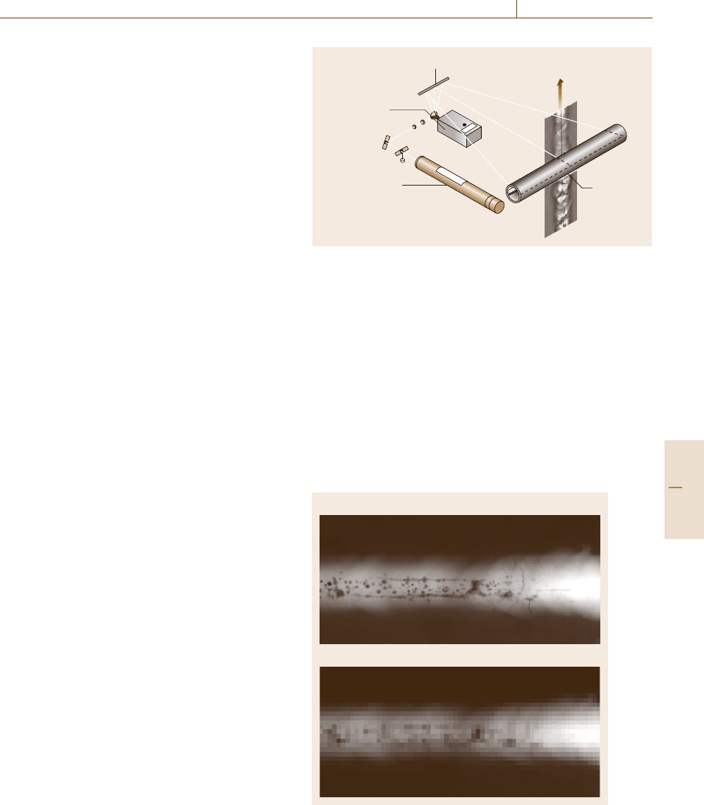
For example, digitization with a laser scanner pro-
ceeds as shown in Fig. 16.42. The film passes a collec-
tion tube. A laser beam (wavelength about 680 nm, red)
with a fixed diameter (e.g. 50 μm) scans the film. The
diffuse transmitted light through the film is integrated
by the collection tube and registered by a photo-
multiplier (PMT) on top of the collection tube (not
shown in Fig. 16.42). During the scan the folding mir-
ror deflects the laser beam and moves the spot along
a horizontal line on the film. The film is advanced with
a constant speed. The resulting voltage at the photo mul-
tiplier is proportional to the light intensity behind the
film. After logarithmic amplification a digitization with
Table 16.2 Application areas of digital industrial radiology (DIR)
Digital industrial radiology
Film replacement New industrial areas
Standards, Nonstandard Serial part Computed
regulations applications inspection tomography
Welding Wall thickness, Automated defect 3-D-casting
corrosion, erosion recognition (ADR) inspection
Casting Buildings, bridges Completeness test Ceramic composites, plastics
Electronics Plastics, composites Dimensional check Special applications
Food, tires, wood ...
Table 16.3 Classification of digitization systems by tech-
nology
Principle Scanner type
Point-by-point digitization Laser scanner
Line-by-line digitization CCD line scanner
Array digitization CCD camera
12 bits yields grey values that are proportional to the
optical density of the film.
The essential difference to other digitization principles
is the reversed optical alignment. The laser scanner il-
luminates with focused light and measures the diffuse
light intensity behind the film. All other methods illu-
minate the whole area of the film with diffuse light (the
film is illuminated with a diffuser) and measure the light
intensity that passes the film in one direction at each
spot (camera objective or human eye in classical film
inspection).
Complementary metal--oxide--semiconductor(CMOS)
cameras, which generate a logarithmic output signal rel-
ative to the input light intensity, are also available. In
this case the digitized grey values will be proportional
to the film density, and do not follow the exponential
characteristics as digitized with charge-coupled device
(CCD) chips. This is an advantage over CCD chips for
the digitization of radiographic films, but the signal-to-
noise ratio for CMOS detectors is usually considerable
lower than for CCD chips.
The standard ISO/EN 14096-1/2 defines the qualifi-
cation procedure and the minimum requirements for
film digitizers in NDT. This is particularly impor-
tant for microradiography. NDT applications employ
x-ray energies of 50–12 000 keV. The standards require
a spatial pixel size of 15–250 μm depending on the en-
ergy. This corresponds to a required spatial resolution
of 16.7lp/mm (line pairs per millimeter) for energies
< 100 keV and e.g. 1 lp/mm for 1300 keV.
Part D 16.2
Performance Control 16.2 Industrial Radiology 909
On the basis of the image quality of film radiogra-
phy the standard requires three quality classes: DA,DB
and DS. The user may select the testing class based on
the needs of the problem.
•
DS: the enhanced technique, which performs the
digitization with an insignificant reduction of
signal-to-noise-ratio and spatial resolution; applica-
tion field: digital archiving of films (digital storage);
•
DB: the enhanced technique, which permits some
reduction of image quality; application field: digital
analysis of films; films have to be archived;
•
DA: the basic technique, which permits some re-
duction of image quality and further reduced spatial
resolution; application field: digital analysis of
films; films have to be archived.
Image Processing
A digital image is physically not more than a data file
in a computer system linked to a program capable of
displaying its contents on a screen or printout dot by dot.
That means it consists of an array of individual image
points. These are called picture elements (pixel). The
pixels are in practice small rectangles (squares) showing
a certain color and brightness.
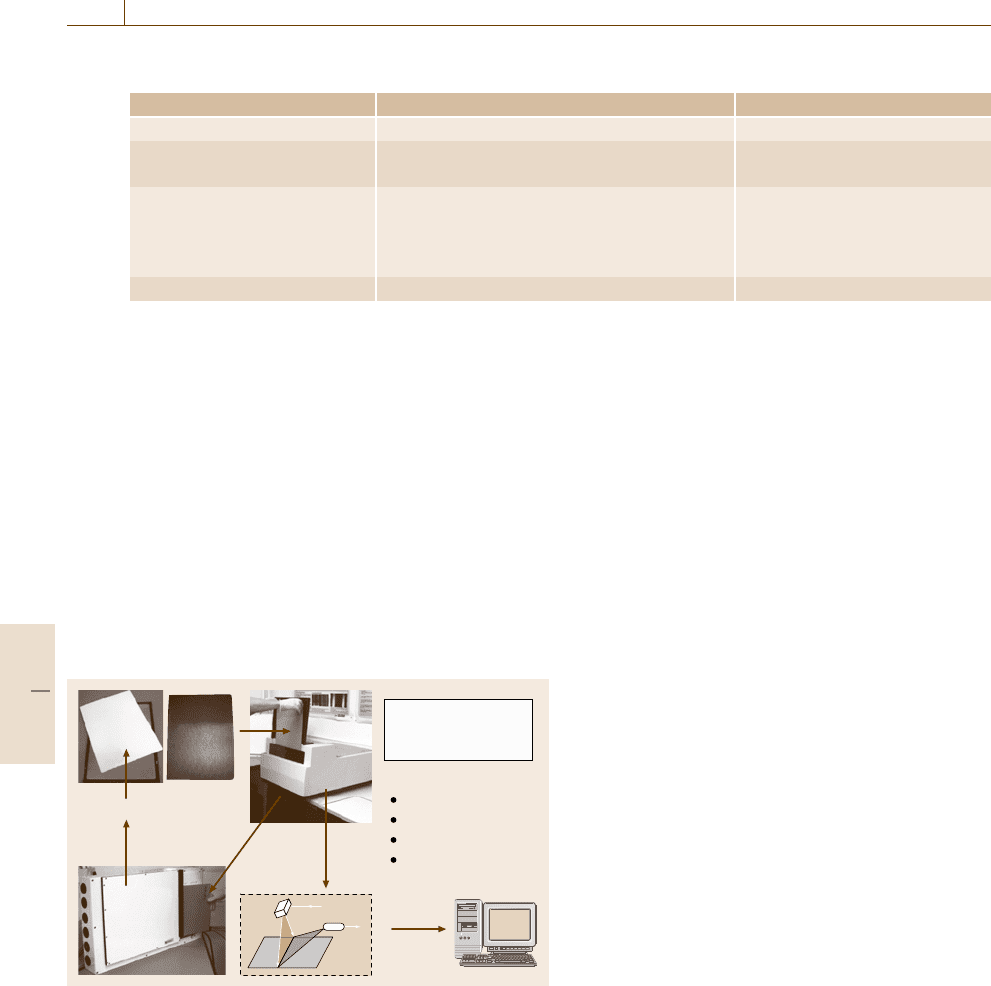
The image resolution depends on the number of pix-
els within a given area; the more the better (Fig. 16.43).
Radiography commonly deals only with grey-level im-
ages.
The numerical values of any pixels within an im-
age can be subjected to various kinds of calculations.
Each pixel is characterized by a grey (intensity) value,
which is proportional to its brightness. The most triv-
ial step is to adjust brightness and contrast. This allows
one to overcome the lower brightness of monitors com-
pared to commercial film viewers. While the human eye
can only distinguish between some 60–120 grey values
(at a given adaptation, equivalent to 6–7 bits of infor-
mation) a digital image may contain up to 65 536 grey
levels (i. e. 16 bits). The contrast and brightness oper-
ations are essential to select the range of interest. The
gamma transformation alters the linearity of the trans-
fer from the original digital values listed in the image
file to its brightness displayed on the screen, taking into
account the brightness sensitive perception of human
eyes.
Multiple-point calculations take advantage from re-
lationships between adjacent pixels of the image (matrix
operations). They are based on a variety of so-called
filter algorithms that are supposed to extract the de-
sired features from the total image information. They
Folding mirror
Galvanometer
Laser
Collection
tube
Film transport
Fig. 16.42 Principle of a laser scanner (“LS 85”, Kodak, USA)
may eliminate unwanted large, patchy intensity fluc-
tuations or noise masking other image details. Typical
filters are describes in Table 16.4. Processing of ra-
diographic images shows astonishing results that can
be found, together with filter recipes, in different text-
books [16.22,23].
Computed Radiography
and its Industrial Application
Phosphor imaging plates (IP) are image media for film-
less radiography. The technique is also called computed
radiography (CR). IPs are routinely used in medicine
and biomedical autoradiography. Different systems are
a)
b)
Fig. 16.43a,b Radiographic image of a test weld BAM5,
(a) 1024× 512 pixels; (b) 64 × 32 pixels
Part D 16.2
910 Part D Materials Performance Testing
Table 16.4 Typical image-processing filters
Filter Advantage Disadvantage
Low-pass filter (smoothing) Increases the signal-to-noise ratio Reduces the spatial resolution
High-pass filter Increases the contrast of fine details in Reduces the signal-to-noise ratio
relation to intensity changes in a wide range
Median filter Increases the signal-to-noise ratio, removes Reduces the spatial resolution
single peaks and outliers (single white or
black pixels such as salt and pepper distortions),
does not smooth edges
Edge filter Enhances edges or extracts edges to lines Increases the noise
available for NDT applications. Novel applications in
addition to film radiography emerge taking advantage
of the higher sensitivity (shorter exposure time) and the
digital processing as well as the capability to analyze
digital radiographs with affordable computer systems.
A set of standards was published 2005 in Europe and
USA, which defines the classification and practice of
CR systems [16.24].
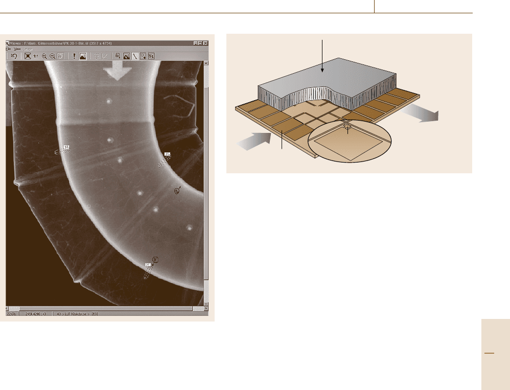
IPs are handled nearly in the same way as radio-
graphic films. After exposure, they are read by a laser
scanner producing a digital image instead of being de-
veloped like a film (Fig. 16.44). Any remaining latent
image can be erased with a bright light source so that
the same IP can be recycled up to more than 1000 ×.
An IP consists of a flexible polymer support which is
Expose
Reuse
High sensitivity
computed radiography
Phosphor
imaging plates
Read
High dynamics
Medium resolution
Reusable
Data output
Laser
PMT
IP
Erase
Fig. 16.44 Principle of application of phosphor imaging plates (IP)
for computed radiography (CR). The plate is exposed in a lightproof
cassette. The scanner reads the IP with a red laser beam. All ex-
posed areas emit stimulated blue light. The photomultiplier collects
the blue light through a blue filter and converts it into an electri-
cal signal. The signal intensity values are converted to digital grey
values and stored in a digital image file. Remnants of the image
on the IPs are erased by intensive light. They can be used usually
100–1000 × if they are handled carefully
coated with the sensitive layer which is sealed with
a thin transparent protective layer. The sensitive layer
of the most common systems consists of a mixture of
BaFBr doped with Eu
2+
. X-ray or gamma-ray quanta
result in an avalanche of charge carriers i. e. electrons
and holes in the crystal lattice [16.25].
These charge carriers may be trapped at impurity
sites i. e. electrons at a halogen vacancy (F-center) or
holes at an interstitial Br
+
2
molecule (H-center). Red
laser light (600–700 nm) excites electrons trapped in
aBr
−
vacancy (F
Br
-center) to a higher state from which
they may tunnel and recombine with a nearby trapped
hole. Transfer of the recombination energy excites
a nearby located Eu
2+
ion. Upon return to its ground
state this Eu
2+
ion emits a blue photon (390 nm). This
process is described as photostimulated luminescence
(PSL).
The advantages of IP technology are
•
linearity with radiation dose
•
high dynamic range, up to 10
5
•
sensitivity higher than with film
•
reusable for 1000 cycles
•
no chemical darkroom processing
•
capability for direct image processing.
The disadvantages are
•
limited spatial resolution, except in new high-
definition systems
•
high sensitivity in the low-energy range
•
sensitive to scattered radiation.
The available systems of phosphor imaging plates
and corresponding laser scanners cover radiation dose
differences of up to 10
5
. This feature reduces the
number of exposures for objects with a high wall-
thickness difference. It also compensates partly for
incorrectly calculated exposure conditions. The number
of so-called test exposures is reduced. The IP reader is
typically separated from the inspection site. CR is based
Part D 16.2
Performance Control 16.2 Industrial Radiology 911
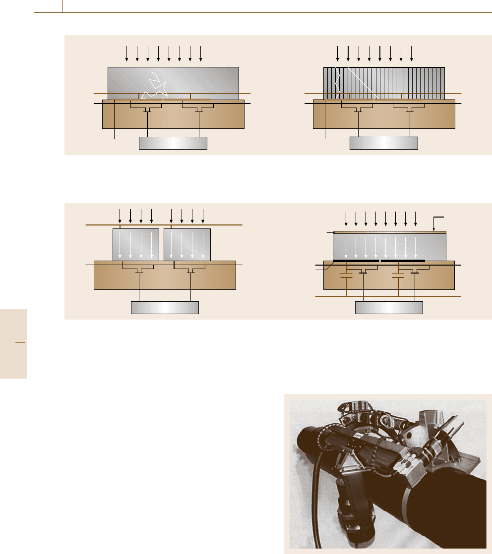
Fig. 16.45 Computer-based inspection of an insulated pipe
by projection radiography. The wall thickness is measured
by image processing in the marked areas
on flexible IPs [16.26]. High-definition CR systems can
provide a spatial resolution of better than 25 μm. This
is sufficient for weld and casting inspection of small
components at lower x-ray voltages as well as large
components.
Measurement of Pipe Wall Thickness for the
Evaluation of Corrosion, Erosion and Deposit
A typical application of the CR technology is radio-
graphic corrosion inspection in the chemical industry.
Figure 16.45 presents a typical example with a ther-
mally insulated pipeline. The insulation is covered
with an aluminum envelop. The radiographic inspec-
tion can be performed without removing the insulation.
This is a considerable advantage relative to the other
known methods. Radiographic pipe inspection for cor-
rosion and wall thickness measurement is a major
NDT technique for predictive maintenance. CR is
also more and more applied for inspection of valves
and armatures for functionality check and deposit
search.
X-rays
Line driver
Contacts
Switch
Scintillator
Amplifier,
multiplexer,
ADC
photodiode
Pixel matrix
Fig. 16.46 Scheme of a flat-panel detector: The scintillator converts
x- or γ -rays into light, which is detected by the photodiodes. They
are read out by thin-film transistors (TFT) on the basis of amorphous
silicon, which is resistant to radiation
Radiography with Digital Detector Arrays (DDA)
Flat-Panel Detectors. Two types of DDAs, also called
flat-panel detectors, are available on the market. The
first design (Fig. 16.46) is based on a photodiode ma-
trix connected to thin-film transistors (TFT) [16.27].
These components are manufactured of amorphous sil-
icon and they are resistant against ionizing radiation.
Alternatively to the amorphous silicon panels CMOS
arrays can be applied. The photodiodes are charged by
light which is generated by a scintillator converting the
incoming x- or gamma rays. This scintillator can be
a polycrystalline layer that causes some additional un-
sharpness by light scattering or a directed crystalline
system which acts like a face plate with lower un-
sharpness due to inhibited light scattering (Fig. 16.47).
The next generation (second type of DDAs) of flat
panels is based on a photoconductors like amorphous
selenium [8] or CdTe on a multi-microelectrode plate,
which is also read out by TFTs(Fig.16.48b). Di-
rect converting photodiode systems (Fig. 16.48a) are
not used in NDT yet, due to their low quantum effi-
ciency.
DDAs are suitable for in-house and in-field appli-
cations. In-field applications are characterized by harsh
environmental conditions in some areas, which implies
the risk of hardware damage and restricts the mobile
application of DDAs. Alternatively, digital data may be
obtained by film digitization or directly by the applica-
tion of CR.
Line Detectors. The classical concept of NDT with
line detectors is based on a fixed radiation source,
moving objects and a fixed line camera. This is
Part D 16.2
912 Part D Materials Performance Testing
X-rays
a) b)
Phosphor
Photodiode
Row select
Visible Photons
Photodiode
Row select
Visible Photons
Bias
Output
Bias
Output
Cesium
iodide
X-rays
Fig. 16.47a,b Principle of amorphous-silicon flat panels with fluorescence screens. (a) Additional unsharpness is gener-
ated in the phosphor layer due to light scattering. (b) Needle crystals of CsI on the surface of the photodiodes improve
the spatial resolution because the crystals conduct the light to the photodiodes like fiber light conductors
X-rays
a) b)
Diode
Row select
Electrons Electrons
Row select
Bias
Output
Bias
Output
Contact plate
Photo-
conductor
Collector
plate
X-rays
+V
Fig. 16.48a,b Principle of direct converting flat panels with amorphous silicon thin-film transistor arrays for read out.
There is no light scattering process involved. The spatial resolution is determined by the pixel size of the detector
array. (a) Photodiodes convert directly the x-ray photons to electrons. This technique is suitable for low-energy ap-
plications. (b) A semiconductor (e.g. amorphous selenium or CdTe) is located on microelectrodes in a strong electrical
field. Radiation generates charges, which can be stored in microcapacitors
the typical concept for baggage, car and truck in-
spection. Line detectors are available with a resolu-
tion of 0.25–50 mm. The most common principle is
the combination of scintillator and photodiodes. The
scintillator is selected in accordance to the energy
range.
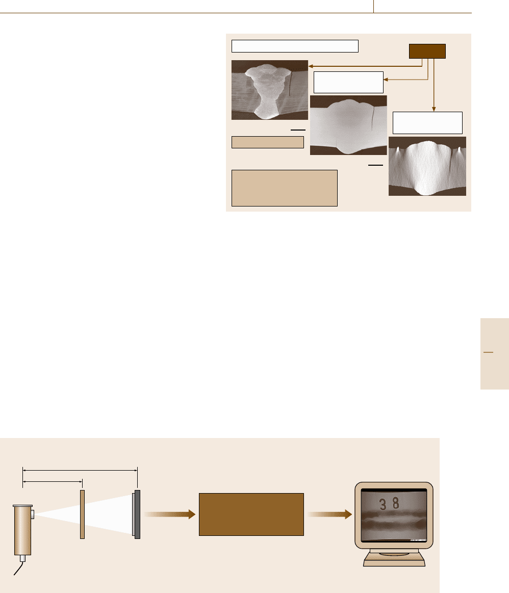
Mechanized X-ray Inspection of Welds. High-reso-
lution lines have been introduced for weld inspec-
tion [16.28]. Figure 16.49 shows a mechanized x-ray
inspection system, which is based on an x-ray tube,
a manipulation system and a line camera. The cam-
era consists of an integrated circuit with about 1200
photodiodes. A GdOS scintillator screen is coupled to
the diodes. New applications take advantage of TDI
(time-delayed integration) technology to speed up the
scan [16.29]. Several hundred lines are used in parallel.
The signal is transferred from line to line synchronously
Fig. 16.49 View of the line scanner. The x-ray tube and
camera are mounted on a manipulator for mechanized in-
spection of pipes
Part D 16.2
Performance Control 16.2 Industrial Radiology 913
with the movement of the object or the scanning sys-
tem. The information is integrated on the chip and the
speed enhancement corresponds to the number of lines
used.
Specialized tomographic routines were developed
to reconstruct a three-dimensional (3-D) image of
the weld [16.28]. This method is very sensitive to
cracks and lack of fusion. The depths and shape of
these defects can be reconstructed and measured. Fig-
ure 16.50 shows the image of a reconstructed crack in an
austenitic girth weld in comparison to a cross-sectional
metallography.
Automated Evaluation of Digital X-ray Images:
Serial Inspection in Automotive Industry
Fast digital x-ray inspection systems are used in the
serial examination of industrial products since this
technique is capable of detecting flaws rather dif-
ferent in their nature such as cracks, inclusions or
shrinkage. They enable a flexible adjustment of the
beam direction and of the inspection perspective as
well as online viewing of the radioscopic image to
cover a broad range of different flaws. This eco-
nomic and reliable technique has become of essential
significance for different applications. The configura-
tion of such systems is schematically represented in
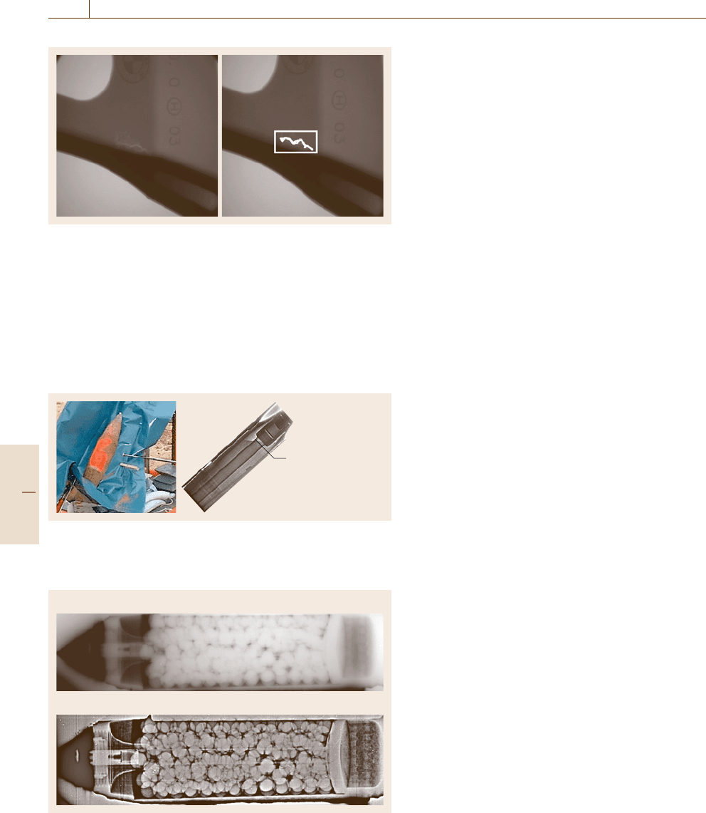
Fig. 16.51.
The object, irradiated from one side by x-rays,
causes a radioscopic transmission image in the detec-
tor plane via central projection. The relation between
the focus–detector distance (FDD) and the focus–object
distance (FOD) determines the geometrical magnifi-
cation of the image. An image converter such as an
x-ray image intensifier, a fluorescence screen or a dig-
ital detector array (DDA), also called a flat-panel
Attenuation image
FDD
Digital signal
Test sample
Falt panel
detector
Image processing system
X-ray tube
FOD
Monitor
Monitor image
Data acquisition and
digital image
processing/evaluation
Fig. 16.51 Schematic set up of a digital industrial radiology system
Digital – Metallographic sectioning
Metallographic
cross sections
Tomographic
cross sections
Measured values:
Result
Etched
Austenitic weld sample
Not etched
5mm
5mm
Metallography –8.1 mm
Planartomography –7.7 mm
Fig. 16.50 Reconstructed crack in an austenitic weldment com-
pared to the metallographic cross sections
detector, converts the x-ray image to a digital im-
age.
Light alloy castings are widely used, especially
in automotive manufacturing. Due to imperfections
of the casting process, these components are prone
to material defects (e.g. shrinkage cavities, inclu-
sions). These parts are frequently used in safety-
relevant applications, such as steering gears, wheels
and increasingly wheel suspension components. These
parts have to undergo a 100% x-ray inspection for
safety.
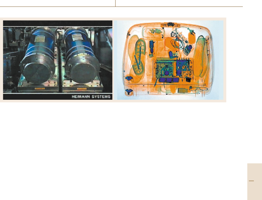
A fully automated x-ray inspection system for
unattended inspection can guarantee objective and re-
producible defect detection (see example in Fig. 16.52).
The decision whether to accept or to reject a speci-
men is carried out according to the user’s acceptance
Part D 16.2
914 Part D Materials Performance Testing
Fig. 16.52 Defect detection with an automated system. Left:origi-
nal image; right: detected flaw
specification. These systems are known as automated
defect-recognition (ADR) units.
Automated x-ray inspection is also used for
a novel field of application: the check of complete-
ness and function. For example, when the presence
and deformation of parts have to be checked. Fur-
A surface of a liquid
indicates chemical
warface agents
Fig. 16.53 Inspection of a grenade of World War I, filled with chem-
ical warfare. The chemical agent can be detected, by visualization
of the liquid-level line inside the grenade
a)
b)
Fig. 16.54a,b Radiograph of a shrapnel grenade: (a) original im-
age, and
(b) high-pass-filtered image
thermore distances and spatial dimensions can be
examined.
16.2.5 Applications of Radiology
for Public Safety and Security
Public safety and security is yet another application
field of digital industrial radiology. Since explosives
entail a considerable threat it is a central issue of
all security measures to detect them in time. There
exist a variety of different methods for explosive detec-
tion [16.30].
Inspection of Unexploded Ordnance (UXO)
Grenades containing warfare substances are identified
by the presence of a liquid surface visible in the respec-
tive radiograph (Fig. 16.53). They have to be inspected
to assign them to the appropriate way of safe disposal.
To detect a putative liquid filling, the suspected ammu-
nition is radiographically inspected in a tilted position.
If this shows the surface of the liquid, then the grenade
is filled with a warfare substance (such as e.g. mustard
gas or phosgene). Image processing reveals further de-
tails. Figure 16.54 shows how the digital radiograph
of a shrapnel grenade was enhanced by image pro-
cessing.
Dual-Energy Radiography for Baggage Control
The dual-energy technique is widespread in modern
baggage-inspection equipment. It provides additional
information about the chemical composition of the in-
spected material. The technique takes advantage of the
fact that radiation of different energy is absorbed dif-
ferently by the various elements. The absorption is
a function of the atomic number of the absorbing ele-
ments. As a consequence, radiographs taken at a lower
and a higher x-ray energy level are not identical. The
ratio between the logarithmic grey values of such a pair
of images represents the chemical composition of the
absorbing material and is independent of its layer thick-
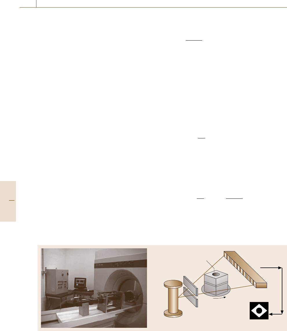
ness. Figure 16.55 shows a dual x-ray tube set and
a typical dual-energy radiograph of a bag. This tech-
nique provides the operator with color-coded images,
where the color indicates the chemical composition
of the inspected specimen. This can provide hints of
the presence of explosives or contraband. Advanced
versions of inspection units include an additional spec-
trometer to measure the spectrum of the scattered
radiation. This method is rather sensitive and allows the
detection and specification of various chemical com-
pounds within the object.
Part D 16.2
Performance Control 16.3 Computerized Tomography – Application to Organic Materials 915
Fig. 16.55 Dual x-ray tube assembly for dual-energy inspection of baggage and typical image of a bag. The atomic num-
ber of the components in the object are usually represented by the color: blue – high atomic numbers (e.g. metals); green
– medium atomic numbers (e.g. glass, polyvinyl chloride); yellow to brown – low atomic numbers (e.g. carbon hydrates)
16.3 Computerized Tomography – Application to Organic Materials
For tasks of materials performance control, tomog-
raphy with x-rays supported by computers, in short
computerized tomography (CT), is gradually spread-
ing in industry. Tomography, born in the medical field,
makes it possible to show 0.1% differences in the den-
sity of materials. Moreover, the tomographic section of
an object under study, which is reconstructed in three-
dimensional space, is not affected by the rest of the
volume exposed to irradiation, and the geometry is well
defined. The section-by-section reconstruction makes it
possible to achieve a complete exploration of the object.
For materials classes like polymers, such as natural rub-
ber (NR) or styrene butyl rubber (SBR), and composite
materials, such as polymer matrix composites, this
method is efficient, gives high resolution and reliable
results. However, industrial application of a medical
scanner, as presented here, is applicable only for low-
density materials (4 < g/cm
3
). The application of CT
to materials of higher density is discussed in Sect.16.4.
We can discern four application fields for computer
tomography
1. nondestructive testing of big components;
2. nondestructive of small pieces;
3. materials study;
4. microtomography.
In this section, we will present the method and the ter-
minology within the scope in which the medical scanner
is commonly used. Then, we will deal with examples
chosen to share the performances of this technique for
industrial applications.
16.3.1 Principles of X-ray Tomography
When x-ray tomography is used, a collimated beam
goes through the tested object before being received by
a row of detectors opposite the x-ray source. The ob-
ject is then rotated through an angle of 180
◦
.During
the rotation, the attenuation of the intensity of the x-ray
beam is measured in a finite number of angular incre-
ments. Data acquisition is achieved by a computer that
carries out the reconstruction of the object with the help
of a suitable algorithm.
A x-ray CT is essentially based on the measure-
ment of the different absorption coefficient of the
materials crossed by a penetrating beam such as x- or γ -
rays [16.31–39]. The CT image gives linear attenuation
coefficients in the slice for each point, which depend on
the physical density of the material, its effective atomic
number and x-ray beam energy. The attenuation in the
intensity of a single x-ray beam is then defined by the
equation of Lambert–Beer as the following;
I = I
0
exp(−μL) , (16.23)
where I
0
is the incident intensity, I is the transmitted
intensity, μ is the linear attenuation coefficient and L is
the thickness of the absorber.
Part D 16.3
916 Part D Materials Performance Testing
Thus, a tomographic system measures the attenu-
ation of intensity from different angles to determine
cross-sectional configuration with the aid of a comput-
erized reconstruction. The general view of the medical
scanner (x-ray CT) equipped with a mechanical test de-
vice – electrical jack plus carbon-fiber tube and also the
scanning system – is shown schematically in Fig. 16.56.
It consists of an x-ray source, a collimator, a detector
array and a computer system with data-storage media.
When going through a material, a beam of x-ray
undergoes an absorption that depends on the three fol-
lowing parameters.
1. The nature of the materials, or more exactly the re-
spective densities of the elements that make up the
material that is put in the path of the radiation (the
linear absorption coefficient);
2. The thickness of each of these elements;
3. The incident intensity of the radiation.
The attenuation of the radiation through an object
complies with the Lambert–Beer law, which governs
every absorption phenomenon
I = I
0
e
μL
. (16.24)
The medical scanner is able to measure the x-ray atten-
uation in Hounsfield units or tomography density even
if it does not give local mass density. To obtain this,
it is necessary to make a calibration versus a reference
which is water. The tomography density (DT) is a rel-
ative measure of the attenuation coefficient with regard
to the water. For this reason, we need to know the value
given to water in the tomography scale in Hounsfield
units (H). Basically with a constant X photon energy,
Sample
X-ray source
Collimator
Testpiece
rotation
Linear x-ray
detector
array
CT Image
Fig. 16.56 Medical scanner equipped with a mechanical test device (electrical jack plus carbon fiber tube) and schematic
of computed tomography system
the DT depends of the attenuation coefficient by a theo-
rical relation where K is a constant equal to 1000
D =
μ −μ
w
μ
w
. (16.25)
This relation of conversion between the attenuation
coefficient and the tomographic density is based on wa-
ter attenuation coefficient value, which is 1.8cm
−1
at
73 keV, corresponding to density zero in the Hounsfield
tomography scale.
This conversion is done in two steps.
•
An intermediate scale is chosen. In this new scale,
for the water, there is a relation between K and C of
K =Cμ
w
(16.26)
and the attenuation coefficient for a given material
is given by
μ
int
=
K
μ
w
μ. (16.27)
The tomographic density is linear with regard to the
intermediate attenuation μ
int
and the water density
must be equal to zero.
•
Make a translation in order to fulfil the condition
DT =μ
int
−K , (16.28)
so that
DT =
K
μ
w
μ −K =
μ −μ
w
μ
w
K . (16.29)
Calibration has been done with several materials in
order to have an empirical relation average DT of ma-
terials and respective attenuation coefficient. Table 16.5
presents some results.
Part D 16.3
Performance Control 16.3 Computerized Tomography – Application to Organic Materials 917
Table 16.5 Attenuation coefficients and tomographic den-
sities of some materials obtained with a medical scanner
Material μ(cm
−1
) DT (H)
Polyethylene 0.172 −72
Water 0.191 −0.4
Nylon 0.210 90
Polyester 0.217 139
Araldite 0.219 147
Rubber 18160/52 0.224 165
Delrin 0.262 349
Ebonite 0.288 434
Rubber 19199/48 0.340 729
Teflon 0.340 729
Conventional radiography makes it possible to show
defects bound up with variations of density compared
with the material as a whole. Thus, under most cir-
cumstances, inclusions, cracks, porosities, etc. can be
shown.
Nevertheless, radiography takes into account every-
thing the beam meets while going through the material
and gives a plane projection of them. That is why cracks
perpendicular to the beam are liable to escape detection.
Tomography breaks free from the drawbacks of
x-radiography by exploring the object with a 180
◦
ro-
tation, thanks to three-dimensional reconstruction, so it
is possible to know the absorption density of any point
within a given volume.
The units of absorption density are those used in
medicine. The following references are given:
1000 H (Hounsfield) units Density of dried bone
0 Density of water
−1000 H units Density of air
This scale is suitable for composite materials whose
H density is about a few hundred units because of their
nature. The standardization carried out to associate the
medical unit with the density of the bulk Δ
ρ
gives for
one H unit: Δ
ρ
=1×10
−3
with a 120-kV x-ray source.
This implies that the medical scanner makes it pos-
sible to show variations of volumetric density of about
a thousandth.
The highest Z material that can be evaluated with
a medical scanner is aluminum.
The objectives of this paragraph are to present the
performances of x-ray tomography in order
•
to detect internal geometric defects,
•
to perceive the evolution of mechanical, physical,
chemical damage,
•
to display homogeneous variation related to pro-
cessing,
•
to observe differences in texture, chemical concen-
tration at the meso- and nanoscale.
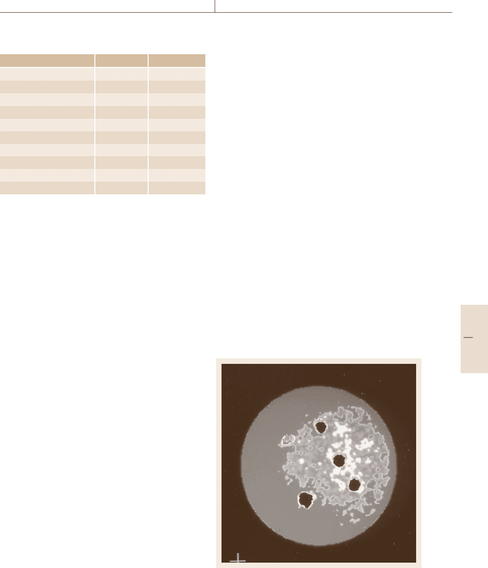
16.3.2 Detection of Macroscopic Defects
in Materials
Using a medical scanner, metal matrix composites pro-
cessed by squeeze casting have studied. The first step
was to test the alumina preforms, which are disks with
85 mm diameter and 15 mm thickness. In some disks,
spherical defects were introduced during the process-
ing. Figure 16.57 presents the results of the tomographic
examination. The average Hounsfield density of the ce-
ramic preform is about −215. However, there is a large
difference of x-ray attenuation between the center of the
specimen and the edge, where the density is a maxi-
mum of 118. In fact, the density is lower in the center of
the specimen because the volume fraction of alumina is
smaller than near the edge. Thus, it is possible to check
the processing of the preform with tomographic obser-
vation as well as the repartition of alumina platelets
which is very difficult using regular experimental meth-
ods. Of course, it is very easy to detect defects in
ceramic preforms, as is shown in Fig. 16.57.
Fig. 16.57 Defects in ceramic preform
Part D 16.3
