Czichos H., Saito T., Smith L.E. (Eds.) Handbook of Metrology and Testing
Подождите немного. Документ загружается.

888 Part D Materials Performance Testing
16.7 Characterization of Reliability................ 949
16.7.1 Statistical Treatment of Reliability .. 951
16.7.2 Weibull Analysis........................... 952
16.7.3 Reliability Test Strategies............... 956
16.7.4 Accelerated Lifetime Testing .......... 959
16.7.5 System Reliability......................... 962
16.7.6 System Reliability Estimation
in Practice................................... 964
16.A Appendix ............................................. 967
References .................................................. 968
16.1 Nondestructive Evaluation
Nondestructive evaluation is an important method for
performance control and condition monitoring. In en-
gineering systems, flaws and especially cracks in the
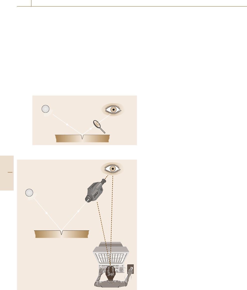
Light source Eye
Inspection tool
lens, endo-
scope
Fig. 16.1 Direct visual inspection
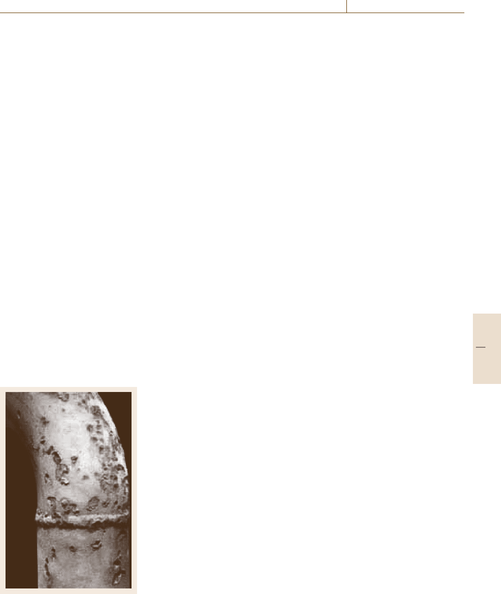
Light source
Inspection
tool
endoscope
Evaluation
Camera
Fig. 16.2 Indirect or remote visual inspection
materials of structural systems’ components can be cru-
cially detrimental to functional performance. For this
reason the detection of defects is an essential part of
quality control of engineering systems and their safe
successful use. Control techniques are often listed un-
der a variety of headings such as nondestructive testing
(NDT), nondestructive evaluation (NDE)orsometimes
nondestructive inspection. Applications of NDT tech-
niques, however, are much deeper and broader in scope
than just the detection of defects. The determination of
various material properties, such as elastic constants of
solids or the microstructure and texture of solids are also
covered under the NDT title.
According to the wide scope of this field, a plethora
of physical methods are employed. Established methods
include radiography, ultrasound, eddy current, mag-
netic particle, liquid penetration, thermography and
visual inspection techniques. Applications of NDE in
industry are as wide ranging as the techniques them-
selves and include mechanical engineering, aerospace,
civil engineering, oil industry, electric power industry
etc. A large number of components are also in the focus
of interest because engineered structures are an inte-
gral part of the technological base necessary for our
lives and the public infrastructure. The operation of
NDT techniques in several industries is standard prac-
tice, for example to support condition monitoring for
the proper functioning of the daily use of electricity, gas
or liquids in which pressure vessels or pipes are em-
ployed and where the correct operation of components
under applied stress plays a large role for safety and
reliability.
16.1.1 Visual Inspection
Visual examination means, in principle, inspection with
eyesight [16.1,2]. (For the fundamentals of optical sens-
ing see Sect. 11.7.) In the case of NDT, visual inspection
has a much broader meaning. There are differences
in the aim of the visual inspection if: (i) only sur-
face characteristics, such as scratches, wear or corrosion
Part D 16.1
Performance Control 16.1 Nondestructive Evaluation 889
phenomena are of interest, or (ii) detection of cracks or
deformation is included.
The first point (i) can be described as integral vi-
sual inspection and the second point (ii) as specific or
selective visual inspection. If between the eye of the
inspector and the surface of the test object the opti-
cal path is not broken then a direct visual inspection is
performed (Fig. 16.1). Such inspection is either integral
or selective. Direct visual inspection means examina-
tion using eyesight and sometimes simple tools such as
artificial illumination. Selective visual inspection uses
additional equipment including hand lenses, mirrors,
optical microscopes and telescopes and, for the docu-
mentation of the inspection results, storage media such
as photography or cameras in combination with a mon-
itor. If inspection is carried out by the evaluation of
photographs, video films or by robotics an indirect or re-
mote visual inspection is performed (Fig. 16.2). Visual
inspection can be carried out in almost all areas where
preventive maintenance is required. Visual inspection is
the oldest and most common form of corrosion inspec-
tion, applied to surface corrosion, intergranular stress
corrosion, and some kinds of pitting. Several corrosion
phenomena are detectable using direct visual inspection
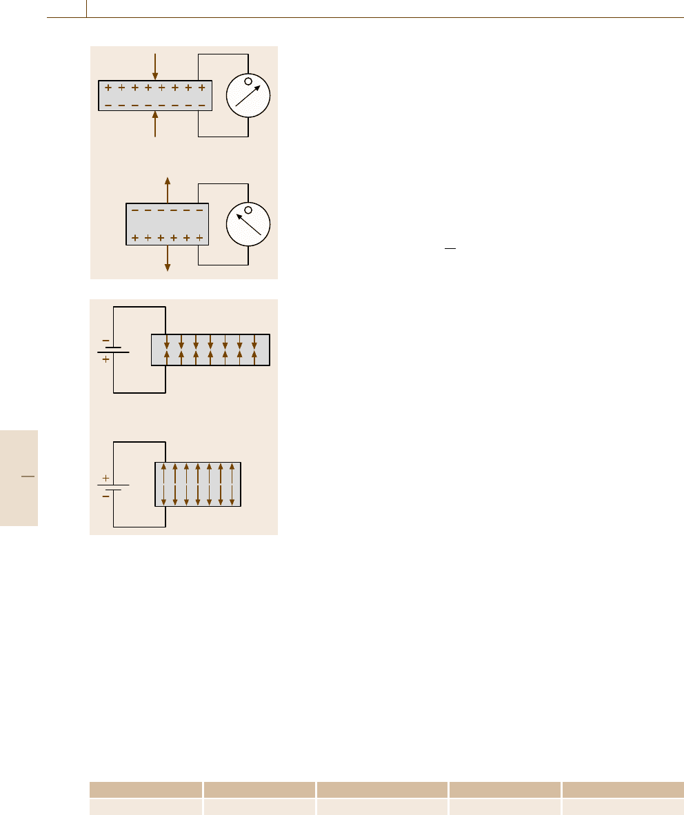
techniques. An example showing a corroded surface
is presented in Fig. 16.3. Clearly visible is the scarred
surface in the elbow region of the pipe. This exam-
ple illustrates that the visual technique is quick and in
most cases economical. Various types of failure are de-
tectable but the reliability of the inspection is highly
dependent on the skill and training of the examiner.
Fig. 16.3 Cor-
roded pipe
16.1.2 Ultrasonic Examination:
Physical Background
Sound travels in solids, liquids and gases with a velocity
depending on the mechanical properties of the material.
Imperfections such as cracks, pores or inclusions cause
sound-wave interactions which result in reflection, scat-
tering and general dampening of the sound wave [16.3–
6]. This dampening of the sound waves is responsible
for the distance traveled by the sound. In liquids sound
can travel large distances; on the other hand, in coarse-
grained solids the traveling distance may be only a few
centimeters due to scattering. Sound directions and the
estimation of the distance to the source are not easily
obtainable by simple methods. More precise techniques
are necessary to overcome these problems. This requires
the use of narrow sound beams.
In nondestructive evaluation (NDE) narrow sound
beams using short wavelengths can be formed when
the ultrasonic source size is much larger than the
wavelength. Nondestructive testing is carried out using
ultrasonic waves at high frequencies above the audible
range, higher than approximately 20 kHz and up to the
range of some hundred MHz.
Historically, the development of methods for ultra-
sonic materials testing in the industry started at the end
of the Second World War. Although the orientation of
bats using sound waves was an established phenom-
ena, the discovery of the piezoelectric effect by Jacques
and Pierre Currie 1880 and 1881 [16.3] was of critical
importance for the application of ultrasound. The the-
ory of sound propagation in solids was developed by
Lord Rayleigh between 1885 and 1910, as well as the
development of early electronic devices.
Sound-field generation and reception is performed
using special devices, so called ultrasonic transducer
or ultrasonic probes. The active sound-field genera-
tion tool is in the most cases a special ceramic with
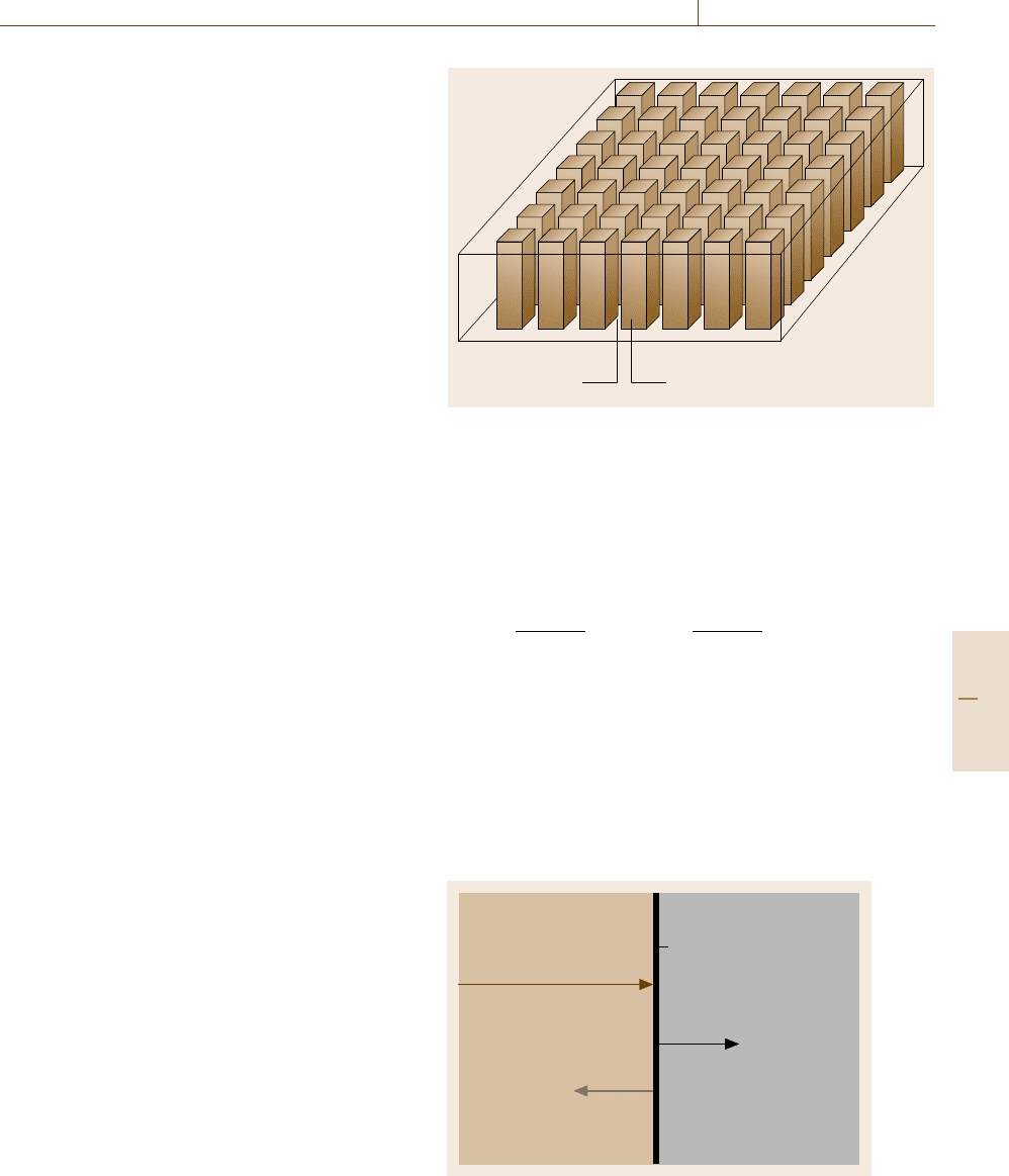
piezoelectric properties. A piezoelectric material has the
characteristic that, if it is deformed by an external me-
chanical pressure, electric charges are produced on its
surface (Fig. 16.4). This effect was discovered in 1880
by the brothers Curie. The reverse phenomenon, ac-
cording to which such a material, if placed between
two electrodes, changes its form when an electric po-
tential is applied, was discovered soon afterwards in
1881 (Fig. 16.5). The first effect is referred to as the di-
rect piezoelectric effect, and the second as the inverse
piezoelectric effect. The direct effect is used for mea-
suring and the inverse effect for producing mechanical
pressures, deformations and oscillations.
Part D 16.1
890 Part D Materials Performance Testing
F
F
F
F
Fig. 16.4 Direct
piezoelectric
effect
Fig. 16.5 Inverse
piezoelectric
effect
Generation of Ultrasound
Most transducers used in ultrasonic nondestructive
inspection are based on the piezoelectric effect. Gen-
eration of ultrasound is achieved using the inverse
piezoelectric effect, and the receiving procedure is
carried out with the direct piezoelectric effect. The prin-
ciple of the generation and reception of ultrasound was
explained and demonstrated with the help of the quartz
crystal. However for the time being other materials
with piezoelectric properties can be used to advantage.
Today, piezoelectric ceramic is most commonly used,
typical examples include barium titanate (BaTiO
3
),
Table 16.1 Sound velocities of piezoelectric ceramic materials used for ultrasonic transducers
Material BaTiO
3
PZT (P5) PbNb
2
O
6
PVDF
Sound velocity (m/s) 5200 4200 3300 1500–2600
lead zirconate titanate (PbZrO
3
–PbTiO
3
solid solution
PZT), lead meta-niobate (PbNb
2
O
6
), barium sodium
niobate (Ba
2
NaNb
5
O
15
) and the polymer polyvinyli-
dene fluoride (PVDF). The manufacturing process and
material properties can be varied within certain limits,
achieving a large range of acoustical properties, which
are normally customized to a specific application. These
materials have a much higher so-called electromechan-
ical coupling factor than quartz. The frequency of
the ultrasonic signal comes from the thickness of the
piezoelectric ceramic plate. The correlation between
thickness and frequency f
0
isgivenby(16.1).
f
0
=
c
2t
, (16.1)
where c is the velocity of sound, and t is the thickness
of the piezoelectric ceramic plate.
With knowledge of the sound velocity c of the
piezoelectric ceramic, the frequency f
0
is adjustable by
varying the thickness t of the ceramic. In Table 16.1 the
average sound velocities of common ceramic materials
are listed.
Such ceramic material, in the form of monolithic
discs, were, and are used for ultrasound generation.
In the meanwhile, also other crystal configurations
are the basis for ultrasound generation. The use of
1–3 composite materials has the advantage due to
a higher coupling coefficient and a better effective-
ness for ultrasound generation in comparison with
monolithic ceramics and polymers. At the Pennsylva-
nia State University’s Materials Research Laboratory
developed a large variety of piezoelectric composite
materials that consist of a ceramic and a polymeric
phase with different connectivities [16.7, 8]. The con-
nectivity in one, two, or three dimensions in a composite
is designated as “1, 2, or 3”. Therefore, a piezocom-
posite consisting of piezoelectric ceramic rods aligned
in parallel and embedded in a polymeric resin ma-
trix is called a “1–3” composite. The ceramic rods are
connected in only one direction, namely the poled di-
rection of the material, having a connectivity of “1”.
On the other hand, the polymer phase connects in all
three dimensions, having a connectivity of “3”. Fig-
ure 16.6 shows schematically the 1–3 piezocomposite
arrangement [16.9–11]. From the picture in Fig. 16.6,
it seems to be easily to produce such ceramic ma-
Part D 16.1
Performance Control 16.1 Nondestructive Evaluation 891
terials with the knowledge of wafer technology, but
there are some difficulties looking to the manufacturing
processes. These difficulties have limited, to a de-
gree, their applicability and have increased the cost
of manufacturing piezocomposite probes. Research and
development activities in the past try to improve these
processes und to introduce piezocomposite transducers
for NDT.
Piezoelectric ceramic materials are mainly used for
the preparation of ultrasonic transducers, nevertheless
other physical properties can be utilized for generat-
ing and receiving ultrasound. Although many of these
methods produce weaker signals than are obtainable by
the piezoelectric effect, they offer a number of advan-
tages that in special cases makes their application in the
testing of materials useful. For many of these alterna-
tive techniques the energy is transmitted by electrical
or magnetic fields, which in principle make mechani-
cal contact with the metallic test piece unnecessary. The
conversion into, or from, acoustic energy takes place in
the surface of the workpiece concerned. Compared with
the piezoelectric oscillator, which requires direct cou-
pling, normally with a suitable medium, e.g. water, to
the workpiece, the surface of the workpiece forms in
this a part of the acoustic transducer.
Other possibilities for the generation of ultrasound
are the use of mechanical shock or friction effects,
the application of thermal effects by heating the sur-
face of a body suddenly (heat shock) the exploit of
electrodynamic effects based on the Lorentz force and
the magnetostrictive effect. Apart from the generation
of ultrasound using the electrodynamic effect the oth-
ers methods play at present a small role into the NDE
field.
Reflection and Transmission
of Ultrasonic Waves at Boundaries
Normal Beam Incidence. The behavior of an ultra-
sonic wave in an unlimited material is only possible
on a theoretical level because in reality every mater-
ial has boundaries. At such boundaries the traveling
wave is disturbed. If the boundary is in a direct con-
tact with a vacuum, transmission of the ultrasonic wave
through the boundary is impossible; total reflection
occurs. Consider an incident longitudinal plane wave
traveling perpendicular to a boundary or interface be-
tween two materials, as demonstrated in the schematic
diagram in Fig. 16.7 [16.3, 4]. For symmetrical reasons
only the reflected P
r
and transmitted P
t
waves are pos-
sible. The part of the reflected wave is characterized by
the reflection coefficient R and the part of the trans-
Resin between the
piezoelectric rods
Piezoelectric material
Fig. 16.6 Piezocomposite arrangement
mitted wave by the transmission coefficient T.Inthis
special case the reflection and transmission coefficients
only depend on the acoustic impedance W =ρc
L
where
ρ is the density of the material and c
L
the sound ve-
locity of the longitudinal wave. The equation for the
calculation of the two coefficients are as follows
R =
W
2
−W
1
W
1
+W
2
and T =
2W
2
W
1
+W
2
. (16.2)
The indexes 1 or 2 are used to define the two media
(Fig. 16.7). It is clearly visible from these equations that
100% of the sound is transmitted through the interface
if W
1
is equal W
2
. In reality what happens for a steel–
water interface is a combination of impedances often
given in ultrasonic examination (W
1
=45 × 10
6
Ns/m
3
for steel and W
2
= 1.55 × 10
6
Ns/m
3
for water) for
a steel–water interface. With these values a reflection
Medium 1 Medium 2
Boundary
Transmitted wave P
t
Reflected wave P
r
Incident wave P
e
W
1
= ρ
1
c
1
W
2
= ρ
2
c
2
Fig. 16.7 Normal incidence of a sound wave on a boundary
Part D 16.1
892 Part D Materials Performance Testing
Sound pressure
2
1
–1
–2
–1
–2
2
1
Sound pressure
Reflected
wave
P
r
P
d
a) b)
P
e
Reflected
wave
Incident wave
Incident
wave
Steel Water SteelWater
Transmitted
wave
Transmitted
wave
Fig. 16.8 Sound pressure values by reflection at a steel/water inter-
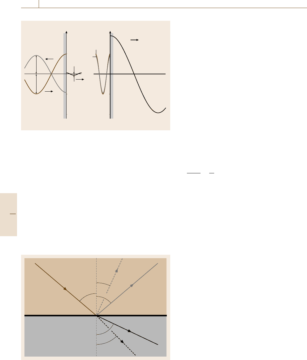
face
coefficient of −0.935 and a transmission coefficient
of 0.0065 is calculated. That means that 93.5% of
the sound field is reflected at the steel–water interface
(Fig. 16.8). The negative value of the reflection coeffi-
cient means that the phase of the reflected ultrasonic
wave has changed by 180
◦
compared with the inci-
dent wave. If we assume an interface steel–air then R
is −0.99998, i. e. nearly 100%. Such a material combi-
nation is given for instance if a crack is located in a steel
component. Therefore, when the sound wave strikes the
crack surface at a normal angle it can be detected with
a high probability.
Equations (16.2) are valid if the sound wave is trav-
eling perpendicular to the interface. The behavior is
Medium 2
Medium 1
Incident
longitudinal wave
Transmitted
longitudinal
wave
Transmitted
shear wave
Reflected
longitudinal
wave
Reflected
shear wave
Boundary length
greater than
sound wavelength
α
2
β
2
β
1
α
1
α
1
Fig. 16.9 Wave mode conversion at a boundary
more complex if the sound strikes the surface with an
angle > 0
◦
(Fig. 16.9). A mode conversion as illustrated
in the figure must be assumed, i. e. an incidence longitu-
dinal wave is reflected at the boundary as well as a shear
wave. A longitudinal and a shear wave are transmitted
into the second medium. This circumstances must be
taken into consideration by the calculation of the re-
flection and transmission coefficient. The situation is
similar if an incidence shear wave is assumed. For each
case presented in Fig. 16.9 two reflection and two trans-
mission factors are obtained.
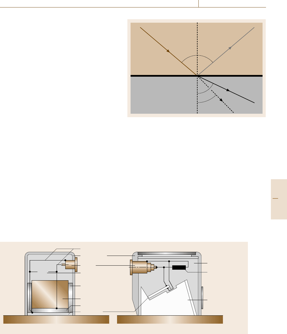
Inclined Beam Incidence. If an ultrasonic longitudinal
plane wave strikes a liquid–solid interface at an an-
gle α as demonstrated in Fig. 16.10 one reflected wave
and two transmitted waves are generated. The reflected
angle α is equal to the incidence angle whereas the
transmitted angles are different. These two angles are
dependent on the sound velocity for the different wave
types corresponding to the two materials. The calcula-
tion of these angles can be carried out using Snell’s law
sin α
1
sin α
2
=
c
1
c
2
. (16.3)
Using (16.3), all angles can be calculated if the sound
velocities and one angle are known. In the follow-
ing some consequences derived from the Snell’s law
are considered. The Plexiglas–steel interface is impor-
tant for ultrasonic angle beam probe construction and
therefore we will regard this material combination in
the following. The sound velocity for the longitudinal
wave is on average 2740 m/s for Plexiglas (perspex) and
5920 m/s for steel as well as 3255 m/s for the shear
wave in steel. Consideration of Snell’s law indicates
that two critical angles exist with respect to the refrac-
tion process on the interface. The first critical angel is
given when α
2
=90
◦
, i. e. the total reflection of the lon-
gitudinal wave. In this case only shear waves exist in
material 2. The second critical angle occurs when the
shear refracted angle is 90
◦
. If only shear waves will be
used in the practical application the Plexiglas wedge an-
gle β should be between 27.6 and 57.3
◦
. These values
are calculated using the above printed sound velocities.
Angle beam probes generating shear waves used for the
examination therefore have angles of incidence between
35 and 80
◦
.
Ultrasonic Transducers
In the following, the description of generating and re-
ceiving ultrasound with transducers (probes) will focus
on piezoelectric ceramic material [16.3, 5, 6] due to the
Part D 16.1
Performance Control 16.1 Nondestructive Evaluation 893
importance in practical applications. Such ultrasonic
transducers are optimized for different areas of appli-
cation [16.12–14] but the basic construction principle
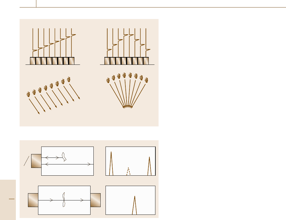
nearly always remains the same. Figure 16.11 shows
schematically typical commercial ultrasonic transduc-
ers as a part of the basic equipment for ultrasonic
examinations.
A longitudinal wave is generated using a straight
beam probe, presented in a schematic sketch in
Fig. 16.11a. The piezoelectric ceramic plate is behind
a protective coating (wear shoe/plate) and the back-
ing material (damping element) is largely responsible
for the pulse form. Together with an electrical adapta-
tion the ultrasonic pulse can be formed and optimized
to a particular application. As explained the thickness
of the ceramic delivers the middle frequency of the
pulse. This kind of probe has such an construction
that the waves have a perpendicular (straight) radia-
tion in relation to the test object’s surface. The size
of the piezoelectric ceramic together with the middle
frequency will determine important ultrasound probe
parameters, including the near-field length, divergence
angle and beam diameter, which are required to perform
reliable inspection. All these parameters of an ultrasonic
probe can be measured or calculated using simple equa-
tions. Figure 16.11b shows the principle drawing of an
angle beam probe for shear-wave generation. The shear
waves are generated due to refraction of the incident
longitudinal wave on the coupling surface. A common
ultrasonic angle beam probe can be employed to gener-
ate shear waves only. This is achieved if the wedge has
an angle between the first and the second critical an-
gle. So far, for the material combination perspex/carbon
steel, conventional probes are available generating shear
a) b)
Wire leads
Metal casing
Socket
Electrical
matching
Acoustic
insulation
Damping element
Electrical matching
Damping element
Perspex wedge
Object to be examined
Transducer
Wear plate
Fig. 16.11a,b Normal or straight beam probe (a) and angle beam probe (b)
Medium 2
Medium 1
(liquid)
Incident
longitudinal wave
Transmitted
longitudinal
wave
Transmitted
shear wave
Reflected
longitudinal wave
Boundary
α
2
β
2
α
1
α
1
Fig. 16.10 Inclined incidence at a liquid/solid boundary
waves with incidence angles of 45, 60 and 70
◦
. In recent
years with the development of electronic beam form-
ing so-called phased array probes [16.3] with variable
incidence angles have become available. The princi-
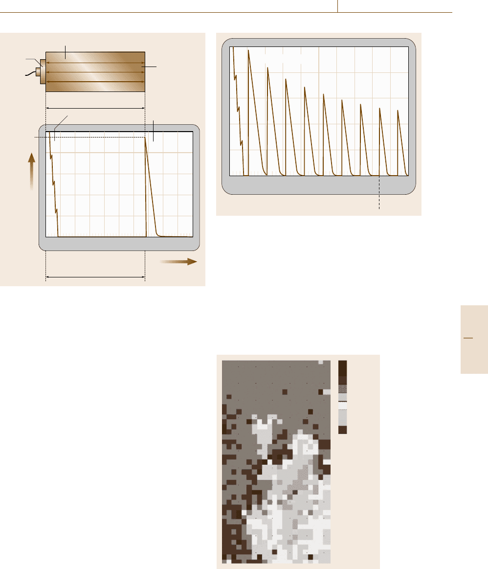
ple of the phased array probe can be explained with
the help of Fig. 16.12. The crystal is divided into sev-
eral elements. In the given example, eight elements
are illustrated. Each element is connected with the
transmitter/receiver part of special ultrasonic control-
ling equipment (phased array equipment). The time for
transmitting the main bang (transmitter pulse) is con-
trolled by the equipment in such a way that different
transmitter times can be achieved between the indi-
vidual elements. When the delay time Δt between the
elements is constant decreasing or increasing a varia-
tion of the incidence angle will occur. If Δt follows
Part D 16.1
894 Part D Materials Performance Testing
Transmitter pulses
8 crystal elements
Sound field direction
Variation of the incidence angle Variation of the focal distance
Fig. 16.12 Principle of a phased array probe
a)
b)
T
R
TR
Initial
pulse
Echo
rear wall
Echo defect
Amplitude varies
with defect
Fig. 16.13a,b Pulse-echo technique (a) and through-transmission
technique (b)
a predetermined curvature (like a lens) the sound filed
can be focused at a certain distance. Further a combina-
tion of both is also possible. With such a phased array
probe all incidence angle can be realized for longitudi-
nal as well as for shear waves. For the second case, if
Δt is specified by the curvature of a lens, a variation of
the focal distance is given by changing the curvature.
With advanced phased array equipment both changing
the angle and focal distance can be carried out in one
stage.
In the following some of sound-field distributions of
different kinds of probes are presented.
Sound Propagation in Solids
Sound propagation in materials is always connected
with an interaction of the ultrasonic pulse and the struc-
ture of the material. Especially for solid materials such
as steel the interaction with the grain size (scattering
and reflection) is sometimes not negligible mainly if
the wavelength and the grain size are within the same
dimensional range. Due to this interaction the sound
losses energy i. e. an attenuation of the sound will hap-
pen along the propagation direction. Another effect is
the frictional motion of the particles of the solid which
also has an attenuation effect but is based on the ab-
sorption of the ultrasonic intensity. Therefore the total
attenuation of the ultrasonic intensity is given as the
sum of the scattering and absorption coefficient (16.4)
μ =μ
s
+μ
a
. (16.4)
This attenuation must be taken into consideration during
the examination.
Principle of the Pulse-Echo
and Through Transmission Methods
Defects in materials caused scattering and reflection
of the ultrasonic wave and the detection of the re-
flected or transmitted waves allows the location of the
defect. A general illustration of the pulse-echo and
through transmission methods is shown in Fig. 16.13.
The through transmission normally requires access to
both sides of a component and is applied if the back-
reflection method cannot provide sufficient information
about a defect. For example, when small defects are
detectable which do not give adequate reflection signals.
The pulse-echo technique requires access to only
one side of the component. This is one advantage of this
method compared with the through-transmission tech-
nique. Another advantage of the pulse-echo method is
given due to the time-of-flight measurement because
the defect location (distance from the coupling surface)
can be estimated from the time required for the pulse
to travel from the probe to the discontinuity and back
and can be displayed on an oscilloscope. If the hori-
zontal sweep of the oscilloscope is calibrated with the
sound velocity into the material to be inspected, the re-
quired travel time from the probe to the reflector and
back corresponds to the distance of the reflector from
the coupling surface. This method is used extensively
in practice.
16.1.3 Application Areas
of Ultrasonic Examination
The application range of ultrasonic examination is very
broad. It covers, for example, wall thickness measure-
ment of structural components and the detection of wall
Part D 16.1
Performance Control 16.1 Nondestructive Evaluation 895
Probe
H
Echo
height
SR
Object to be examined
Back wall
Sound beam
d
Initial pulse
Transit time of US pulse
897654321010
Transit time
Back wall echo
Fig. 16.14 Principle of wall thickness measurements
thickness losses due to corrosion, erosion, wear etc.
Other application areas include the measurement of ma-
terial properties such as sound velocity, elastic constants
and the detection of flaws, e.g. cracks, slag inclusions,
lack of fusions, pores. The following examples illustrate
the application of ultrasonic examination for perfor-
mance control of components and engineering systems
in various areas of technology and industrial sectors.
Wall Thickness Measurement of Components
During the lifetime of a component their surface are
subjected to environmental stresses. Depending on the
environment corrosion phenomena must be taken into
consideration. A reduction of wall thickness can oc-
cur and as a consequence the safety factor that was
the basis for the construction may no longer be valid.
The principle of thickness measurement is illustrated
in Fig. 16.14 [16.15]. A straight-beam longitudinal
probe is coupled on the surface and the pulse echo from
the parallel flat opposite surface (back wall) is received
and displayed on the screen. The transit time of the
pulse corresponds with the wall thickness if the equip-
ment was calibrated with the correct sound velocity.
This method is sometimes known as a simple length
measurement.
RR
8
R
7
R
6
R
5
R
4
R
3
R
2
R
9
S
897654321010
8.4 0 °, 50
Fig. 16.15 Wall thickness measurement using multiple
echoes
Another method is to analyze multiple echoes which
are observed, i. e. multiple reflections of an acoustic
pulse propagating between the coupling surface and
the back wall (Fig. 16.15). Since the constant distances
between the echoes corresponds to the specimen thick-
ness d, then the whole transit time of the multiple
echo indications on the screen is also a multiple of the
wall thickness. An example of a corroded aluminum
plate from the aircraft industry is plotted in Fig. 16.16.
>1.8 mm
<1.7 mm
<1.6 mm
<1.5 mm
<1.3 mm
<1.2 mm
<1.4 mm
<1.1 mm
1.8 mm
Fig. 16.16 Wall thickness measurement
Part D 16.1
896 Part D Materials Performance Testing
For wall thickness estimation the measurement was
carried out using a mechanized ultrasonic immersion
technique. The different gray scales correspond with
different wall thicknesses.
All thickness measurement using ultrasound have in
common that the coupling conditions of the transducer
must be performed in the same manner, however also
care must be taken to use the correct sound velocity in
the material.
Weld Inspection
Ultrasonic weld inspection is done extensively around
the world, and the pertinent literature is published
in a multitude of journals, proceedings and technical
reports [16.14]. Usually, a shear-wave angle beam trans-
ducer is used to examine the weld and the adjacent
region in a halfskip and skip distance (Fig. 16.17). In
the figure the method of examining the root, the interior
and the top layer of the weld is presented. The skip dis-
tance can be calculated (16.5) where d is the thickness
of the specimen and α the beam angle
S
k
=2d tan α. (16.5)
The examination of welds requires that the skip dis-
tance, the beam angle, the beam spread and the probe
index point are well known. Further information, such
as the surface conditions, coupling media to be used,
system of marking welds, system of indicating defects
found, access conditions for examination of welds and
use of other, possible NDT methods should be known
before examination. The number of beam angles de-
pends strongly on the wall thickness of the component
to be examined. After the checking sensitivity and set-
ting up of the whole ultrasonic system (transducer and
equipment) the inspection procedure can be carried out
for the detection of longitudinal defects. The shear-
wave probe should be placed on the coupling surface
and kept during the movement perpendicular to the weld
centerline while swiveling the probe head lightly. The
ultrasonic probes used for weld inspection must take
Half skip Full skip
T
R
Fig. 16.17 Weld inspection
Diameter: 1932 mm
Length: 4173 mm
Fig. 16.18 Turbine shaft
into consideration the geometry of the component and
the weld. Different weld joints include square groove,
bevel groove, v-groove, u-groove and weld types in-
cluding butt, lap, T, edge, and corner; although this list
is not complete, different ultrasonic probes with special
sound-field characteristics must be used to overcome
this examination problem. Examination procedure and
problems are described in several standards, codes and
guidelines. For example the detection of defects direct
or in the neighborhood of the coupling surface require
so-called transmitter receiver probes. The main mea-
suring principle that justifies the use of such probes
is the separation of the transmitter and receiver func-
tion which is accomplished by using two crystals in
the probe. However the choice of the optimal inspec-
tion techniques for reliable examination results requires,
in addition to the knowledge of the standards, a skilled
examiner.
Examination of Forged
and Rolled Machinery Parts
With regard to high machining cost, the examination
of large forgings should start in the earliest stages of
production. In recent times the inspection of compo-
nents such as turbine shafts, railway wheels etc. are
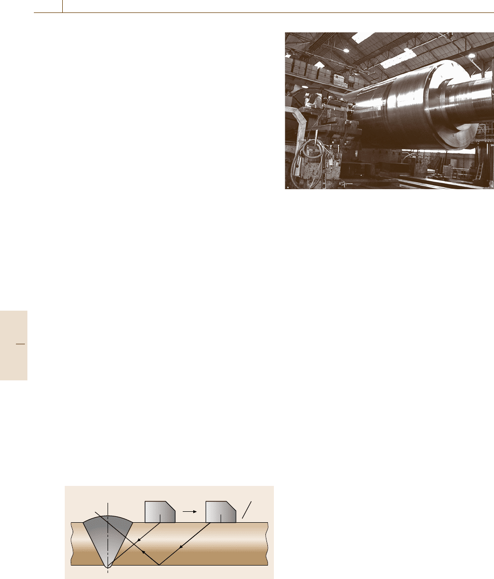
carried out using mechanized testing. Figure 16.18
shows an example of the examination of a turbine shaft
with a diameter of about 2 m. The examination was
performed using phased array probes [16.16]. During
the shaft rotation the incidence angles for longitudi-
nal waves were changed in a range between −30
◦
and
30
◦
with steps of 3
◦
. For every full circle a echotomo-
gram was reconstructed. After the whole examination
of the shaft the defect situation in the shaft, in the ra-
Part D 16.1
Performance Control 16.1 Nondestructive Evaluation 897
Phased array probe Phased array probe
Disc breakWheel
Fig. 16.19 Railway axel inspection with phased array
probes
dial and axial directions, was visualized with the help
a computer program called glassy shaft.
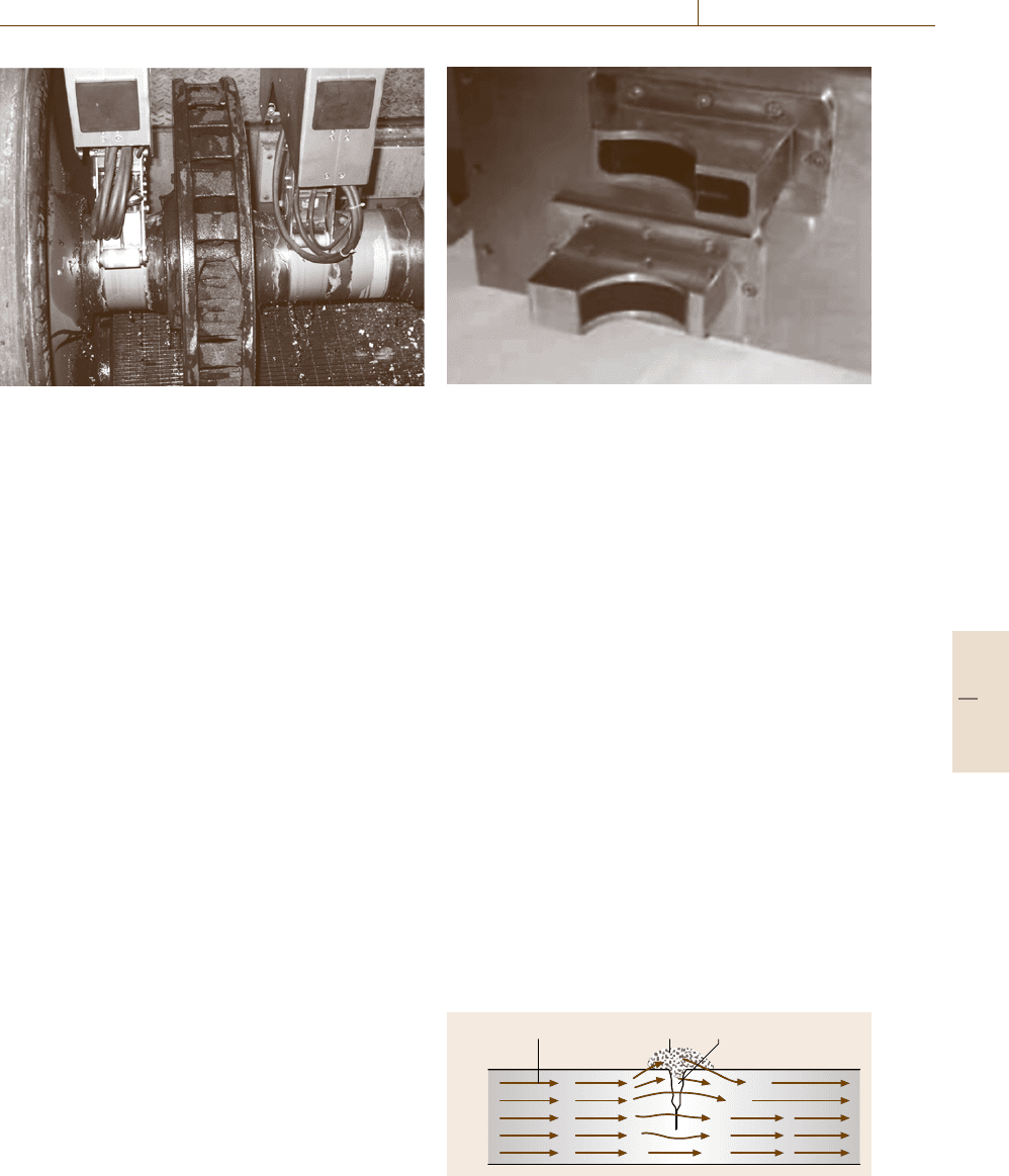
Another example where mechanized testing is used
is the inspection of railroad axels with phased array
probes (Fig. 16.19). Two coupled phased array probes on
the axel surface are presented in the figure (two probes
for each side). Thus for this special application case
four phased array probes are necessary for the examina-
tion of the area beneath the wheels and the disc brakes.
Phased array probes with the possibility of steering the
incidence angle have advantages because of the limited
accessibility between the wheel and the disc brake.
Inspection
of Semi-finished Industrial Products
AwidefieldforNDT is the inspection of semi-finished
products such as rods, pipes plates, casting products
etc. Defects in this group of products can either be on
or near the surface and internal (embedded) defects.
In the case of steel rods, manual ultrasonic inspec-
tion using the pulse-echo technique is implemented in
practice as well as mechanized inspection. Straight and
angle beam probes are for the detection of the different
defects such as shrinking cracks, inclusions, cavities,
pores etc. There are several different techniques for
identifying defects, which can be achieved by mecha-
nized inspection. One main difference is the handling
of the rod during the inspection, e.g. whether only lon-
gitudinal movement or rotation of product is performed.
The probe arrangement will depend on the type of me-
chanical rod movement that takes place. A more or less
simple movement of the rod can be carried out if phased
array probes or real-time scanners are used. The reason
Fig. 16.20 Array transducers for the examination of longi-
tudinal welds in pipes (GE Inspection Technologies)
is, that a complicated mechanical movement is substi-
tuted by the sound movement. One example of such
a transducer arrangement is presented in Fig. 16.20.
The geometry of the array transducer is adapted to
the geometry of the pipe to be inspected. In this case
the longitudinal weld of pipes will be examined. In
addition with the help of some of ultrasonic transduc-
ers a simple mechanized movement of a rod is also
possible. Three probe holders in a circumferential po-
sition of 120
◦
in each and the combination of angle
and straight-beam transducers sufficiently guarantee the
detection of embedded and near-surface longitudinal
defects.
16.1.4 Magnetic Particle Inspection
The physical principles of magnetic particle inspection
have been well known for a long time. At the begin-
ning of the 20th century it was discovered that, when
steel parts are machined while held in a magnetic chuck,
the iron grindings formed patterns around cracks on the
surface. The disturbance of magnetic fields by surface
defects in magnetized ferromagnetic specimens is the
Magnetic field Iron powder Crack
Fig. 16.21 Principle of magnetic particle inspection
Part D 16.1
