Czichos H., Saito T., Smith L.E. (Eds.) Handbook of Metrology and Testing
Подождите немного. Документ загружается.

958 Part D Materials Performance Testing
R
i, min
(%)
Lifetime ratio t
test
/L
dem
30
90
80
70
60
50
40
30
20
10
100
0
n =2
n =3
n =5
n =7
n =1
n =10
21.510.5 2.5
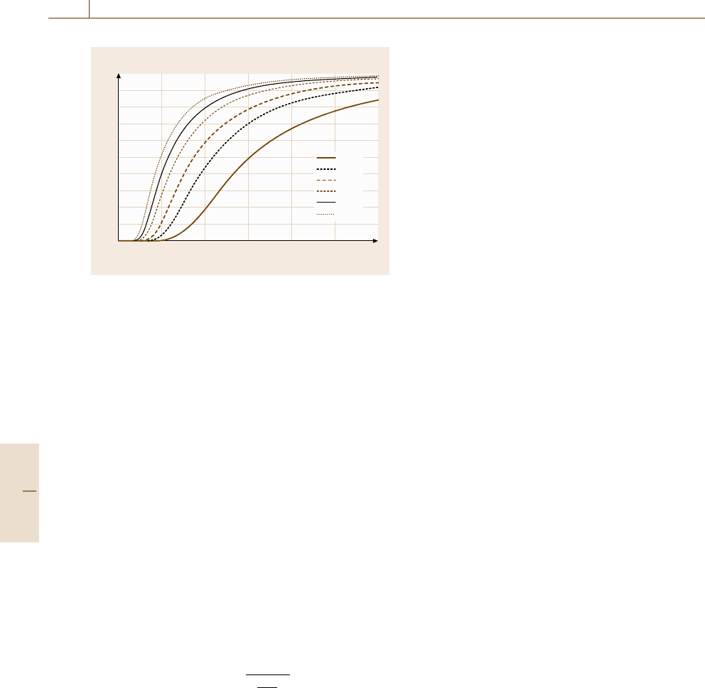
Fig. 16.108 Guaranteed least reliability R
i,min
of a device
tested in a success run as a function of the lifetime ratio
and of the number of samples n. The figure indicates that
with smaller sample number the testing time must increase
in order to maintain the same reliability level. It is helpful
in practice to know the rule of thumb that a reliability of
90% can be guaranteed when three test specimen survive
2–2.5× the demanded lifetime
Case (c) All Items Still in Function – Success Run. The
success run has become one of the major tools in re-
liability engineering. This is because it combines the
number of test specimen and the testing time. Addi-
tionally, the meaning of the confidence interval α for
reliability estimation becomes most obvious in this kind
of test.
The typical task is the following. We have to guaran-
tee a minimum reliability R
i,min
foradeviceatagiven
demanded lifetime L
dem
. To do so, we have a limited
number of specimens (e.g. n = 3) which we test for
a time t
test
.
If we assume the basic population to be Weibull dis-
tributed, then the formula for this test reads as follows:
R
i,min
(L
dem
) =(1−α)
⎡
⎢
⎣
1
n
t
test
L
dem
β
⎤
⎥
⎦
. (16.58)
For the derivation of this expression see [16.105]. It’s
meaning is that, if n components survive a reliabil-
ity test of duration t
test
> L
dem
, then we can guarantee
a minimum reliability R
i,min
of the device at the de-
manded lifetime L
dem
at a confidence level of α.
In practice, it is often the case that a confidence
level as well as the least guaranteed reliability at
the demanded lifetime are given. From (16.56), we
can calculate the necessary number of specimen and
the corresponding testing time which is necessary to
confirm that the given reliability can be guaranteed.
This important result is seen in Fig. 16.108 where the
least guaranteed reliability is plotted as a function of
the so-called lifetime ratio t
test
/L
dem
and the sample
number.
The main drawback of the test is that the Weibull
parameter β must be known in advance. It cannot be
determined using this method. It must be known from
experience, similar studies or from tests under simpli-
fied conditions.
Degradation Tests
Degradation testing is a rather new method that has re-
cently attracted many researchers [16.126, 127]. This
kind of testing is possible if there is a parameter that
can be measured during the operating time of the de-
vice and which indicates the degradation process. The
plotting of the parameter versus the lifetime describes
the so-called degradation path. As an example, the abra-
sion of a car tyre can be measured during a test and
plotted versus the driven kilometers. From the data
points we can extrapolate to longer lifetimes and es-
timate the time when the abrasion reaches a critical
value. The extrapolation data from n devices tested re-
sult in n lifetimes that can be analyzed with Weibull
as described before. The benefit is that the test can be
truncated at a time much smaller than the expected life-
time. Some research is ongoing on how long a device
must be tested until the extrapolation becomes good
enough [16.128].
Example. A ferroelectric memory chip can distinguish
between logic 1 and 0 if the polarization states P(N)
after N polarization reversals (cycles) do not fall be-
yond 80% of the initial value P
0
. P(N)/P
0
= 80%
is therefore the failure criterion of the device. Let
us assume a cycling test with four samples was car-
ried out, where P(N) is measured after a discrete
number of cycles. In order to save time, the mea-
surements are truncated after 10
8
cycles, although
the failure criterion is not reached. From the liter-
ature, it is known that P(N) is related to N by
P(N)/P
0
= exp(−N/N
∗
) +C, where N
∗
and C are
constants [16.129]. This model can be fitted to the data
points and extrapolated to higher cycle numbers than
10
8
in order to find the lifetimes L
i
where the fail-
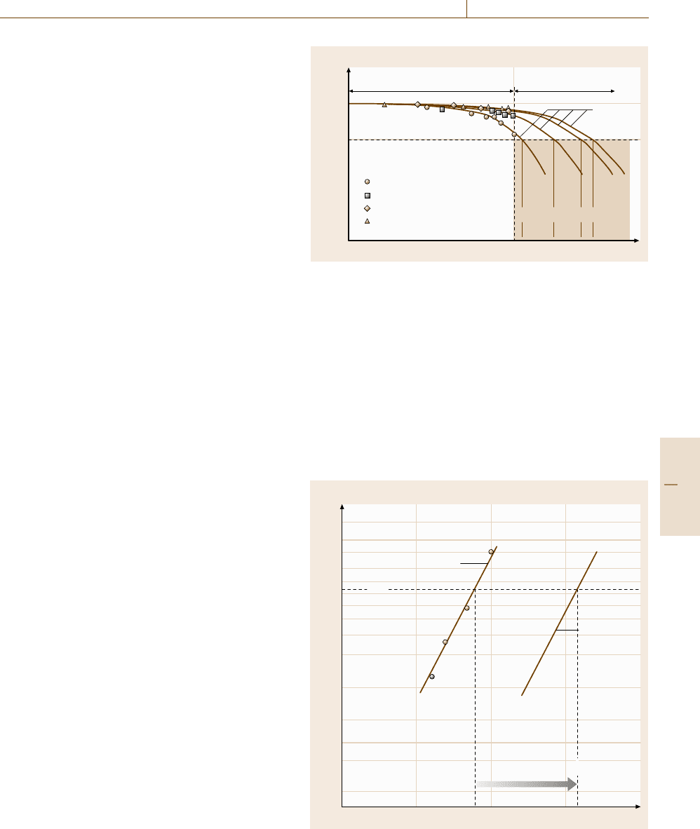
ure criterion is fulfilled (Fig. 16.109). With L
i
given,
a Weibull analysis may be performed as already de-
scribed in Sect. 16.7.2.
Part D 16.7
Performance Control 16.7 Characterization of Reliability 959
Fig. 16.109 Degradation test. Four devices were tested and
the data were extrapolated to the critical failure value of
80% remaining polarization. The lifetime data can now be
analyzed by means of the Weibull analysis
16.7.4 Accelerated Lifetime Testing
Accelerated lifetime testing (ALT) is a frequently used
method for reducing test time. Many publications deal
with the special problems arising from this proce-
dure [16.130].
The basic idea of an accelerated lifetime test is
to apply higher stresses to the device than it experi-
ences under real service conditions in order to provoke
a reasonable number of failures within a reasonable
time. Here, stress means any physical process that
influences the lifetime of the device; it may be me-
chanical stress, electrical voltage, current, temperature,
humidity and so on. New questions arise from this
procedure.
•
By what factor do the higher stresses accelerate the
degradation process? How are higher stresses and
shortened lifetime physically related?
•
In how far do higher stresses influence the failure
mode? Will higher stresses produce failure modes
that would not have occurred under normal condi-
tions?
In ALT it must be assured that the observed failures at
higher loading originate from the same failure mech-
anism that would be expected under use conditions in
practise. A proof for this is the following rule.
•
Failures that origin from the same failure mecha-
nism show the same shape parameter in the Weibull
net, and therefore are shifted parallel to each other.
They only differ in their lifetime, which is shorter
for higher stresses (Fig. 16.110).
•
Only the lifetime L of the device, which may be
expressed by any parameter related to the dis-
tribution (MTTF, η, B
10
, ...) is affected by the
acceleration.
Fig. 16.110 The Weibull line obtained from measurements
at higher stress is transferred to the Weibull line that would
have been achieved from experiments at use stresses by
multiplying the lifetime (here the characteristic life) by an
acceleration factor κ. The Weibull parameter β is assumed
to remain constant if the failure mode is the same at both
stress levels
P(N)/P
0
L
1
L
2
L
3
L
4
100 %
80 %
Cycles, log N
Measured Extrapolated
Failure criterion
Model
equation
Device 2
Device 3
Device 1
Device 4
10
8
Analysis Procedure
The acceleration is measured by the ratio by which the
lifetime is shortened by applying a higher stress. This
number is called the acceleration factor.
Let us assume that we can calculate the time to fail-
ure L from a model equation L(S), where S is the stress
level applied to the item. L(S) is the functional de-
scription of the dependency of the lifetime on the given
physical quantity.
Now let us assume that we test the device at two dif-
ferent stress levels with S
acc
> S
use
. (where “acc” stands
for acceleration, and “use” means the normal use con-
Failure probability F(t) (%)
99.9
99
95
90
50
63.2
10
5
3
2
1
η
use
= κη
acc
Lifetime (log)
β
use
= β
acc
Projection to
low stresses
(use)
Data measured
at high stresses
(acc.)
Part D 16.7

960 Part D Materials Performance Testing
dition of the device) Then we define the acceleration
factor κ as follows
κ =
L(S
use
)
L(S
acc
)
. (16.59)
The basic rule for how an accelerated reliability
test is to be performed can be summarized as follows
(Fig. 16.110).
•
Step 1: Collect failure data at higher stresses S
acc
.
•
Step 2: Perform a Weibull analysis as described in
Sect. 16.7.2.
•
Step 3: Calculate the lifetime at normal use condi-
tions by applying a suitable physical model describ-
ing the acceleration. Those acceleration models are
described below.
Acceleration Models
Using acceleration models, the mechanistic origin of the
acceleration is described. For any accelerated lifetime
testing, this is a crucial point at which the validity of the
whole test is decided. Two basic problems arise at this
point
•
In most cases, the physical model must be known
from preknowledge on the physical origin of the ob-
Table 16.12 Commonly used acceleration models, with their applications, model equations and acceleration factors.
These and further models can be found in [16.109]
Model Application Model equation Acceleration factor
Arrhenius Failure mechanisms that
depend on chemical
reactions, diffusion
processes or migration
processes. It covers many
of the nonmechanical
(or nonmaterial fatigue)
failure modes that cause
electronic equipment
failure
L(T ) = A exp
ΔH
k
B
T
T: temperature (K)
A: constant
k
B
: Boltzmann constant
ΔH: activation energy
of the process (must be
known in advance)
κ
T
=
L(T
use
)
L(T
acc
)
=exp
ΔH
k
1
T
use
−
1
T
acc
Inverse
power law
(IPL)
Stresses which are non-
thermal in nature; in most
cases the stress is given to
be electrical voltage, e.g.,
capacitors often follow the
IPL relationship
L(U) = AU
−b
U: driving voltage of the
device
A: constant
b: characteristic exponent
κ
U
=
U
use
U
acc
=
U
acc
U
use
b
Coffin–
Manson
Mechanical failure, ma-
terial fatigue or material
deformation, crack growth
in solder and other metals
due to repeated tempera-
ture cycling as equipment
is turned on and off
Δε
P
N
c
f
= A
Δε
P
: plastic strain ampli-
tude (peak–peak)
N
f
: number of cycles to
fail
c: cycling exponent (must
be known in advance)
A: material constant
κ
Δε
=
N
f
(Δε
use
)
N
f
(Δε
acc
)
=
Δε
acc
Δε
use
1
c
served failure. It is not sufficient to adjust model
equations to the given failure data.
•
Physical models contain parameters (such as the ac-
tivation energy, for instance; see below) that have to
be estimated or known from the literature. In a few
cases only these parameters can be calculated from
the failure data directly.
In the following Table 16.12, some of the common ac-
celeration test models are discussed in order to show
the principle. Here, we restrict the discussion to the
Arrhenius, the inverse power law (IPL) and the Coffin–
Manson model.
Advanced Acceleration Techniques
In recent years, some acceleration methods have arisen
that differ markedly from the scheme above sketched.
In particular, the highly accelerated lifetime testing
(HALT) and highly accelerated stress screening (HASS)
methods have gained increasing attraction in the near
past.
The goal of these methods is to find weaknesses
of a product at an early stage of development, e.g. for
a prototype, rather than predicting the lifetime of the
device.
Part D 16.7
Performance Control 16.7 Characterization of Reliability 961
We will mention these methods in brief here, and
recommend the papers referred to in [16.131] for further
information on this topic.
Step Stress Profile Testing. In this test, test specimens
are first subjected to a given level of stress for a certain
period of time, and are then subjected to a higher level
of stress. The process continues at increasing levels of
stress, until either all the specimens fail, or the time pe-
riod at the maximum stress level ends. The advantage
of this method is, that failure modes are provoked, how-
ever, with this technique it is very difficult to model the
acceleration properly [16.131].
It is mainly used for defining the operating envelope
of a product and as a possibility to compare variants in
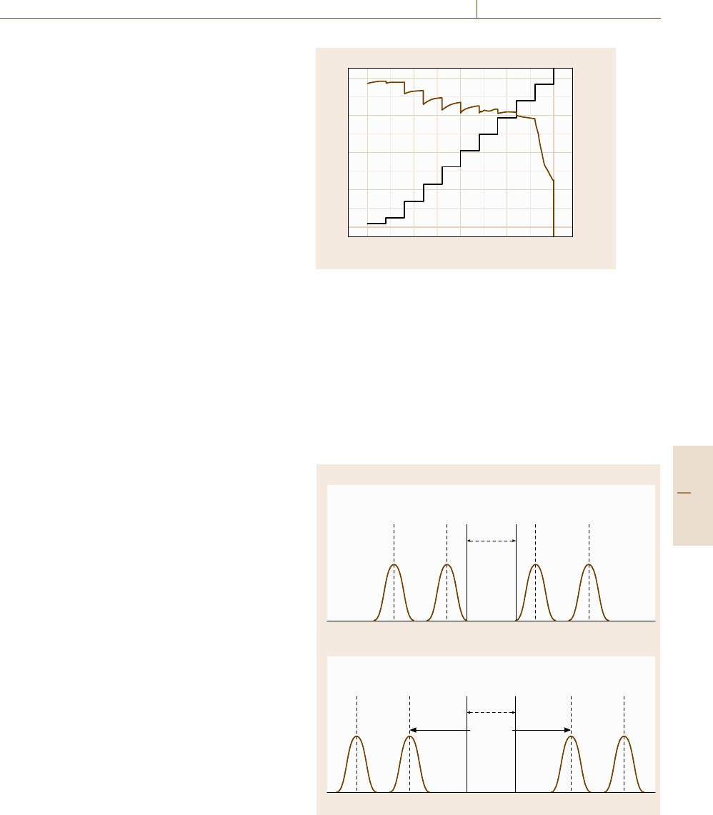
a short period of time. An example for a step stress of
a semiconductor transistor (in this case a high-electron
mobility transistor) is shown in Fig. 16.111 [16.132].
In this case the drain voltage (black line) of the tran-
sistor is increased stepwise nearly every 100 min until
80 V. At ≈60 V the gate current (brown line) excess
100 μA rapidly leading to a catastrophic degradation of
the device.
HALT (Highly Accelerated Lifetime Testing). HALT is
an development test with the intention to detect weak
spots in a system within a short time using a small
number of samples.
The main motivation of HALT is not the survival of
the product under specified conditions but to provoke
the product/system to fail and detect dormant defects
and provide the opportunity to improve reliability of the
product. This method should be performed at the begin-
ning of a product development as soon as a prototype
is available so that redesign efforts are still affordable.
A generalised illustration of the goal behind using HALT
is shown in Fig. 16.112 [16.133]. The upper part shows
the limits of a prototype before performing HALT. The
abscissa represents the stress (vibration, temperature,
voltage, etc.) the specimen is subjected to. The black
continuous lines indicate the operational area defined
by the product specifications. The inner dotted lines
represent its operational limits, at which the device re-
mains in a state of operation and at which any further
increase in stress will cause a recoverable failure. The
outer dotted lines represent the destruction limits, mean-
ing that a stress exceeding these limits will destroy the
device. By subjecting the specimen to increasing stress
levels of temperature and vibration (independently and
in combination) and other stresses specifically related to
the product beyond operating conditions, it is possible
Gate current (μA) Drain voltage (V)
Time (h)
20151050
100
200
300
0
400
60
40
20
80
0
Fig. 16.111 On-Wafer Step-Stress-Tests until catastrophic
degradation of a semiconductor transistor. The drain volt-
age (black line) of the transistor is increased stepwise nearly
every 100 min until 80 V. At ≈60 V the insulating fails and
thegatecurrent(brown line) excess 100 μA rapidly leading
to a catastrophic degradation of the device (after [16.132])
to determine the above-mentioned functional operating
and destructions limits, multiple failure modes and root
causes. Based on the obtained results improvements of
Lower
destruct
limit
Lower
oper.
limit
Upper
oper.
limit
Product
operational
specs
Operating
margin
After HALT
Stress
Upper
destruct
limit
Lower
destruct
limit
Lower
oper.
limit
Upper
oper.
limit
Product
operational
specs
Prior to HALT
Stress
Upper
destruct
limit
Fig. 16.112 An illustration of the enhanced operating limits due to
HALT (after [16.133])
Part D 16.7
962 Part D Materials Performance Testing
Vibration (g rms) Temperature (°C)
Time (min)
1007550250
30
20
0
10
50
40
–10
50
0
–50
150
100
200
–100
d)
Vibration (g rms) Temperature (°C)
Time (min)
806040200
30
20
0
10
50
40
–10
26
24
22
30
28
32
20
c)
Temperature (°C)
Time (min)
806040200
50
25
–25
0
100
75
–50
b)
Temperature (°C)
Time (min)
200150100500
50
0
100
–50
a)
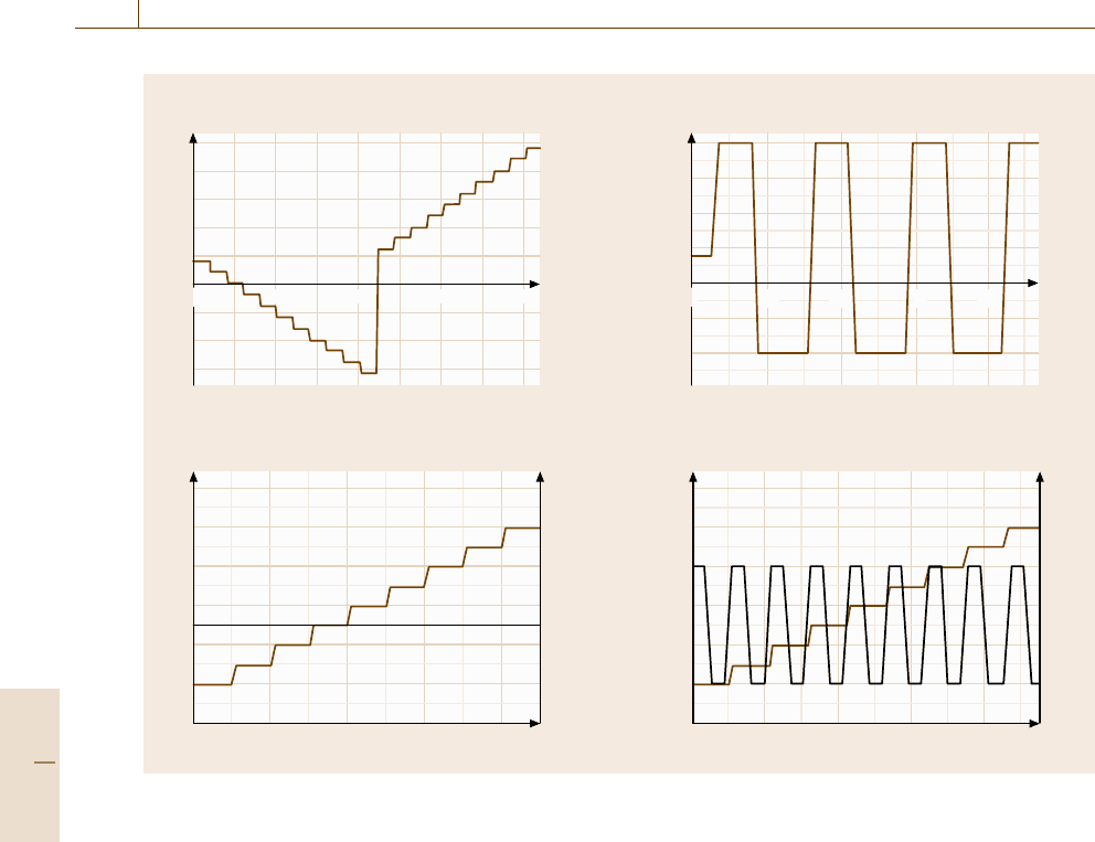
Fig. 16.113a–d An exemplary overview of possible tests including temperature and vibration loads
the prototype are carried out, leading to a higher ro-
bustness of the prototype shown in the lower part of
Fig. 16.112. The prototype shows an increased opera-
tional area and the operation and destruction limits are
shifted to higher levels.
Figure 16.113 shows an exemplary overview of dif-
ferent tests, which can be used for HALT. Graph a
shows a temperature test, in which the temperature is de-
creased and later increased stepwise overthe time. Graph
b shows rapid thermal transitions causing rapid expan-
sion and contraction of the prototype. Graph c illustrates
a test, in which the acceleration levels of the random vi-
bration are increased at a constant temperature. In the
last graph d two loads are combined, in this case increas-
ing vibration levels and rapid thermal transitions.
The obtained results can also be used later for HASS
(see below). Complaints with HALT are the inability of
reproducing failure modes because of the random nature
of HALT tests and the inability to predict the reliability
based on statistical data.
HASS (Highly Accelerated Stress Screening). HASS
is a form of accelerated environmental stress screening
and it is used for screening in the production process de-
tecting weak products and changes in the manufacturing
process. Samples of product assemblies are exposed to
all stresses simultaneously for a very limited time pe-
riod. The level of stresses can exceed beyond operating
limits and near destruct limits obtained by HALT before-
hand. These levels were predefined in a process called
Proof-of-screen (POS) with the goal that HASS detects
relevant defects without removing too much life from the
test items. By passing HASS successfully, it is possible
to ensure that a product has passed its infancy (see bath-
tub curve region 1) before being delivered to a customer.
These and further information can be found in [16.134].
16.7.5 System Reliability
In many practical cases, a system is manufactured from
several single components. The reliability R
S
of the
Part D 16.7
Performance Control 16.7 Characterization of Reliability 963
whole system depends on the reliability of the single
components R
i
.
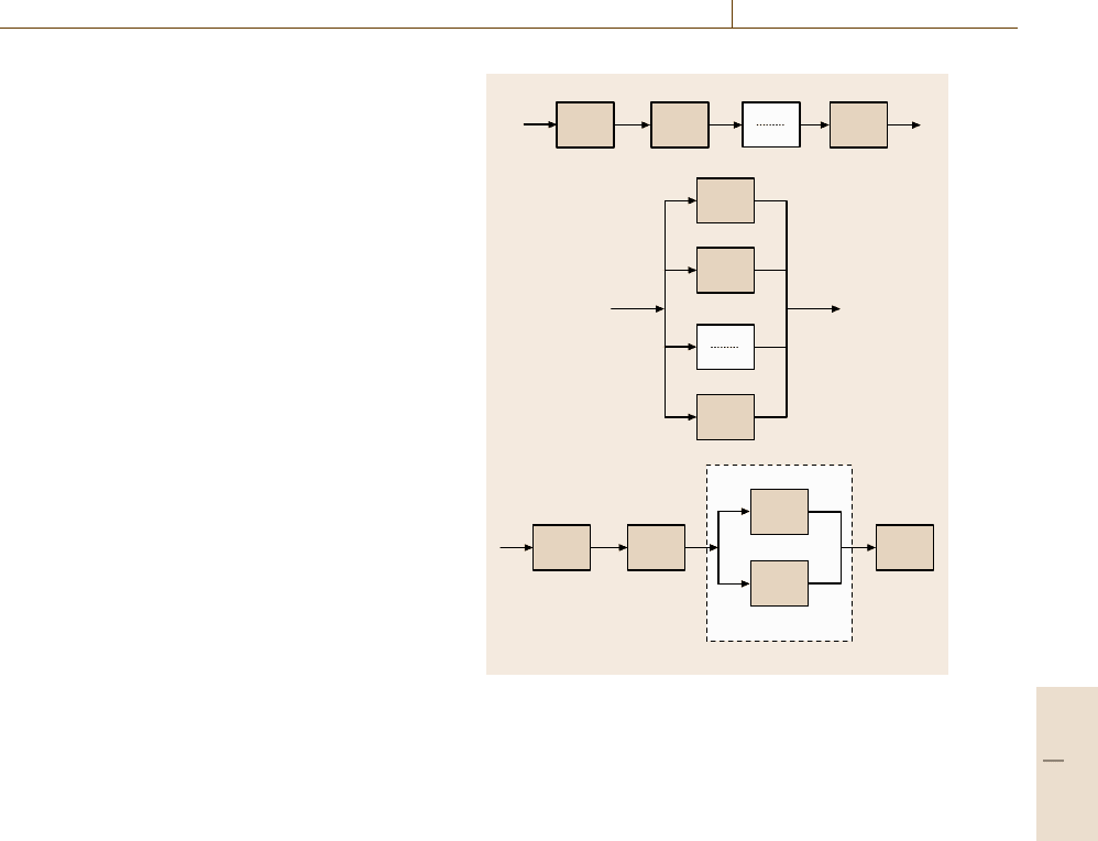
Serial Systems
In practice, it is often the case that the system’s func-
tionality depends on the component functionality such
that a failure of any component means a failure of the
whole device. For example, the system reliability of
a car depends on the reliability of the tyre as well as
on the engine. From this example, we see that the com-
ponents do not necessarily need to interact with each
other directly.
The underlying system structure can be inter-
preted as a serial system structure, which is shown in
Fig. 16.114a.
For a serial system, the reliability of the system at
a given time t is calculated to be the product of the re-
liabilities of the components, what follows from basic
rules for probability calculations:
R
S,serial
(t) = R
1
R
2
...R
n
=
i
R
i
(t) (16.60)
or, by using F
S
=1−R
S
and F
i
=1−R
i
F
S,serial
(t) =1−
i
[1−F
i
(t)]. (16.61)
From these relations, we can draw some important con-
clusions
•
the more components with given reliabilities, the
smaller the system reliability becomes;
•
in order to maintain a high reliability of the system,
the reliability of the components must be improved;
•
the system cannot be better than the worst compo-
nent.
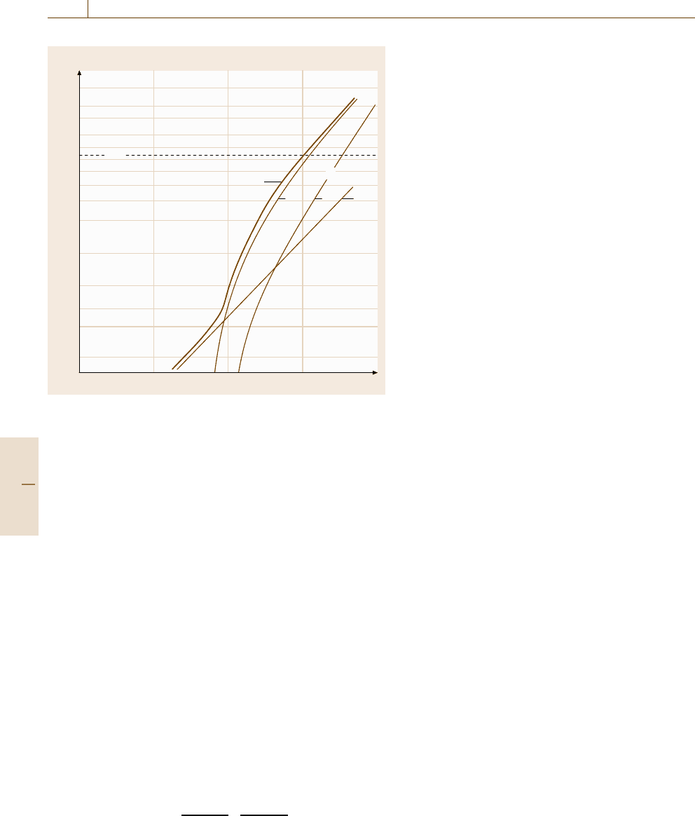
The reliabilities of the components as well as the sys-
tem reliability can be visualized in a Weibull plot.
In Fig. 16.115 we see this for the case of a three-
component system. The thick line represents the
Weibull distribution of the whole system as a result of
the multiplication rule introduced above.
From this plot, we find further interesting facts.
•
The system Weibull line is always located towards
lower lifetimes. (This is identical to the above state-
ment that the system has a lower reliability than the
components.)
•
Due to the sensitivity of the system reliability to
the component reliability, it makes a significant
difference if we use the two- or three-parameter
R
n
R
1
R
2
R
n
R
1
R
2
R
1
R
2
R
5
R
3
R
4
Parallel subsystem
a)
b)
c)
Fig. 16.114 (a) Serial system; (b) parallel system; (c) com-
bined system
Weibull distribution for the components. If the
two-parameter distribution is used although a three-
parameter distribution is justified, then the failure
probability is overestimated. This leads to an
over-dimensioning of the device. Especially in me-
chanical engineering, where the strength of a device
is dependent on the material amount, this plays an
important role from an economical and ecological
point of view [16.135].
Parallel Systems, Redundancy
If the system contains components that are able to ful-
fil the same functionality as other components, then the
system contains redundancy. In the system structure,
those components are represented as parallel structures,
asshowninFig.16.114b.
In contrast to a serial system, additional redundant
components increase the reliability. This is also indi-
cated in the system equations for parallel systems where
the failure probabilities F(t), rather than the reliabili-
ties, are multiplied
F
S,parallel
(t) = F
1
F
2
...F
n
=
i
F
i
(t) (16.62)
Part D 16.7
964 Part D Materials Performance Testing
Failure probability F(t) (%)
99.9
99
95
90
50
63.2
10
5
3
2
1
Lifetime (log)
ABC
System
Components
Fig. 16.115 The reliability of a system as a result of the reliabili-
ties of its components, here for the example n = 3 and for a serial
system. We see that the system reliability is always lower than the
reliability of the weakest part. In this example, the system reliability
is dominated either by component C or A, depending on the region
of the failure probability. Component B, on the other hand, has mi-
nor influence since it is more reliable than the others in the whole
region
or, expressed in terms of the reliability functions R
i
(t) =
1 −F
i
(t)
R
S,parallel
(t) =1 −[(1 −R
1
)(1 −R
2
) ...(1 −R
n
)]
=1 −
i
[1 −R
i
(t)]. (16.63)
Combined Systems
In practice, it is often the case that within a system some
components are in series and others are parallel. In this
case, the system reliability can be calculated from the
rules of Boolean algebra. A simple example will eluci-
date the principle.
In Fig. 16.114c we see the functional structure of
a system. The system reliability calculates as follows
R
S
= R
1
R
2
[
1 −(1 − R
3
)(1 −R
4
)
]
=parallel subsystem
R
5
. (16.64)
16.7.6 System Reliability Estimation
in Practice
Despite the fact that the theoretical background of
reliability engineering, as illustrated in brief in the
proceeding sections, is well defined, the application
of these tools in practice is far from straightforward.
There are several practical problems of which the fol-
lowing are the most prominent [16.136]: (a) systems
are tending to become more complex. (b) Mechanical,
electronic and software components are simultaneously
included in the functionality of systems, for exam-
ple X-by-wire techniques. Such mechatronic systems
will be one of the future challenges in reliability en-
gineering, which has also been documented by the
increasing number of publications in this field over the
last years [16.137].
In the following example, we will elucidate all
these problems by following the procedure in reliabil-
ity estimation as sketched above. We will show that all
above-mentioned problems will be addressed in this ex-
ample, giving a better understanding of the underlying
methodology. The example chosen here was subject of
a detailed reliability investigation performed by the au-
thors. We will refer to a previous publication [16.138]
where this work is already described in detail. The
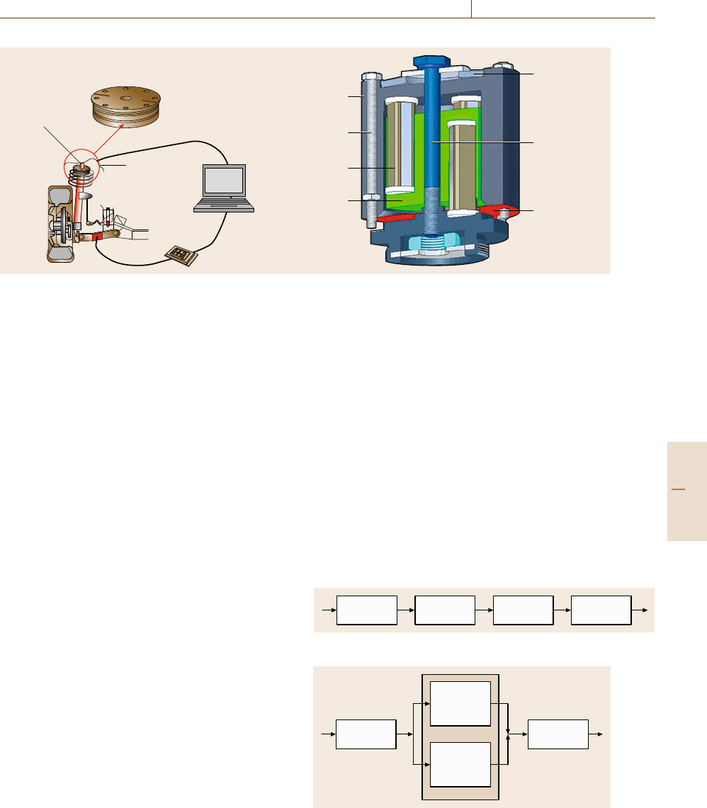
system to be investigated in our example is an active in-
terface (AI), which was designed for actively damping
unwanted vibrations as well as noise in an automobile,
Fig. 16.116 [16.139].
According to the above sketched procedure, the reli-
ability analysis was conducted following this sequence
of steps: i) System analysis, ii) Determination of com-
ponent reliabilities, iii) Determination of the system
reliability.
i) System Analysis
As already described above, the aim is to find the un-
derlying abstraction of the system structure according
to Fig. 16.114, which will be the basis for the later sys-
tem reliability calculation. To do so, the system was
subdivided into the following main subsystems.
•
Mechanics,
•
Electronics,
•
Actuators,
•
Control.
From a function analysis performed by the experts in
the field of the different technical domains, it became
clear that a failure of one of these subsystems will result
in a system failure. Furthermore, the analysis revealed
Part D 16.7
Performance Control 16.7 Characterization of Reliability 965
Housing
Active
interface
Prototype of the
active 3 DOF interface
Sensors for
vibration
detection
Housing
cascades
Tension spring
Tension screw
Thrust relief
Housing screw
Piezoelectric
actuator
a) b)
Fig. 16.116 (a) The active interface is located within the spring dome of a car. Sensors detect the unwanted vibrations,
the signals are transferred to a controller and a power unit, which drives the piezoelectric actuators acting against the
vibrations. (b) Inner construction of the active interface
that the failure behaviour in each subsystem is in large
parts independent of the failure behaviour of the others.
It must be stated that the determination of this indepen-
dence is by far not trivial, since in many practical cases
not all possible failure modes are known in advance. In
our case, a thorough failure mode and effects analysis
(FMEA) was performed prior to the reliability inves-
tigation, and so a broad knowledge on possible failure
modes was present [16.140]. The system structure of the
active interface is therefore given as a serial structure
showninFig.16.117.
The subsystems themselves were further analysed
in order to determine their reliability structure. For
instance, for parts of the mechanical construction
a combined structure (serial and parallel elements, com-
pare Fig. 16.114c was found as sketched in Fig. 16.118.
ii) Determination of Component Reliabilities
In this section, the determination of the reliabilities of
the aforementioned subsystems mechanics, electronics,
actuators and control will be described. It will be shown
that the underlying method is different in each domain.
Further more, state of the art within the domains also
widely differs. The main problem in daily practice is
that we need failure data of the components for the cal-
culation of system reliabilities following the schemes
sketched above. Those failure data – as we have outlined
in the previous sections – are not sufficiently repre-
sented by giving a lifetime of the device. Instead, the
failure behavior in the form of the Weibull parameters,
containing information about the average life and the
scatter, is needed. As already mentioned, these values
are not documented in public data bases. Exceptions
are failure rates for electronic devices and structural
durability data for metallic components [16.114].
Mechanics. The reliability of the construction of the ac-
tive interface is characterized by standard methods of
structural durability. For information and further refer-
ences see [16.114]aswellasChap.7 in this handbook.
Electronics. The determination of the reliability of elec-
tronic components is fixed in international standards.
One of the first standards in this field was the MIL-
Std 217 [16.141], another newer standard is the IEC
TR 62380 [16.142]. In both cases, a constant failure
R3
Actuators
R2
Electronics
R1
Mechanics
R4
Control
Fig. 16.117 Serial reliability structure of the active interface
R1.3
Bonding
R1.2
Threaded
connection
R1.1
Bias spring
R1.4
Shear relief
Fig. 16.118 Combined reliability structure of a part of the
subsystem mechanics
Part D 16.7

966 Part D Materials Performance Testing
rate for the electronic components is assumed, which
depends on the load conditions (temperature, moisture,
mechanicalvibrations,...).Thereliability of the whole
electronic subsystem is determined by addition of all
failure rates.
Actuators. Additional challenges arise from the fact that
mechatronic systems often include new materials that
serve as actuators or sensors. This class of materials is
called smart materials. These active materials, which
include ferro- and piezoelectric ceramics [16.143, 144]
and shape-memory alloys [16.145], exhibit failures
under long-term operation that are not well under-
stood despite intensive work over the last decades. In
particular, it is not understood which failures occur
under which service conditions (electrical, mechani-
cal stress, temperature, etc.), and the failure probability
functions under those service conditions are not yet
known.
The actuators used in the AI consist of piezoelec-
tric materials. Piezoelectric materials have been used
in the context of adaptronic systems for several years,
however, reliability data available from manufacturers
refer to service conditions from other applications like
fuel injection systems or micro positioning. It is there-
fore a challenging task to transfer the given reliability
data to the actual service conditions of the AI. This can
only be done by combination of expert judgement and
experimental tests where necessary.
Control. The controllers at one hand consist of elec-
tronic hardware, which was already described in the
previous section. On the other hand, it consists of
software components, which differ markedly from hard-
ware components with respect to their failure behavior.
Up to now, there is no general reliability model for soft-
ware available [16.146]. Present methods of software
reliability estimation, as e.g. described in [16.147,148],
are able to quantify implementation failures mainly. Im-
plementation failures origin from human programming
errors [16.149]. State of the art is the assumption of
a correlation between the amount of generated codes
and the amount of failures, which is, on the other hand,
not generally accepted [16.150]. A quantification of
specification errors is not possible at current state of the
art [16.149].
iii) System Reliability
Based on the information gained from the above de-
scribed procedure, it was possible to estimate the
Weibull parameters characteristic lifetime, Weibull
module and failure free time for the subcomponents
(compare Sect. 16.1.2).
Under the given preassumption, that the failure
behaviors of the subcomponents are independent, the
system reliability function of the AI reads, following
Sect. 16.1.5, as follows
R
Active interface
= R
mechanics
× R
electronics
× R
actuator
× R
control
. (16.65)
The system reliability function R
AI
is obtained from
multiplication of the component reliability functions ac-
cording to (16.65). In case of time-dependent failure
behavior, the analytical solution of the mutiplication
in these equations can only be solved by computa-
tion. This was done by means of the software package
SYSLEB, which was developed at the IMA (Institute
of Machine Components, University of Stuttgart) for
the purpose of conducting several analyses. SYSLEB
is a powerful software package to analyse life cycle
data using different distributions (e.g. Weibull, normal,
lognormal, exponential). Computation of Weibull dis-
tribution parameters including confidence limits as well
as extensive mathematic and graphic illustrations are
more SYSLEB-features used for this work. Maximum-
Likelihood estimation for combinations of several
distribution functions and Monte-Carlo-simulation are
further possibilities to use SYSLEB for analyzing sys-
tem reliability.
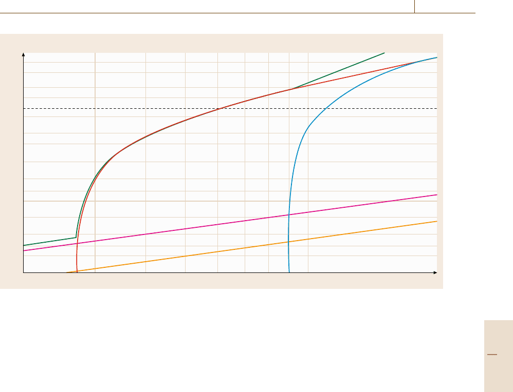
In order to visualize the Weibull lines for the system
reliability function R
AI
(t) as well as for the subcom-
ponents, the Weibull lines are plotted into a Weibull
diagram, what is also a feature of the SYSLEB soft-
ware tool, Fig. 16.119. As can be seen, The Weibull
lines for the components actuator (red), bias spring
(blue), controller (magenta), amplifier (yellow) as well
as the resulting system reliability line (green) are shown
in one graph according to the schematic drawing in
Fig. 16.115.
For the electronic components like controller and
amplifier, a constant failure rate was assumed, what
is typical of electronic components. In the Weibull
plot, this is expressed by a straight line. The other
components were assumed to have a wear-out fail-
ure behavior with a given failure-free time. As can
be seen from the plot, the system reliability curve
at lower lifetimes depends on the failure behavior of
the electronic components. However, after reaching the
failure free time of the actuators, the actuators start
to dominate. Only after very long lifetimes, the bias
spring gives a significant contribution to the system
reliability function. As can be seen from the Weibull
Part D 16.7
Performance Control 16.A Appendix 967
Failure probability F(t) (%)
99.9
99.0
90.0
80.0
50.0
30.0
20.0
10.0
5.0
63.2
3.0
2.0
1.0
0.3
0.5
0.2
0.1
Lifetime (t)
Fig. 16.119 Weibull plot of the components actuator (red), bias spring (blue), controller (magenta), amplifier (yellow)as
well as the resulting system reliability line (green) (after [16.138])
plot, an improvement in the reliability of the actu-
ators will have the greatest impact on the system
reliability.
The example shows, how a quantitative reliability
estimation of a complex system can be performed by ap-
plication of the Weibull distribution and Boolean system
theory.
It also shows that there are several preconditions to
be met. On system level the interactions of the com-
ponents must be understood at a depth allowing for
a judgement of the independence of the components,
which is a necessary precondition for the applicability
of the above sketched procedure.
Furthermore, knowledge about the failure behaviour
of the components must be available for the analysis. At
this point, the quality of the available data is most cru-
cial. The general experience is that the data available
do not allow a straightforward introduction to the sys-
tem reliability analysis without prior interpretation of
the available data and without prior expert judgement.
The availability of lifetime data of high quality will
be a main challenge in reliability engineering in the
future.
16.A Appendix
In the following table, the median rank regression for
the 5, 59 and 95% percentiles of the failure probabil-
ity F (in %) are listed for sample sizes from n = 3up
to n = 12. The values are of interest for the Weibull
analysis introduced in Sect. 16.7.2.
Part D 16.A
