Czichos H., Saito T., Smith L.E. (Eds.) Handbook of Metrology and Testing
Подождите немного. Документ загружается.


718 Part D Materials Performance Testing
to be considered in addition to the hydrogen content.
A tensile test cannot always prove the embrittling ef-
fects of hydrogen caused by diffusion processes. With
high strain rates hydrogen-charged samples show nearly
the same reduction of area as samples free of hy-
drogen. It is only at very low straining rates that
hydrogen results in brittle behavior. The reason for
this phenomenon is that with high deformation rates
not enough hydrogen can be provided to cause a brit-
tle fracture. Ductile behavior can be observed, i. e.
a minimum time period is necessary for crack initiation
and crack propagation of a critical length [12.74, 86].
Fractography can provide proof of hydrogen embrittle-
ment even in those cases where there are only slight
changes in mechanical properties. Undeniable indica-
tions can be found in the surface area of the crack
breakthrough. Hydrogen-embrittled quenched and tem-
pered steels always have an intergranular crack zone.
This is clearly different from the behavior of notch-
based brittle fractures or ductile spontaneous fractures.
Apart from the crack area the other parts of the
fracture surface could look like notch-based brittle
fractures.
12.7.5 Test Methods
For testing the susceptibility of a material against
hydrogen-induced stress corrosion cracking or deter-
mining the effect of specific environmental conditions
on a metal with regard to hydrogen embrittlement
all test methods previously described in Sects. 12.5
and 12.6 are applicable. In addition to these tests also
the uptake of hydrogen in an electrochemical cell which
has been proposed by Devanathan can be investigated
and the data evolved may be used for determining the
diffusion coefficient of hydrogen in a metal or, if the dif-
fusion coefficient is known, provide data on hydrogen
activity at the surface of the metal.
12.8 High-Temperature Corrosion
In industrial high-temperature applications corrosion is
a major life-limiting factor for in-service components.
Such applications are e.g. fossil-fuel power stations,
petrochemical and chemical plants, exhaust ducts, land
based gas turbines and jet engines, etc. There exist
a number of tests aiming at evaluating the effect of
the high-temperature environment on material perfor-
mance for the different applications that in most cases
are laboratory tests, although some field testing may
also be performed. In the laboratory tests it is usu-
ally intended to simulate conditions which are close
to the industrial situation with regard to environment,
temperature and mechanical stresses. As the situation
in high-temperature applications in most cases is very
complex it is, however, not easy to simulate the actual
conditions on a one-to-one basis. Therefore most of the
high-temperature corrosion tests in the laboratory are
based on a simplification of the practical conditions or
on conditions leading to an acceleration of the test. In
the latter case it should, however, be kept in mind that
accelerated testing may lead to a change in the corro-
sion mechanism and, thus, possibly to misinterpretation
of the data for the material performance under practical
conditions. Furthermore extreme care should be taken if
the results of such accelerated laboratory tests are taken
for life time extrapolation.
12.8.1 Main Parameters
in High-Temperature Corrosion
Corrosion Testing
The basic principles for high-temperature corrosion
testing are relatively easy. Actually there are two types
of parameters which are usually measured. The first is
parameters related to mass change that results from the
reaction of the material with its environment by which
either a mass gain or a mass loss can take place. A mass
gain will occur if the reaction leads to the formation of
a solid corrosion product on the surface and/or in the
metal subsurface zone. Mass losses will occur when ei-
ther the solid corrosion product spalls from the surface
(e.g. oxide bits flake off the sample) or if volatile cor-
rosion products are formed which evaporate. Since the
mass change is proportional to the amount of species
from the environment taken up by the material in the ox-
idation reaction or to the amount of material evaporated
by formation of volatile corrosion products the high-
temperature corrosion kinetics can easily be determined
by continuous or discontinuous measurements of the
specimen weight or mass in tests. Such mass measure-
ments can of course also be performed with specimens
from field exposure so that it becomes possible to deter-
mine corrosion kinetics also in field testing.
Part D 12.8

Corrosion 12.8 High-Temperature Corrosion 719
In combination with mass measurements it is benefi-
cial and even necessary to characterize additional dam-
age parameters resulting from the corrosion process.
These parameters are determined by post-experimental
sectioning of the specimens in the metallography and
measurement of geometrical data on surface scale thick-
ness and on internal corrosion depth. Again this method
can also be applied to specimens from field testing. In
the present chapter it is intended to focus on laboratory
testing. Actually many of the aspects dealing with labo-
ratory testing (especially those on the evaluation of the
corrosion data) can also be applied to field testing. With
regard to the specific aspects of field testing, please refer
to [12.87].
12.8.2 Test Standards or Guidelines
Although high-temperature corrosion testing has been
performed in industry and scientific laboratories now
for almost a century there are very few guidelines or
standards describing the test procedures. In the follow-
ing the more important of these standards or guidelines
are listed.
•
ASTM G54Practice for simple static oxidation
testing [12.88]:
This standard covers the determination of the rela-
tive growth, scale, and microstructural characteris-
tics of an oxide on the surface of a pure metal or
alloy under isothermal condition in still air. This
standard was later withdrawn but is still regarded as
useful.
•
ASTM B76Method for accelerated life test of
nickel-chromium and nickel-chromium-iron alloys
for electrical heating [12.89]:
This standard covers the determination of the resis-
tance to oxidation of nickel-based electrical heating
alloys at elevated temperatures under intermittent
heating using a constant-temperature cycle test.
This test method is used for comparative purposes
only.
•
ASTM B78Method for accelerated life test of
iron-chromium-aluminum alloys for electrical heat-
ing [12.90]:
This standard covers the determination of the re-
sistance to oxidation of iron-chromium-aluminum
alloys for electrical heating at elevated temperatures
under intermittent heating similar to ASTM G 76.
This test is again used for comparative purposes
only.
•
ASTM G79Practice for evaluation of metals ex-
posed to carburization environments [12.91]:
This standard covers procedures for the identifica-
tion and measurement of the extent of carburization
in a metal sample and for the interpretation and
evaluation of the effects of carburization. It applies
mainly to iron- and nickel-based alloys for high-
temperature applications.
•
Draft code of practice: TESTCORR – Discontinuous
corrosion testing in high-temperature gaseous envi-
ronment (ERA report 2000-0546) [12.92]:
This draft code of practice, which is the result
of a research programme supported by the CEC
standards, measurements and testing programme
describes in detail the procedures for the deter-
mination of specimen wastage using mass and
dimensional change. A major consideration is the
traceability of the measurements and the validity
of the statistical treatment of the data generated.
These procedures have been developed in con-
junction with specimen preparation guidelines and
recommendations for a statistical analysis of the
data.
•
JIS (Japanese Institute of Standards) Z 2281-
1993 Test method for continuous oxidation test
at elevated temperatures for metallic mater-
ials [12.93]:
This Japanese standard covers one of the most often-
used tests in high-temperature corrosion. A tentative
translation from the Japanese manuscript into En-
glish is available from JIS.
•
JIS Z 2282-1996 Method of cyclic oxidation test-
ing at elevated temperatures for metallic mater-
ials [12.94]:
This standard covers another most often used high-
temperature corrosion test in industry and is also
available as a tentative translation from Japanese
into English.
•
EFC publication no. 14 Guidelines for methods of
testing and research in high temperature corro-
sion [12.95]:
This publication contains the papers of a workshop
on this topic organized by the working party on cor-
rosion by hot gases and combustion products of the
European Federation of Corrosion where all major
aspects of high-temperature corrosion testing were
addressed.
•
EFC publication no. 27 cyclic oxidation of high tem-
perature materials – mechanisms, testing methods,
characterization and life time estimation [12.96]:
Part D 12.8

720 Part D Materials Performance Testing
This publication is based on the papers presented
at a workshop of the same title again organized by
the aforementioned working party of the European
Federation of Corrosion. The workshop was solely
devoted to thermal cycling oxidation testing.
Especially at the last mentioned workshop with strong
international participation from around the world it was
stated that the situation with regard to standardization
of high-temperature corrosion testing is rather unsat-
isfactory at present. As a consequence two initiatives
were started. One was in the form a European research
project named COTEST [12.97] which aimed at the de-
velopment of a code of practice for a test method for
thermal cycling oxidation testing. The results of this
work have been published as a book [12.98]. The second
initiative was started by Japanese industrial researchers
aiming at the development of an ISO standard based
on the existing Japanese standards mentioned above.
A workgroup was formed in the ISO technical commit-
tee 156 (corrosion of metals and alloys) which has the
designation WG 13, high-temperature corrosion. The
aim of this work group is to develop ISO standards in
the following fields.
•
Thermogravimetric testing:
ISO work group definition: in situ mass measure-
ments at elevated temperatures on a single specimen
without intermediate cooling.
•
Continuous isothermal exposure testing:
ISO work group definition: single post-exposure
Table 12.4 Draft documents of ISO TC 156 WG 13 on high temperature corrosion testing to become international
standards
Title Voting Stage (as of July 2010)
ISO/NP 21608: Corrosion of metals and alloys –
Test method for isothermal exposure oxidation testing under high temperature
corrosion conditions for metallic materials
30.99 (CD approved for registration as DIS)
ISO/CD 13573: Corrosion of metals and alloys –
Test method for thermal cycling exposure testing under high temperature corrosion
conditions for metallic materials
30.20 (CD study/ballot initiated)
ISO/CD 26146: Corrosion of metals and alloys –
Method for metallographic examination of samples after exposure to high
temperature corrosive environments
30.20 (CD study/ballot initiated)
New documents (under work as of July 2010):
1 Corrosion of Metals and Alloys Test method for high-temperature corrosion testing of metallic materials by fully embedding in
salt, ash, or other inorganic solids
2 Corrosion of Metals and Alloys Test method for high-temperature corrosion testing of metallic materials by partially embedding
in salt, ash, or other inorganic solids
3 Corrosion of Metals and Alloys Test method for high-temperature corrosion testing of metallic materials by immersing in molten
salt or other inorganic liquids
4 Corrosion of Metals and Alloys Test method for high-temperature corrosion testing of metallic materials by coating with salt,
ash, or other inorganic solids
mass measurement on a series of specimens without
intermediate cooling.
•
Discontinuous isothermal exposure testing:
ISO work group definition: series of mass mea-
surements on a single specimen with intermediate
cooling at predetermined times not necessarily reg-
ular.
•
Thermal cycling oxidation testing:
ISO work group definition: series of mass measure-
ments on a single specimen with repeated, regular
and controlled temperature cycles.
•
General guidelines for a post-exposure examination:
No definition by the ISO work group.
In the development of these work items the knowl-
edge existing in the form of the national standards and
European guidelines mentioned above is being used.
This particularly concerns the results from the TEST-
CORR document and the COTEST document as well
as the Japanese standards. These ISO standards are
expected to be the first documents with international
acceptance in the field of high-temperature corrosion
testing. The current documents of ISO WG13 are listed
in Table 12.4. As these documents are still under devel-
opment, in the present chapter the most recent situation
with regard to the working drafts of these standards will
be taken into account. This chapter on high-temperature
corrosion testing, therefore, cannot yet rely on generally
accepted existing standards but the content will be pre-
sented in a way which is supposed to be compatible with
the future ISO standards.
Part D 12.8
Corrosion 12.8 High-Temperature Corrosion 721
12.8.3 Mass Change Measurements
Principles
The basic idea behind the mass change measurements
is to have an easy method providing information about
the oxidation or corrosion kinetics. This kinetics al-
low an assessment of materials performance from the
viewpoint of oxidation or corrosion resistance accord-
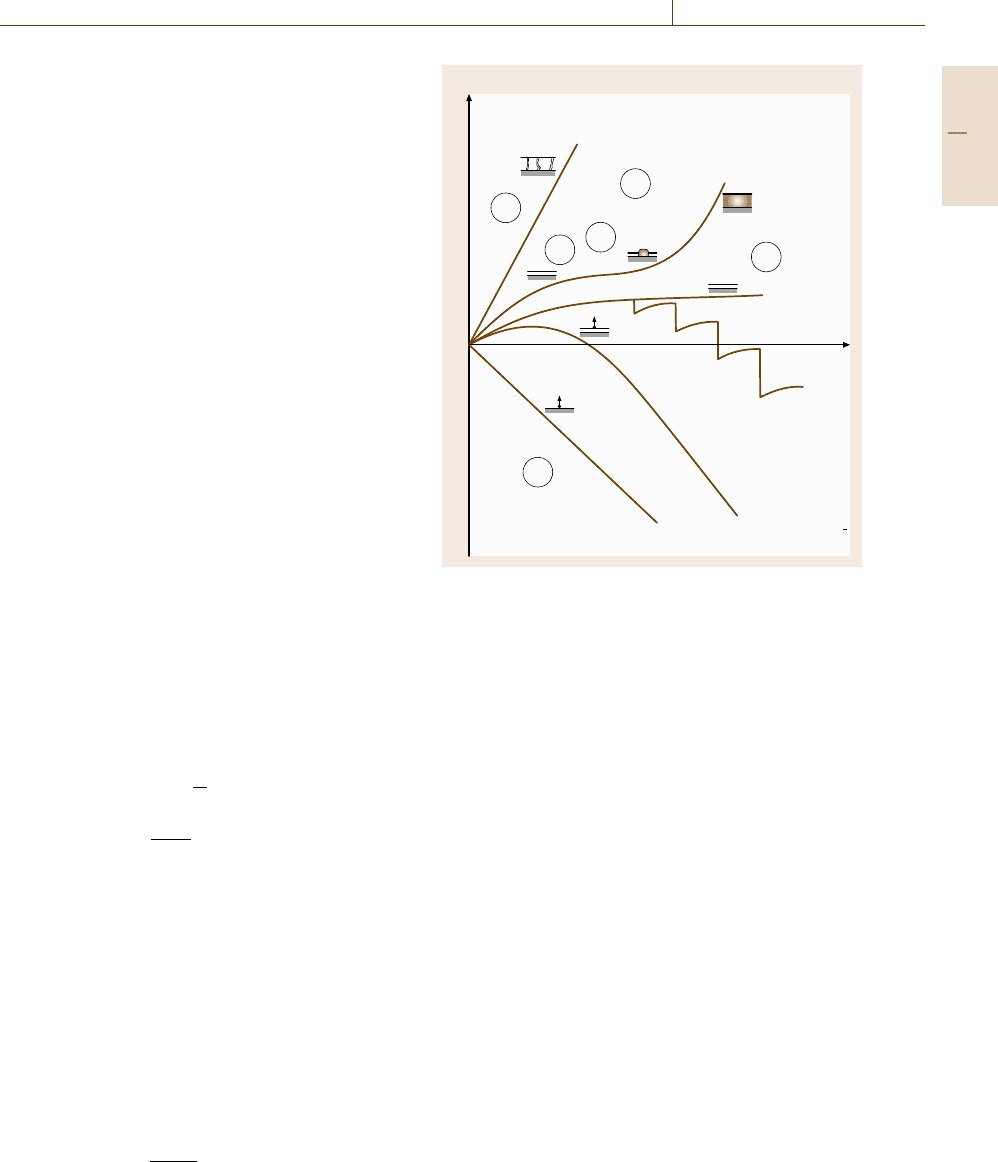
ing to the schematic representation in Fig. 12.48. The
ideal situation with regard to high-temperature corro-
sion resistance is the formation of a very thin and
dense protective oxide scale on the surface of the mater-
ial. This behavior is usually characterized by parabolic
kinetics with slow scale growth rates, i. e. the mass in-
crease or the increase of the oxide scale thickness follow
a parabolic time law
(Δm/A)
2
=k
p
t , (12.84)
where Δm is the mass increase, A is the specimen sur-
face area, k
p
is the parabolic oxidation rate constant and
t is oxidation time. A slow oxidation rate means that k
p
has a very low value. Equation (12.84) can also be writ-
ten in terms of the increase of the oxide scale thickness
according to
x
2
=k
p
t , (12.85)
where x is the oxide scale thickness. As in many cases
oxidation does not strictly follow a parabolic rate law,
(12.84)and(12.85) can also be written in the more gen-
eral form including the temperature dependence [12.99]
Δm/A =
[
k(T)
]
1/n
t
t
o
1/n
, (12.86)
k(T ) =k
o
e
−E
A
RT
(12.87)
with k(T) as a temperature-dependent oxidation rate
constant (for the parabolic case k(T) =k
p
), t
o
as the
time basis (e.g. 1 s if seconds are used for t), k
o
as
the general oxidation rate constant, E
A
as the activa-
tion energy, T as temperature and R as the general gas
constant. The exponent n characterizes the type of rate
law, e.g. n = 2 for the parabolic case. If oxidation or
high-temperature corrosion occur only via the forma-
tion of a surface layer the mass change results can be
converted into scale thickness data by
Δm/A = xf
z
(12.88)
with f
z
=ρ
MeX
zM
X
M
MeX
(12.89)
Non-
protective
Temporary
protective
Protective
t
k
1
Δ m/A
k
p
k
–1
k'
p
k
pb
t
B
Protective
+ spalling
Evaporation
Scale growth with super-
imposed evaporation
Fig. 12.48 Schematic of the most common types of oxida-
tion/corrosion kinetics at high temperature
with ρ
MeX
being the density of the compound MeX and
M
MeX
being the molar mass of the same compound. M
X
and z are the molar mass and a stochiometric factor, re-
spectively, of the reacting species of the environment.
For several oxides the values of f
z
are given in ta-
bles [12.100]. This estimation, however, requires that
the surface scales are single phase and practically fully
dense and do not show any significant degree of poros-
ity. Furthermore internal corrosion is neglected by this
conversion.
In the following, Fig. 12.48 shall be discussed in
some more detail as this schematic shows all the po-
tential results which may come out of the mass change
measurements. The following situations can be encoun-
tered.
Nonprotective Oxidation Behavior. In this case oxi-
dation/corrosion occurs at a very high rate, i. e. rapid
conversion of metal into the corrosion product layer on
top of the specimen is observed. This surface layer does
not have any protective character, which can be due to
cracks or pores in the scale or due to high diffusion rates
in the scale lattice. In most cases the corrosion kinetics
are linear (n = 1) but can also be of the parabolic type
(n = 2) with a high k
p
value if the growth of the corro-
Part D 12.8

722 Part D Materials Performance Testing
sion product layer is diffusion controlled. This case is
undesired in material service.
Temporary Protective Oxidation Behavior. In many
practical applications at the beginning of oxidation or
life time of the component a protective situation is
observed following slow parabolic kinetics or some-
times even cubic kinetics (n = 3) which also points
towards a protective behavior of the oxide scale formed.
However, after a certain period of time it may happen
that, due to scale cracking and/or depletion processes
in the oxide/subsurface-metal system, so-called break-
away oxidation starts, i. e. the formerly protective oxide
scale is converted into a nonprotective type that ends
up in a significant increase of the oxidation rate (accel-
eration of oxidation). The characteristic values of this
type of curve are k
p
for the protective region, t
B
for the
moment at which accelerated oxidation starts (break-
away time) and k
pb
for the oxidation rate constant in
the nonprotective post-breakaway time range. It should
be pointed out here that many laboratory tests for tech-
nical materials ended before t
B
had been reached so that
protective behavior of the material was assumed. How-
ever, under industrial application oxidation times are
usually much longer than laboratory tests so that t
B
may
easily be exceeded. Therefore laboratory results may
sometimes be questionable, which also illustrates the
problems which may arise from short-time accelerated
testing.
Protective Oxidation Behavior. This is the ideal situa-
tion which guarantees resistance of the material against
high-temperature corrosion and which is usually ob-
served when a thin and dense protective slowly growing
oxide scale is formed. In this case oxidation kinetics can
often be described by (12.88)and(12.89) with k
p
hav-
ing very low values. The value k
p
is therefore the key
value that characterizes the oxidation resistance and is
therefore determined in the oxidation tests.
Protective Oxidation Behavior but Spalling of the
Protective Scale. In particular when temperature
changes occur during oxidation, the protective oxide
scale may crack and spall due to different values of the
coefficients of thermal expansion (CTE) of the oxide
scale and the substrate. As a consequence, starting from
a certain point of time, a sudden decrease in mass oc-
curs, followed by an increase of mass due to ongoing
oxidation. During the next spalling period mass de-
creases again and increases by oxidation until a further
spalling period starts, leading to a repeated sequence of
spalling and scale growth. Unless healing of the spalled
oxide occurs, and thus a restoration of the protective
effect becomes possible, spalling usually leads to a non-
protective situation.
Oxide Scale Growth with Superimposed Evaporation
at Corrosion Products. If a solid corrosion product scale
is formed during high-temperature corrosion, accompa-
nied by the formation of a volatile corrosion species,
then after an initial mass increase a continuous mass
decrease will occur. As an example such situations can
be encountered in oxidizing/chloridizing environments
where the oxide scale is reduced or destroyed by the
formation of volatile metal chlorides [12.101]. A sim-
ilar situation may also occur with other metal halogen
compounds. Kinetics in this case can be described by
Δm/A =
[
k(T)
]
1/n
t
t
o
1/n
−k
−
t
t
o
(12.90)
where k
−l
is the negative linear rate constant.
Corrosion only by Evaporation of Volatile Corrosion
Products. If neither solid nor liquid corrosion prod-
ucts are formed but only gaseous species result from
the corrosion reaction then a continuous linear decrease
in mass will be observed. This linear decrease is char-
acterized by n = 1 and a linear negative rate constant
of k
-l
.
Summarizing Fig. 12.48, it is actually only the pro-
tective case that can be accepted for industrial use of the
materials. For most technical materials the exponent n
in this case usually ranges between 2 and 3 and k(T)
takes low values. The temporary protective case can be
accepted if t
B
is not much shorter than the expected ex-
posure time in service and the spallation case can be
accepted if the amount of spalling is relatively small.
The same is valid for scale growth with superimposed
evaporation but all other cases lead to severe problems
in practical use.
The test methods described in the following serve
for the quantitative determination of the parameters
of Fig. 12.48 and also for the qualitative characteriza-
tion of oxidation/high-temperature corrosion behavior
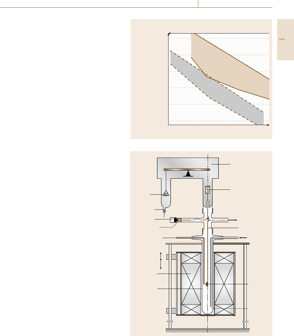
according to these systematic cases. For further illustra-
tion in Fig. 12.49 examples of values of the parabolic
rate constant are given for protective oxides scales and
a temperature range 800–1400
◦
C [12.102]. This fig-
ure shows that alumina surface scales are superior to
chromia surface scales with regard to the protective ef-
fect. Figure 12.49 furthermore can serve for orientation
Part D 12.8
Corrosion 12.8 High-Temperature Corrosion 723
Fig. 12.49 Oxidation rate constants k
p
for the alloy
groups Al
2
O
3
-scale formers and Cr
2
O
3
-scale formers (af-
ter [12.102])
whether the measured values determined in the experi-
ments characterize protective or nonprotective behavior
of the materials.
Thermogravimetric Testing. Mostly in scientific labo-
ratories the thermogravimetric method is a widely used
type of test to investigate the oxidation kinetics and
other types of high-temperature corrosion continuously
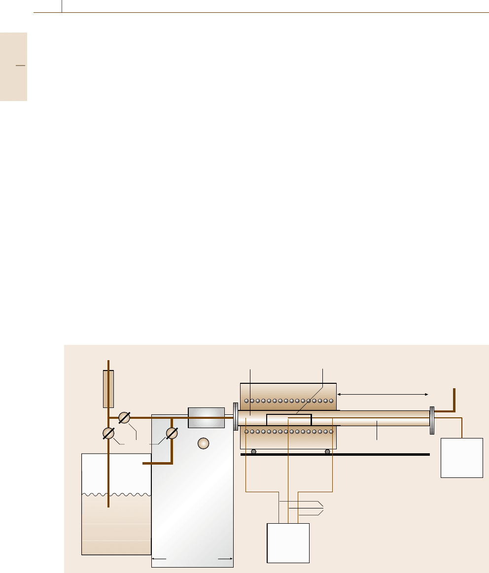
in situ. The principles of the equipment are given in
Fig. 12.50. The weight of the specimen is continuously
recorded by a laboratory balance, which usually sits
on top of a laboratory furnace. To hang the specimen
platinum wires or silica strings, which are supposed
to be inert in most environments, are normally used.
(It should however be mentioned here that under cer-
tain conditions even platinum and silica may evaporate
and, thus, lead to a decrease in weight of the string
which is also measured by the balance.) The speci-
men and the weighing system are usually encapsulated
in a retort to allow the use of defined gas composi-
tions. The interior of the laboratory balance should be
shielded against penetration of the reactive gas in the
furnace by counterflow of inert gas (e.g. Ar). The gas
entrance should be opposite to the gas exit. In most
cases the retort is manufactured from quartz. Espe-
cially at very high temperatures, alumina retorts are
also used. For accelerated testing the measurements
are sometimes performed under thermal cycling con-
ditions (see later). The same equipment can be used
with a moveable furnace, the movement of which is
controlled by an electronic device that allows defined
temperature cycles. The temperature at the specimen
is monitored by a thermocouple, which is placed close
to the specimen, although no friction between the ther-
mocouple and the specimen should occur. Furthermore
any friction between the quartz string or the platinum
wire leading to the balance and the retort or tube walls
should be avoided. Further recommendations for the
thermogravimetric tests are given below in the section
on continuous and discontinuous isothermal exposure
testing.
As indicated in Fig. 12.50 it is also possible to
combine this type of measurement, especially in the
case of thermal cycling testing, with acoustic emission
measurements. In this case the platinum wire that is
connected to the specimen can be used simultaneously
as an acoustic waveguide. Acoustic emission signals
Temperature (°C)
Parabolic
rate constant
(g
2
/cm
4
s)
10
–9
10
–10
10
–11
10
–12
10
–13
10
–14
1300 800
10
4
/T (K
–1
)
8
“Cr
2
O
3
”-
alloys
“Al
2
O
3
”-
alloys
796
900100011001200
Temperature
controlled
microbalance
Counter
weight
Ar-counter
stream
AE-sensor
Polymer seal
Thermocouple
Furnace
(moveable)
Quartz tube
Acoustic decoupler
(PTFE)
Gas exit
Pt-wire and
waveguide
Testing gas
Specimen
Gas inlet
Fig. 12.50 Schematic of a thermobalance for continuous in situ
mass measurements
Part D 12.8
724 Part D Materials Performance Testing
can reveal the extent to which cracking or spalling of
the oxide scale occurs either during isothermal or during
cyclic oxidation. The results of the thermogravimet-
ric measurements are the curves shown schematically
in Fig. 12.48. However, a major disadvantage of this
method is that only one sample can be tested at a time so
that generating a large number of comparative data for
different materials is a lengthy process. This is the main
reason why industrial laboratories prefer to test multiple
samples simultaneously. This issue will be addressed in
the next section.
Continuous and Discontinuous Isothermal
Exposure Testing
To accommodate a larger number of specimens in one
furnace a special arrangement of equipment is neces-
sary, as shown schematically in Fig. 12.51. This equip-
ment is again composed of a temperature-regulating
device for heating the test piece(s) uniformly at a con-
stant temperature and, ideally, a testing portion capable
of separating the test piece(s) from the outside air (i. e.,
a closed system). Since for many materials humidity in
the test environment may have a significant effect on
oxidation behavior, a humidifying regulator should be
used to continuously supply a gas kept at a constant
humidity, which should be monitored with a hygrom-
eter. As for all closed systems, including those for
thermogravimetric testing, the gas supply should be
Gas supply
Va lve s
Heated device
containing catalyst
for non equilibrium
gas mixtures
(Hygrometer)
Humidifying
regulator:
Hot water or
electronic type
Heater
Test piece chamber Test piece supporter
Gas exhaust
Direction of
furnace movement
Measuring
instrument
for thermal cycling
Thermocouple
Thermocouples
Temperature
regulating
device
Heating device
Heating zone with
ribbon heater
Power
control
device
Gas flow
meter
Fig. 12.51 Basic design of a horizontal exposure furnace for discontinuous oxidation/corrosion testing
controlled by a gas-flow meter. It is important that the
test-piece chamber is not composed of a material that
reacts with the test environment during the test to a de-
gree that changes the composition of the atmosphere.
If closed systems with a test-piece chamber cannot be
used, then tests may also be performed in an open sys-
tem with laboratory air. In this case it is recommended
that the humidity of the air should be recorded and
that the laboratory should be kept free from tempera-
ture changes and the influence of weather conditions as
far as possible.
The furnace has to be characterized prior to test-
ing to determine the length of the isothermal zone
inside the furnace and the set point of the apparatus.
A common method is by the use of an independent
movable thermocouple. The draft of the present ISO
work item recommends that the temperature-regulating
device should be capable of guaranteeing that the tem-
perature of the test piece is kept within a permissible
range, given in Table 12.5. The material of the ther-
mocouples has to withstand this test temperature. The
temperature has to be measured by a suitable device
according to ASTM E 633-00 [12.103]. Thermocou-
ples of type S (Pt-10% Rh/Pt), type R (Pt-Pt/13% Rh)
up to 1000
◦
C or type B (Pt/30% Rh-Pt/6% Rh) up to
1700
◦
C are preferred. A thermocouple should be po-
sitioned close to the test-piece surface and must be
calibrated in accordance with standards ASTM E 220-
Part D 12.8

Corrosion 12.8 High-Temperature Corrosion 725
Table 12.5 Permissible tolerance of temperature of test piece [12.97]
T ≤ 573 K 573 K < T ≤873 K 873 K < T ≤1073 K 1073 K < T ≤ 1273 K T > 1273 K
±2K ±3K ±4K ±5K ±7K
02, ASTM E 230-02 and ASTM E 1350-97 [12.104–
106]. If, however, the environment does not allow
the use of such thermocouples in this way the test-
piece temperature has to be deduced from the furnace
calibration using dummy test pieces and appropriate
thermometry in an inert environment. The thermo-
couple should be capable of confirming that the test
temperature is within the range given in Table 12.5.It
should be located at a defined, fixed position as close to
the test pieces as possible.
When a humidifying regulator is used it should be
capable of adjusting to the desired humidity and the
space between the humidifying regulator and the test-
piece chamber should be kept above the dew point to
avoid condensation. The water-vapor content should be
measured, which can be achieved by, e.g., the use of
a hygrometer before the test-piece chamber or mea-
suring the amount of water after condensation of the
exhaust gases. The gas flow has to be high enough to
ensure that no depletion of the reacting species will oc-
cur. At the same time the gas flow must be slow enough
to allow the gas mixture to preheat and in some appli-
cations to reach reaction equilibrium. The TESTCORR
document recommends 1–10 mm/s.
It is recommended that the test pieces have a mini-
mum surface area of 500 mm
2
[12.92]. Their shape can
be a rectangular plate, a disc or a cylinder. Final surface
finishing of the test pieces should be 1200 grit according
to the Federation of European Producers of Abra-
sives (FEPA) standard 43-1984 R 1993 [12.107]and
ISO 6344 [12.108]. Deformation by marking, stamping
or notching of the surface should be avoided. Identifi-
cation of the test pieces should be solely on the basis of
recording their relative position within the test chamber.
In particular for hanging specimens, e.g. for the ther-
mogravimetric test, holes for the test-piece support are
permissible. The test pieces must be dried after degreas-
ing in an ultrasonic bath using isopropanol or ethanol.
Before exposure the mass of the test pieces m
T
(t
0
)has
to be determined by three independent measurements
with the difference between the measurements not ex-
ceeding 0.05 mg.
Several test pieces exposed for different times are
necessary to define the oxidation kinetics of the ma-
terial. Therefore it is recommended that duplicate test
pieces are used with (at least four) exposure times in-
creasing progressively (e.g., 10 h, 30 h, 100 h, 300 h,
...). The material used for the test-piece supports
should not react at the test temperature neither with the
environment nor with the specimen. Examples of rec-
ommended test-piece supports are shown in Fig. 12.52.
Where the possibility of depletion of active species in
the test atmosphere is a concern, the exchange of the
test atmosphere can be improved by the use of holes
or slots in the bottom part of the side walls of the
test-piece support. To remove volatile compounds it is
furthermore recommended that new test-piece supports
should be baked for at least 4 h at 1000
◦
Cinair.In
addition to the mass of the test pieces, that of the test-
piece supports m
s
(t
0
) should be determined prior to
exposure.
Thermal Cycling Oxidation Testing
In the majority of industrial applications temperatures
are never constant. Therefore temperature cycling oxi-
dation/corrosion tests are most often used in industry.
The test equipment is rather similar to that for isother-
mal testing, with the major difference that either the
specimen or the furnace can be moved so that tem-
perature cycles are possible in the test. In Figs. 12.50
and 12.51 the test equipment shown for isothermal test-
ing already allowed for the possibility of moving the
furnace, so that in the same equipment cyclic oxida-
tion testing would also be possible. The advantage of
the equipment shown in Figs. 12.50 and 12.51 is that
these tests can be performed in a defined environment.
In some of the more traditional thermal cycling oxida-
tion test rigs the specimens are moved by some device
out of and into the furnace, which usually requires
that these tests are performed in an open system. As
mentioned above, closed systems with defined environ-
ments are preferred over open systems with laboratory
air.
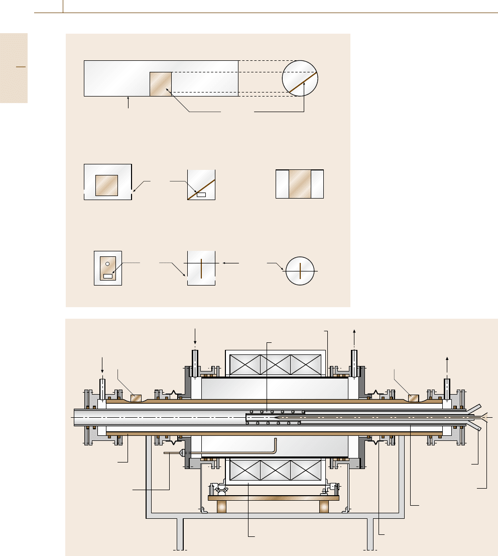
For completeness it should be mentioned that, as
well as tests with small laboratory specimens, compo-
nent tests, e.g. with complete heat-exchanger tubes, can
even be performed under thermal cycling conditions, as
shown by the schematic in Fig. 12.53. In this case the
furnace consists of two half shells that can be moved
apart on a rail system so that the test-piece chamber is
at ambient temperature when the furnace is open. The
test piece, which in this example is a heat-exchanger
Part D 12.8
726 Part D Materials Performance Testing
Side view
a)
b)
c)
Test piece
High purity alumina tube for
supporting test piece
Test piece support and basic layout of test piece arrangement – tube design
Test piece support and basic layout of test piece arrangement – U-shaped design
Test piece support and basic layout of test piece arrangement – rod supported design
Holes
Holes Alumina
rod
Cross sectional
view
Side view
Side view
Cross sectional
view
Cross sectional
view
Top view
Top view
Fig. 12.52 (a) Test-piece support and
basic layout of test-piece arrangement
– tube design; (b) Test-piece sup-
port and basic layout of test-piece
arrangement – U-shaped design;
(c) Test-piece support and basic
layout of test-piece arrangement –
rod-supported design
Ar
A
Testing gas Testing gasQuartz tube
Inner heater
Current lead
Ceramic tube
Plastic bellows
Mobile half furnace
Controlling
thermocouple
Test tube
Measuring
thermocouple
AE sensor
Ar
B
AE sensor
Fig. 12.53 Equipment for thermal cyclic testing of heat-exchanger tubes (after [12.109])
Part D 12.8
Corrosion 12.8 High-Temperature Corrosion 727
tube, is placed inside a quartz tube and sealed at the
ends with flanges. This design allows the possibility of
having defined environments on the outer surface of the
tube as well as on the inner surface. These two envi-
ronments can even be different from each other, e.g.
combustion gas on the outside and steam on the in-
side of the tube. Component tests as in this example
are always desirable when geometrical effects of these
components on the oxidation behavior are to be inves-
tigated. Figure 12.53 again includes the possibility of
using the acoustic emission technique for the detection
of failure of the protective oxide scales due to thermal
cycling and spalling.
Generally all the recommendations given in the con-
tinuous and discontinuous isothermal exposure testing
section are also applicable to thermal cycling testing.
The difference compared to discontinuous isothermal
testing is that in thermal cycling testing the temper-
ature cycles always have the same shapes. Based on
a detailed scientific model calculation the parameters
characterizing such a thermal cycle have been deter-
mined as follows [12.110, 111]. The heating period of
the cycle starts when the test piece enters the furnace
and ends with the beginning of the hot dwell time. The
latter is defined as the time when the actual tempera-
ture exceeds 97% of the desired hot dwell temperature
measured in kelvin. The hot dwell time ends and the
cooling time starts when the heating of the test piece is
stopped, e.g. by the removal of the test piece from the
furnace. The end of the cooling time is defined as when
the actual test-piece temperature falls below 50
◦
C. The
cold dwell time starts after the test pieces have cooled
below 50
◦
C and ends when the test pieces are heated
again. The characteristic parameters of a thermal cycle
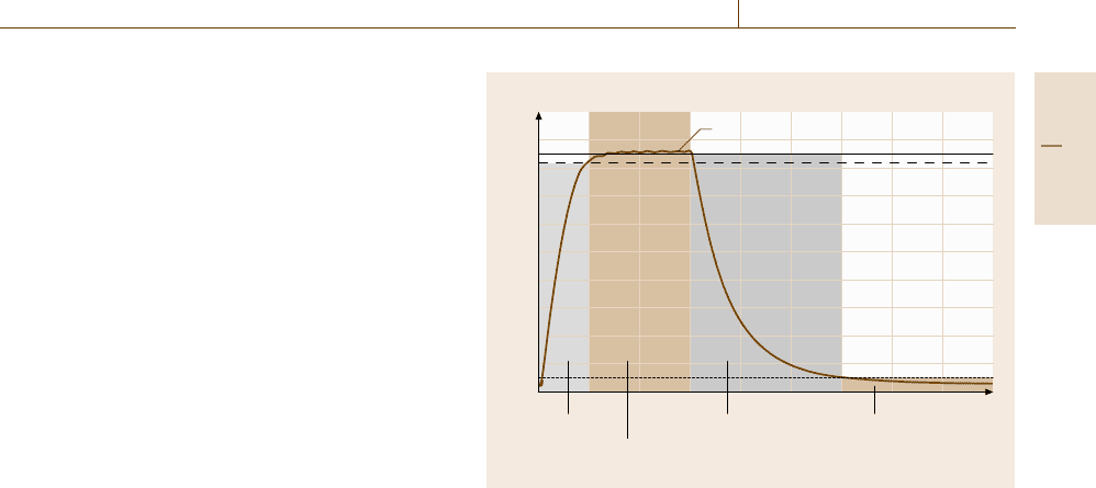
are summarized in Fig. 12.54.
Depending on the type of industrial application,
three general types of thermal cycles are regarded as
typical. The first type is long-dwell-time testing, which
aims to simulate conditions in large-scale industrial
facilities encountered in applications such as power-
generation plants, waste-incineration plants or chemical
industry. In these applications the metallic components
are designed for extremely long-term operation, e.g.
typically for up to 100 000 h. Thermal cycling of the
materials occurs due to plant shutdowns, e.g. for reg-
ular maintenance, or due to unplanned shutdowns as
a result of offset conditions. Therefore, the time inter-
vals between various thermal cycles are relatively long
and the number of cycles is (related to the long op-
eration time of the components) relatively small, e.g.
typically around 50 cycles. A recommended test cycle
T (°C)
T
dwell
Hot dwell
(T >0.97 T
dwell
)
Cold dwell
(T <50 °C)
Heating time Cooling time t (min)
900
800
700
600
500
400
300
200
100
1000
0
0908070605040302010
Fig. 12.54 Schematic of a temperature cycle in thermal cycling ox-
idation testing
for this application consists of an overall time of 24 h
with a 20 h hot dwell time and 4 h period, which in-
cludes the cooling time, the cold dwell time and the
heating time.
The second type is thermal cycling with short
dwell times, which is typically experienced in ap-
plications such as jet engines, automotive parts, and
heat-treatment facilities. The intervals between start and
shutdown of the facilities are generally much shorter
than in applications with long dwell times. Also the life
times and/or the times until complete overhaul/repair
(typically 3000–30 000 h) are shorter and, depending
on the specific practical application, the number of
cycles is much higher than in the cases above. The rec-
ommended testing cycle in this case consists of one hour
hot dwell time and 15 min cold dwell time.
The third type of testing has ultrashort dwell times
and mainly addresses applications of high-temperature
alloys as heating elements in the form of wires or foils.
Another typical application in which such ultrashort
cycles prevail is catalyst foil carriers, e.g. in cars. In
such applications the number of cycles is related to the
overall design life (typically several hundred to a few
thousand hours) and can be extremely high, and the
time intervals between heating and cooling can be as
low as minutes or even seconds. Such conditions are
commonly also encountered in a number of other in-
dustrial applications such as burners and hot gas filters,
as well as in a large variety of domestic applications
where metallic heating elements are used e.g. in cook-
ing plates, toasters, boilers, dryers, and fryers. The
Part D 12.8