Canale L.C.F., Mesquita R.A., Totten G.E. Failure Analysis of Heat Treated Steel Components
Подождите немного. Документ загружается.

full use of compressive residual stresses in dyna-
mically loaded parts can be made in this way.
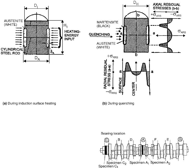
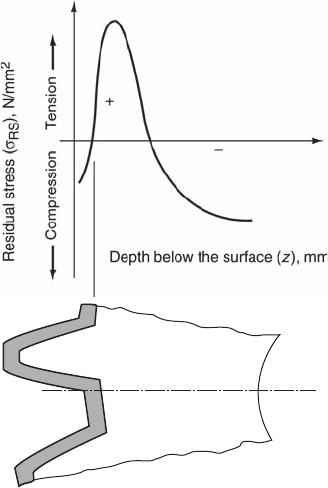
Figure 52 shows a cylindrical workpiece or
sample with initial diameter D
I
and initial height
H
I
. Its purpose is to show the process of residual
stresses after induction surface treating in the
central part of the workpiece (Ref 15, 27). With
energy input to the thin surface layer, the initial
diameter increases to the value of D
A
. Change of
diameter is associated with thermal expansion of
the material and is due to ferrite and/or pearlite
transformed into austenite.
After quenching, a thin surface layer with a
martensite microstructure is obtained that has a
different specific volume than the initial micro-
structure. The hardened surface layer is ready to
receive a greater diameter (D
H
), which is resis-
ted by the initial microstructure. Of interest are
the residual stresses in the radial and axial
directions. Residual stresses are compressive in
the hardened layer, then they change into tensile.
Residual stresses in the axial direction are
compressive in the middle part of the hardened
layer and turn into tensile below the hardened
layer. In this way, very high tensile residual
stresses are achieved at the bottom of the
hardened layer. Compressive residual stresses
prevail in the remaining part of the nonhardened
surface layer. A residual-stress profile is un-
favorable in the transition zone between the
hardened layer and the rest of the nonhardened
part of the workpiece.
The transition from tensile to compressive
residual stresses presents a serious danger for
catastrophic failure. From the aforementioned
it can be understood that the workpiece must
be slowly heated and also quenched with the
correct cooling rate. The actual cooling rate is
very important throughout the martensitic trans-
formation and must be as close as possible to the
critical cooling rate. The quenching process
must be carried out very carefully in the mar-
tensitic transformation temperature range to
ensure internal stresses lower than the yield
point.
Figure 53 presents a crankshaft formed by hot
forging, and Fig. 54 shows the manufacturing
procedure from blank to crankshaft (Ref 15, 36).
The procedure of forming should be carefully
prescribed, including the initial and final tem-
peratures of forging and the uniform plastic
deformation rate for the entire volume.
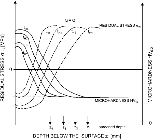
Fig. 51 Microhardness and residual-s tress profiles at various heating times, t
H1
–t
H4
. Source: Ref 15, 54
458 / Failure Analysis of Heat Treated Steel Components
Name ///sr-nova/Dclabs_wip/Failure_Analysis/5113_417-501.pdf/Chap_13/ 18/8/2008 4:01PM Plate # 0 pg 458
This will ensure a fine-grained, banded
microstructure contributing to a favorable rela-
tionship between strength and toughness of the
product. The forging procedure is followed by
annealing to remove the residual stresses in-
curred by the refinement procedure applied to
forgings. Deformation of the crankshaft occurs
after heat treatment, as early as in the phase of
heating to the austenitization temperature. Due
to stress relief as well as the effects of nonuni-
form cooling of the product, it is necessary for
the forgings to be subjected to straightening
prior to mechanical treatment. If necessary ad-
ditional annealing can be prescribed to remove
internal stresses induced by straightening. This
is followed by turning and rough grinding to
approach the final dimensions of the product.
The technology of manufacturing the crankshaft
involves careful selection of the conditions of
turning and subsequent rough grinding to avoid
the occurrence of internal stresses that would
remain in the material even after induction sur-
face hardening and grinding, thus reducing the
fatigue strength of the material. Induction hard-
ening may be preceded by stress annealing if the
depth of the surface hardening is smaller than the
depth of the damaged layer, since, in this way, it
is possible to change the unfavorable stress state
in the surface layer induced by machining. In
this case, the depth of the induction surface
hardening was greater than the depth of the
damaged surface layer; therefore, machining
could immediately be followed by induction
surface hardening. After induction surface
hardening, the size and distribution of residual
stresses contribute to toughness and fatigue
strength of the material. In these tests, induction
surface hardening was followed by finish grind-
ing and nondestructive magnetic inspection of
the surface to reveal the possible existence
of cracks on the product surface.
Crankshafts were taken from production after
induction surface hardening with the heat treat-
ment and machining conditions as specified in
the technology sheet. The residual stresses on
the main crankshaft bearings were measured on
the bearing location in the middle (sample A in
Fig. 53), on the extreme left side (sample C) and
on the extreme right side (sample G).
Fig. 52
Radial and axial residual-stress profiles after induction hardening the surface layer in the central part of a cylinder steel rod.
Source: Ref 15, 27
Fig. 53
Schematic presentation of a crankshaft with marked
main bearing locations. Source: Ref 15, 36
Induction Hardening / 459
Name ///sr-nova/Dclabs_wip/Failure_Analysis/5113_417-501.pdf/Chap_13/ 18/8/2008 4:01PM Plate # 0 pg 459
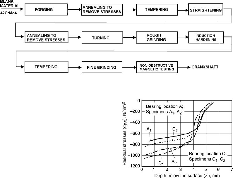
Figure 55 shows residual-stress distribution
after induction surface hardening in the central
bearing location (sample A) and on the extreme
left side (sample C) (Ref 15, 20, 44). For both
locations, residual stresses were measured on
two samples. The distribution of residual stres-
ses on location A is very similar on both sam-
ples, as expected, with the highest compressive
stress ranging between 1020 and 1060 N/mm
2
at
a depth of approximately 250 mm and then
slowly dropping to a depth of 3.5 mm.
The residual-stress distribution after induc-
tion surface hardening on bearing location C is
very similar to that in the central bearing loca-
tion A, except that its absolute values are slightly
lower, and a distinct decrease in the residual
stresses can be noted as early as a depth of ap-
proximately 3 mm, reaching its minimum value
at a depth of approximately 5.0 mm.
The residual-stress distribution is just as
favorable as in the central location, except that
its absolute values are slightly lower. The dif-
ference in the residual-stress distribution can
be related to the period of overheating in the
austenitization temperature, which resulted in a
thinner layer in austenitization and also a thinner
hardened surface layer.
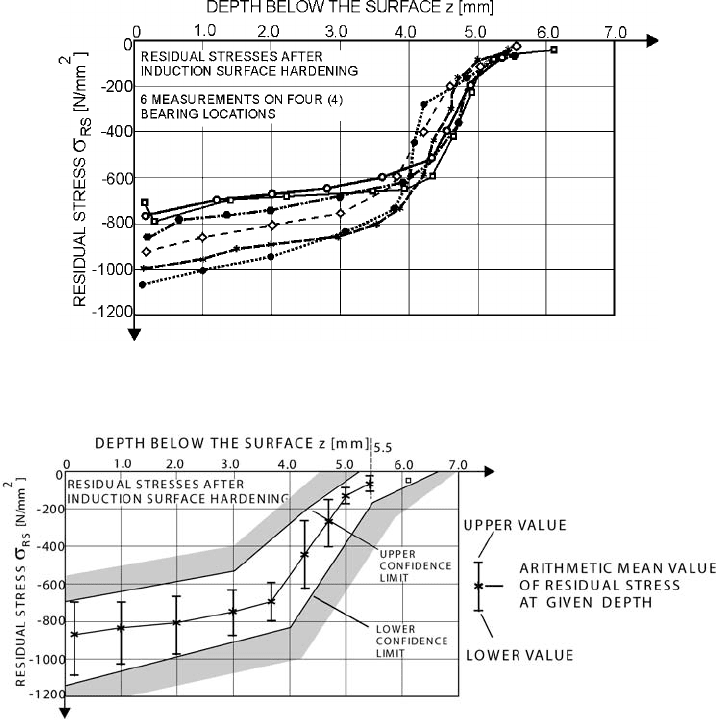
Figure 56 shows a zone of the measured
values of residual stresses at four bearing loca-
tions of the knee shaft (Ref 54). The arithmetic
mean value for characteristic depths of the har-
dened layer was determined, and the highest and
lowest values of residual stresses at the given
depth were established, respectively.
The upper and lower values of the residual
stress with the individual depths of the hardened
layer were defined by the range of scatter of
residual-stress values. The upper and lower con-
fidence limits were defined using a statistical
data analysis of the measured values of the resi-
dual stresses through the hardened-layer depth.
Figure 57 shows a zone of the scattered values
of residual stresses, the calculated variation of
mean values in the individual depths, and the
zone determined by the upper and lower
confidence limits for the hardened-layer depth,
to a depth of 5.5 mm (Ref 54).
The zone between the upper and lower con-
fidence limits is important and requires a very
definite gradient of residual stresses. Where the
limit, that is, the depth, should be set and where
the gradient should be controlled depends on the
chosen induction-heating conditions. The heat-
ing conditions applied in the study indicated that
the specified gradient of residual stresses should
be ensured at a depth ranging between 3.0 and
5.0 mm.
A practical application showed that the stress
gradient between the surface and a depth of
Fig. 54 Machining and heat treatment procedure from blank to crankshaft. Source: Ref 15, 36
Fig. 55
Residual-stress profile after induction surface hard-
ening on sample A of the mean bearing location in
the middle of the crankshaft and on sample C on the extreme left
side. Source: Ref 15, 20, 44
460 / Failure Analysis of Heat Treated Steel Components
Name ///sr-nova/Dclabs_wip/Failure_Analysis/5113_417-501.pdf/Chap_13/ 18/8/2008 4:02PM Plate # 0 pg 460
3.0 mm was not problematic, since the values
obtained lay in this range in all cases. Difficul-
ties may be encountered in induction heating
and induction hardening, respectively, if the
residual-stress value obtained at the surface lies
at the lower limit of the scattered results. This
means that the measured compressive residual
stresses are at the lower limit as well, which
may result in a steeper gradient to the depth of
3.0 mm. Consequently, the required residual-
stress variation cannot be achieved through the
entire hardened layer.
The cylindrical specimen was surface induc-
tion heated to a temperature of 980
C and
then quenched in saltwater. Figure 58 shows
the calculated distribution of individual
microstructural phases from the surface to the
center of the cylindrical specimen at the end of
cooling (Ref 20, 47).
The initial microstructure was preserved to a
radius, r, of 5.5 mm. In the radii between 5.5 and
6.6 mm, the pearlitic-ferritic microstructure and
low-carbon martensite appeared. With the radii
exceeding 6.6 mm, a fine martensitic micro-
structure with approximately 6.0% residual
austenite was obtained due to intensive cooling.
With the selected conditions of induction heat-
ing and fast cooling of the specimen, no homo-
geneous martensite was formed in the surface-
hardened layer. Figure 59 shows the calculated
and measured variations of individual com-
ponents of residual stresses (Ref 20, 47). The
Fig. 56 Residual-stress profiles for six measurements on four bearing locations after induction hardening. Source: Ref 54
Fig. 57
Determination of upper and lower confidence limit and arithmetic mean values of residual stresses through the hardened
depth. Source: Ref 54
Induction Hardening / 461
Name ///sr-nova/Dclabs_wip/Failure_Analysis/5113_417-501.pdf/Chap_13/ 18/8/2008 4:02PM Plate # 0 pg 461
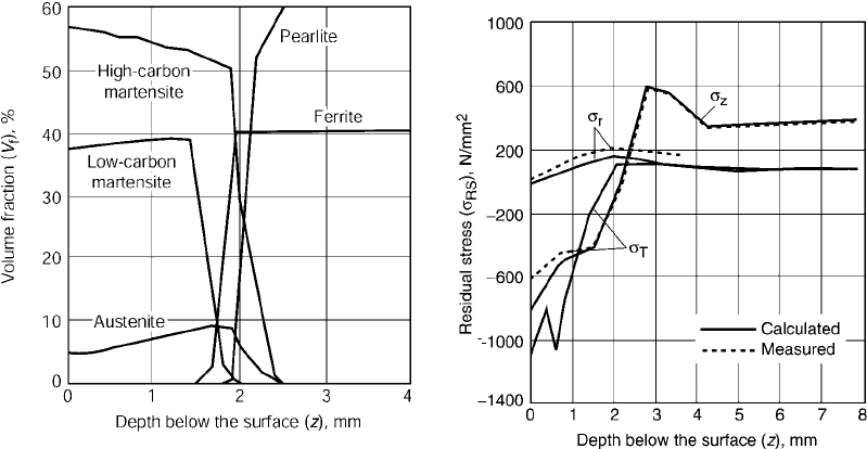
calculated variations of residual stresses repre-
sent high compressive stresses at the surface,
that is, the axial component of residual stresses,
s
z
, equals 803 N/mm
2
, and the tangential one,
s
T
,is588 N/mm
2
. On the contrary, the tensile
residual stresses were calculated after hardening
in the core, with the preserved pearlitic-ferritic
microstructure. Thus, the axial component of
residual, stresses, s
z
, calculated for the core
equalled to +370 N/mm
2
and the tangential
one, s
T
, was +62 N/mm
2
. The diagram in
Fig. 59 indicates that the maximum tensile
stresses were attained in the transition zone
between the hardened layer and the unhardened
one (Ref 47). At a greater depth, very low stress
gradients occurred, and in the opposite direction,
that is, in the thin surface layer to a depth of
2.5 mm, very high gradients of residual stresses
occurred. The variations of residual stresses
were determined experimentally by the x-ray
diffraction method. The large gradient changes
of the measured residual stresses in the
thin surface layer can also be confirmed by
measurement. The results of the measured and
calculated variation of residual stresses in the
surface-hardened layer sufficiently agree with
small local deviations. To determine the local
deviations of the variation and of residual
stresses, numerous calculations were made with
varying physical parameters of the material as
well as different process parameters.
A particular problem with steels having
ferritic-pearlitic and pearlitic-ferritic micro-
structures, respectively, is that heating of short
duration does not ensure complete homo-
genization of austenite.
Figure 60 shows the influence of inhomo-
geneity of austenite on the level of residual
stresses, which is particularly noticeable in the
martensite zone (Ref 20, 47). The initial inho-
mogeneous austenitic microstructure resulted
in the appearance of a martensitic transfor-
mation with a small fraction of residual auste-
nite. With regard to the volume fraction of
martensite and residual austenite, plastification
of the material occurred, which produced in-
ternal stresses and the variation of residual
stresses, particularly in the thin surface-
hardened layer.
Figure 61 shows the calculated distribution of
residual stresses due to heating of the specimen
with heating rates of 200 and 800
C/s to a
temperature of 1050
C, followed by cooling
with a cooling rate of 1500
C/s (Ref 20, 47).
With the high heating rate, 800
C/s, a very steep
transition of residual stresses from the com-
pressive to the tensile zone was obtained, which
resulted in a decrease in fatigue strength. With
the considerably lower heating rate, 200
C/s,
the variation of residual stresses in the thin
surface layer was essentially more favorable than
that with the high heating rate. The variation of
Fig. 58
Calculated distribution of microstructures along
the cylinder radius at the end of cooling. Source:
Ref 20, 47
Fig. 59
Calculated and measured residual-stress profiles
after induction surface hardening. Source: Ref 20, 47
462 / Failure Analysis of Heat Treated Steel Components
Name ///sr-nova/Dclabs_wip/Failure_Analysis/5113_417-501.pdf/Chap_13/ 18/8/2008 4:02PM Plate # 0 pg 462
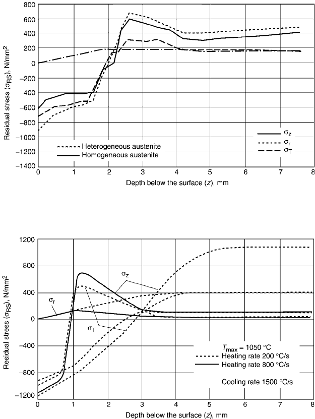
the tangential and axial components of residual
stresses permits the following observations:
With the lower heating rate, the residual
stresses at the surface are lower by 100 to
200 N/mm
2
.
The stress gradient for the tangential and
axial components, s
t
and s
z
, is very small in
the subsurface, from a depth of 0.7 to
4.5 mm.
The transition from compressive to tensile
residual stresses does not occur before a
depth of 2.6 mm due to a small stress
gradient.
The radial component of residual stresses is
0 at the surface. In the subsurface, it is of the
tensile character. Thus, it equals approximately
50 N/mm
2
with the higher heating rate, 800
C/
s, and is 400 N/mm
2
with the lower rate,
200
C/s.
Figure 62 shows simulation of the variation of
residual stresses with a favorable rate of surface
induction heating, 200
C/s, which gives the
Fig. 60
Residual-stress profiles after induction surface hardening for heterogeneous and homogeneous austenite at austenitizing
temperature. Source: Ref 20, 47
Fig. 61
Simulated residual-stress profiles at maximum surface temperature (T
max
= 1050
C) with various heating rates
(V
H1
= 200
C/s and V
H2
= 800
C/s) and at a given cooling rate, V
C
, of 1500
C/s. Source: Ref 20, 47
Induction Hardening / 463
Name ///sr-nova/Dclabs_wip/Failure_Analysis/5113_417-501.pdf/Chap_13/ 18/8/2008 4:02PM Plate # 0 pg 463
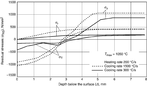
maximum temperature obtained at the surface,
that is, 1050
C (Ref 20, 47). This was followed
by quenching with two cooling rates, 1500 and
300
C/s.
The variation of the tangential and axial
components of residual stresses permits the
following observations:
With the higher cooling rate, compressive
residual stresses are obtained at the surface,
that is, the axial component of 800 N/mm
2
and the tangential component of 1050
N/mm
2
.
With a low gradient, the axial and tangential
components of the stresses vary; they change
their sign to the tensile zone only at a depth
between 2.6 and 2.8 mm.
With the lower cooling rate, considerably
lower compressive residual stresses are
obtained at the surface, that is, an axial
component of 275 N/mm
2
and a tangen-
tial component of 390 N/mm
2
.
A comparison of the axial and tangential
components of residual stresses indicates
that because of the considerably reduced
cooling rate, the latter is lower in the thin
surface layer by a factor of 3.
The gradients of residual stresses with a
higher or lower cooling rate are favorable,
since a slow decrease of compressive to
tensile residual stresses results in a minor
susceptibility of a machine part to fatigue
under dynamic loads.
Residual stresses due to surface induction
hardening of the gear wheels were calculated
along the tooth surface during the heating pro-
cess as well the quenching process.
The series of images in Fig. 63(a) show dis-
tributions of internal stresses during the heating
process after 20, 60, 100, and 187 s (Ref 52).
The profile variation of internal stresses indi-
cates that:
In the initial heating phase, the internal
stresses in the tooth root are of the com-
pressive character and reach up to 700 N/
mm
2
; with further heating, they change into
tensile internal stresses ranging from +200
to +300 N/mm
2
.
They are considerably lower in the zone
reaching from the root to the pitch circle.
Up to a heating time of 60 s, they are of
the tensile character and reach up to 700
N/mm
2
. With further heating, they gradually
change to compressive stresses attaining
100 N/mm
2
.
They are obviously very low and insigni-
ficant in the upper part of the gear-wheel
tooth, from the pitch-circle diameter to the
tip of the tooth, therefore, they are not plot-
ted. For this reason, deformations are the
greatest at the tip of the gear-wheel tooth.
The series of images in Fig. 63 show changes
of internal stresses during the heating pro-
cess (Fig. 63a) and the cooling or quenching
Fig. 62
Simulated residual-stress profiles at maximum surface temperature (T
max
= 1050
C) with heating rate, V
H
, of 200
C/s and at
a various cooling rates (V
C1
= 1500
C/s and V
C2
= 300
C/s). Source: Ref 20, 47
464 / Failure Analysis of Heat Treated Steel Components
Name ///sr-nova/Dclabs_wip/Failure_Analysis/5113_417-501.pdf/Chap_13/ 18/8/2008 4:02PM Plate # 0 pg 464
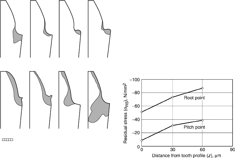
process (Fig. 63b) (Ref 20, 52). It is charac-
teristic of the quenching process that con-
siderably higher internal stresses occur and are
more important in the tooth root. The figures
show the magnitude and variation of internal
stresses after the cooling times of 0.1, 1, 10, and
300 s, when the gear wheel is finally cool. The
series of graphic representations of the internal
stresses at the tooth surface indicate that:
In the initial quenching phase, at 0.1 and 1 s,
the internal stresses are of the tensile char-
acter along the entire tooth height. They are
the highest in the tooth root and gradually
decrease toward the tip of the tooth.
Between the quenching times of 1 and 10 s,
the sign of the internal stresses changes,
becoming gradually of the compressive
character and ranging between 100 and
150 N/mm
2
in the upper part of the tooth and
up to 600 N/mm
2
in the tooth root.
At the end of quenching, after the cooling
time of 300 s, the internal stresses change
considerably only in the tooth root and at-
tain up to 1500 N/mm
2
.
The magnitude of residual stresses was also
measured with the x-ray diffraction method and
strain gages. Figure 64 shows the results of stress
measurements in the pitch circle, that is, at the
middle of the tooth surface for both teeth and in
the tooth root where critical residual stresses
occur (Ref 20, 52). By means of the x-ray dif-
fraction method, it was found that:
The highest residual stresses occur in the
root. At the surface they equal approximately
540 N/mm
2
, then increase to 750 N/
mm
2
at a depth of 30 mm to reach 870 N/
mm
2
at a depth of 60 mm.
The residual stresses are a bit lower in the
middle of the tooth surface, that is, at the
pitch circle. At the surface, they equal ap-
proximately 90 N/mm
2
, then gradually in-
crease with a greater depth to reach 400 N/
mm
2
at a depth of 60 mm.
A general conclusion can be drawn that the
experimental as well as theoretical results agree
very well and provide useful information,
especially to a technologist in the manufacture
of gear wheels.
Figure 65 shows a part of a gear in cross
section, with residual stress distribution in the
surface-hardened layer of the gear tooth (Ref 15,
20). Also in this case, a residual-stress distri-
bution typical of induction hardening is ob-
tained, that is, compressive residual stresses in
the hardened layer with a martensite micro-
structure, followed by tensile residual stresses,
and, at greater depth, compressive residual
stresses once again. The size and distribution of
residual stresses can be influenced by power
density.
(b)
(a)
050
Stress σ
0.1 s 1 s 10 s 300 s
20 s 60 s 100 s 187 s
daN/mm
2
Fig. 63
Principal stress during (a) induction surface
heating process and (b) quenching process. Source:
Ref 20, 52
Fig. 64
Residual-stress measurements on the root below the
tooth surface. Source: Ref 20, 52
Induction Hardening / 465
Name ///sr-nova/Dclabs_wip/Failure_Analysis/5113_417-501.pdf/Chap_13/ 18/8/2008 4:02PM Plate # 0 pg 465
A number of authors have done research into
the effects of power density or energy input used
in heating, with the purpose of determining op-
timal induction-hardening conditions that lead
to good mechanical properties of gears. Lower
power density at the same current frequency
requires longer heating times at the same depth
of the hardened layer and results in higher com-
pressive residual stresses with a moderate tran-
sition of residual stresses from the compressive
into the tensile region.
In induction hardening of gears, it is necessary
to ensure the most uniform depth of the hardened
layer to achieve a symmetric distribution of
residual stresses in the gear tooth cross section.
Workpiece Distortion in Induction
Surface Hardening
Dimensional changes of the workpiece are
closely related to the internal stresses occurring
in heating and cooling. During heat treatment,
when internal stresses in the workpiece are
higher than the yield point, distortion of the
workpiece takes place. When the workpiece has
an axisymmetric shape, it is very important to
place the induction coil so that symmetric
heating and quenching is achieved, resulting in
uniform thickness of the hardened layer with a
martensitic microstructure.
Figure 66 shows induction surface hardening
of a cylindrical rod and tube. When the gap
between the coil and the workpiece varied from
the maximum gap, r
1
, to the minimum gap, r
2
,
that is, r
1
4r
2
, the hardened layer thickness
varied also (Ref 15, 27). This means that the side
of the workpiece with a thicker hardened layer
will suffer greater changes in volume than the
side with the thin layer. A changing thickness of
the hardened layer will result in distortion or
curvature of the cylindrical rod in the direction
of the thinner induction-hardened layer.
Figure 66(a) shows a cylindrical tube with an
induction-hardened inner surface. Asymme-
trical placement of the coil inside the tube (hole,
bore) causes differences in the gap between the
coil and the bore surface inside the workpiece.
The conditions of heating are very similar to
those mentioned earlier, and the cylindrical rod
bends in the direction of the thicker hardened
layer.
Similar distortion happens on prismatic bod-
ies where the specimen dimensions are a · h · l.
Distortion of workpieces subsequent to induc-
tion surface hardening on rectangular cross-
sectional rods, strips, plates, and similar forms is
defined or estimated with respect to the size of
the object and thickness of the hardened surface
layer (Ref 27).
In unilateral surface hardening of prismatic
bodies, the distortion will be greater with a
smaller height (h) and greater length (l). Dis-
tortion also grows with the depth of the hardened
surface layer. Figure 67 shows distortion or,
more precisely, bending of a steel rod with a
rectangular cross section, where the rod has the
same cross section a · h and the same length, l
(Ref 15). Figure 67(a) presents specimens of
equal size and shape that have been induction
hardened to different depths. For an ideal com-
parison, choose heat treatment conditions that
will compare easily, that is, equal power (P) and
frequency (f ), and change the time of heating.
Changing the induction heating time allows the
identification of different depths of the hardened
layer and very similar microhardness or micro-
structure in the transition zone. Figure 67(b)
shows the conditions in induction surface heat-
ing when the temperature transformation is not
exceeded, T
A
1
. This means that on the comple-
tion of quenching, the hardened layer has not
Fig. 65
Residual-stress distribution in the induction surface-
hardened layer of the gear tooth. Source: Ref 15, 20
466 / Failure Analysis of Heat Treated Steel Components
Name ///sr-nova/Dclabs_wip/Failure_Analysis/5113_417-501.pdf/Chap_13/ 18/8/2008 4:02PM Plate # 0 pg 466
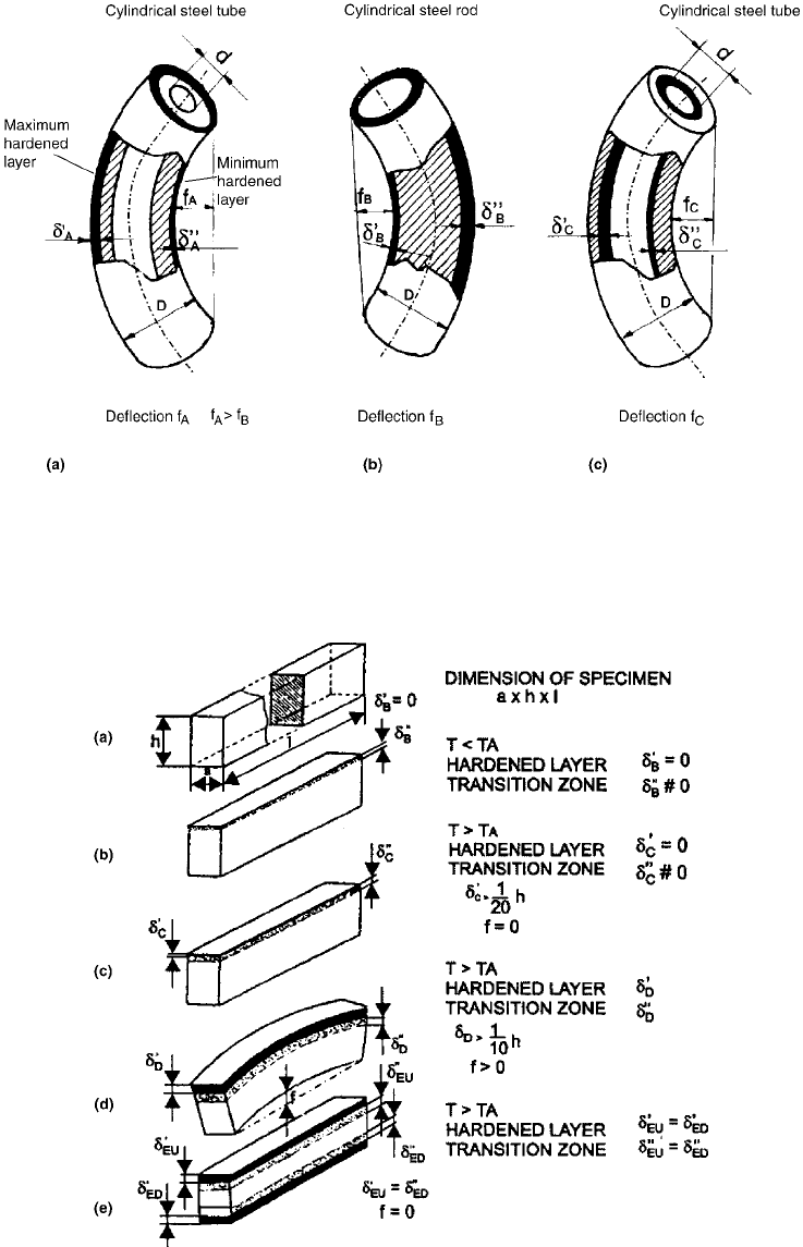
Fig. 66
Influence of nonuniform thickness of surface-hardened layer on distortion for cylindrical steel rod and tube. Source:
Ref 15, 27
Fig. 67
Bending of a steel rod of rectangular cross section as a function of the thickness and location of the hardened layer. Source:
Ref 15
Induction Hardening / 467
Name ///sr-nova/Dclabs_wip/Failure_Analysis/5113_417-501.pdf/Chap_13/ 18/8/2008 4:02PM Plate # 0 pg 467