Canale L.C.F., Mesquita R.A., Totten G.E. Failure Analysis of Heat Treated Steel Components
Подождите немного. Документ загружается.

strength can be noted. Gears heat treated in this
way are suitable for highly loaded machine parts
(Ref 28–30).
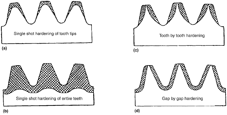
Figure 9(c) shows hardening of individual
gear teeth, where the coil encircles the tooth and
the individual teeth are heated in turn and
quenched directly after heating. In the case of
large-module gears, simultaneous heating of the
left and right flank of the same gear tooth can be
performed (Fig. 9d).
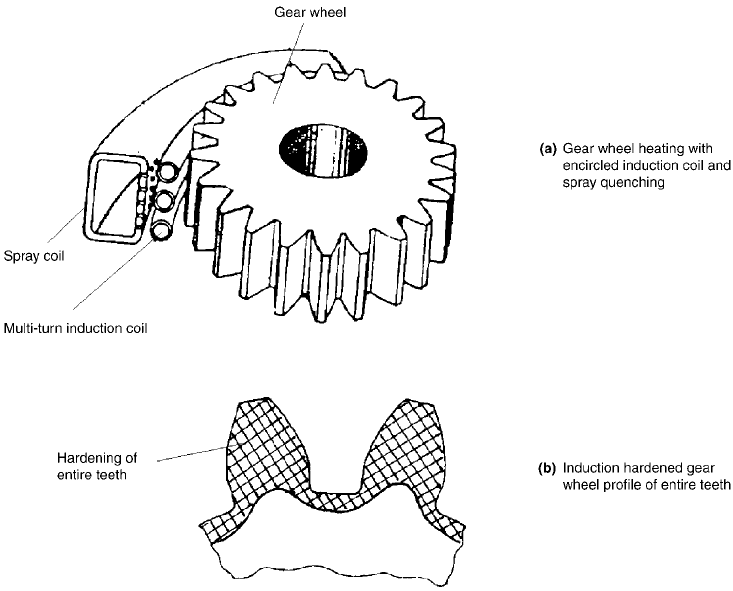
Induction hardening of all gear teeth (Fig. 10)
can be done only for gears with a module smaller
than 3 mm and a gear diameter up to 100 mm.
This kind of hardening requires high-power
frequency generators, for example, 200 kW.
For gears exposed to higher loads, where
refinement of the whole tooth is desirable, a
power of 30 to 40 kW and longer heating times
can be selected.
To ensure a desired penetration depth and
profile of the induction-hardened layer, the fol-
lowing heat treatment parameters can be varied
in a single-shot or progressive induction hard-
ening by choosing a suitable power density and
feed rate:
The size and shape of the induction coil
adapted to the workpiece
Kind of steel and its thermal properties
Size and mass of the workpiece on the
location where induction hardening is to be
performed
Quenching agent and method of quenching
A number of graphs and nomographs are
available for this purpose, offering a selection of
heat treatment conditions for heating and cool-
ing. The most important data are the starting
point data on energy input and frequency of the
current, and the temperature to achieve in
induction hardening. From these data, the time
necessary for heating, in the case of single-shot
hardening, or the feed rate of the workpiece or
the rate at which the coil should move along the
workpiece can be defined (Ref 2, 18–20, 23, 27,
31, 32).
Figure 11(a) illustrates induction surface
heating with a medium-and high-frequency
current. The procedure is known as double-
frequency heating (Ref 27). Here, the gear is first
placed into the coil fed by the medium-
frequency current. Then, the gear is moved into
the high-frequency coil, where only the surface
layer of the gear tooth is reheated with a high-
frequency current. When both phases are com-
pleted, the gear is dropped or moved into a
quenching bath. In this method of heating with a
double frequency, the progressive motion of the
workpiece can be combined with additional
rotation.
Additional rotating motion ensures a uniform
reheating of the surface layer and results in
uniform microstructural changes on the left and
right side of the tooth. In this way, undesirable
and nonuniform dimensional deviations be-
tween the left and right tooth flanks are pre-
vented. The same method of induction surface
Fig. 9 Different methods of induction surface hardening of gear wheels. Source: Ref 15, 16
428 / Failure Analysis of Heat Treated Steel Components
Name ///sr-nova/Dclabs_wip/Failure_Analysis/5113_417-501.pdf/Chap_13/ 18/8/2008 3:59PM Plate # 0 pg 428
heating is shown in Fig. 11(b), where the same
coil is used for heating with a medium- and high-
frequency current (Ref 27).
The second method is hardening of individual
gear wheels or individual gear gaps. Figure 12
shows induction heating of a gear wheel tooth-
by-tooth and Fig. 13 shows induction heating
with the gap-by-gap method. In both methods,
the tooth surface is first heated with the induc-
tion coil and then quenched with a specially
adapted spray system.
Figure 14 shows the shape and position of the
massive inductor placed around the gear tooth
(Ref 27). The coil is shaped so that the gap
between the coil and the tooth surface varies.
Only in this way is it possible to ensure a uni-
form thickness of the layer in the middle and on
the edge of the tooth (Ref 33–37).
Difficulties with this method of gear wheel
hardening occur when the tooth gaps are too
small and the coil heats up the adjacent flank.
This method of induction surface heating of gear
teeth is often not appropriate, since after heating
the adjacent tooth, the next step does not ensure
the desirable hardness of the adjacent tooth. To
avoid this, special protection made of thin cop-
per sheets is used to prevent heating of the
adjacent tooth flanks. The conditions are pre-
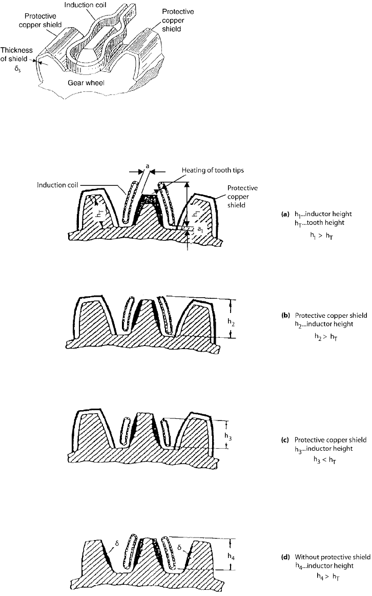
sented in Fig. 15(a–c) (Ref 27). In addition to
protecting adjacent tooth flanks, the shape of
the coil around the tooth has other effects. By
changing the shape and position of the coil
around a particular tooth, it is possible to achieve
equal hardened layer profiles, as in the case of
single-shot hardening. The thickness of the
hardened layer is at a maximum at the tooth
tip and then gradually decreases toward the tooth
root. In Fig. 15(c), the coil is placed slightly
lower, heating only the tooth flank along
the entire height from the root to the tip.
Figure 15(b) shows the lowest position of the
coil while still reaching below the tip of the
tooth. The coil positioned in this way does
not heat the tip of the tooth but only the surface
of the tooth flank from the tip to the root and
yields maximum thickness of the hardened layer
in the middle of the tooth. In this case, too, small
gears are heated with a high-frequency current,
Fig. 10 Single-shot surface induction hardening of gear wheel tooth tips
Induction Hardening / 429
Name ///sr-nova/Dclabs_wip/Failure_Analysis/5113_417-501.pdf/Chap_13/ 18/8/2008 3:59PM Plate # 0 pg 429
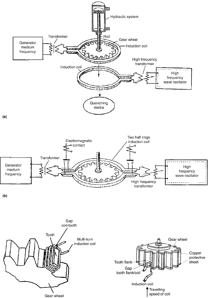
Fig. 11 Induction heating system for gear wheel heating by double frequency (medium/high). Source: Ref 27
Fig. 12
Tooth-by-tooth induction surface heating process of
installing the induction coil around the gear wheel
tooth for heating, followed by shifting spray quenching
Fig. 13
Gap-by-gap gear wheel induction surface heating by
moving the induction coil for heating and moving or
installing spray quenching
430 / Failure Analysis of Heat Treated Steel Components
Name ///sr-nova/Dclabs_wip/Failure_Analysis/5113_417-501.pdf/Chap_13/ 18/8/2008 3:59PM Plate # 0 pg 430
whereas large-sized gears are first heated with a
medium-frequency current, and then heating is
performed with a high-frequency current (Ref 2,
16, 18, 19, 27, 32).
The third method of induction surface hard-
ening is appropriate for large gear modules and
is known as tooth-gap hardening, which belongs
to the progressive hardening methods. In this
case, the coil is placed so that it ensures a uni-
form gap between the coil and the flanks of
two adjacent teeth. The tooth-gap hardening
method is very demanding and requires much
Fig. 14
Relative position of the massive induction coil to the
gear wheel tooth at induction heating. Source: Ref 27
Fig. 15 Influence of induction coil height on profile of induction heating surface layer in an individual tooth. Source: Ref 27
Induction Hardening / 431
Name ///sr-nova/Dclabs_wip/Failure_Analysis/5113_417-501.pdf/Chap_13/ 18/8/2008 3:59PM Plate # 0 pg 431
experience and knowledge to achieve the
desirable properties of the gear.
This method is also known as contour hard-
ening. It is an ideal method for heat treatment of
gears, because it increases the hardness on the
tooth surface only slightly while decreasing the
load-bearing capacity in the root of the tooth.
Gears heat treated in this way exhibit very good
behavior in operation, because compressive resi-
dual stresses are present in the root of the tooth.
Gears with induction-hardened flanks, given that
the dimensioning is carefully carried out, can
achieve the highest fatigue strength. To verify
the results of induction surface hardening, it is
necessary to take certain measures for control-
ling the quality of the hardened layer. For this
purpose, hardness and microhardness measure-
ments, supported by microstructural analysis,
are commonly used. A disadvantage of this pro-
cedure is that, due to the method of heating and
quenching (nonuniformly overheated left and
right tooth flank), slightly higher dimensional
deviations may be obtained than in the case of
simultaneous hardening of both flanks of the
same tooth (Fig. 15d) (Ref 27).
Metallurgical Aspect of Induction Surface
Heating. Prior to transformation hardening,
an operator should calculate the processing
parameters for the given power system. The pro-
cedure is as follows. Some of the processing
parameters are chosen, some calculated. The
choice is usually left to the operator and his
experience. Optimization is then based only on
the selection of power density and scan speed.
The correctly set parameters of transformation
hardening ensure the right heating rate, heating
to the right austenitizing temperature, T
A
3
, and a
sufficient austenitizing time, t
A
. Consequently,
with regard to the specified depth of the hard-
ened layer, a temperature a little higher than the
transition temperature, T
A
3
, should be ensured.
Because of a very high heating rate, the equili-
brium diagram of, for example, steel, is not
suitable; therefore, it is necessary to correct the
existing quench temperature with reference to
the heating rate. Thus, with higher heating rates,
a higher austenite transformation temperature
should be ensured in accordance with a time-
temperature-austenitizing (TTA) diagram.
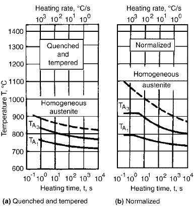
The diagram in Fig. 16(a) is such a TTA
diagram for 1053 steel in the quenched and
tempered state, whereas Fig. 16(b) is for the
same steel in the normalized state (Ref 38).
Because the steel shows a pearlitic-ferritic
microstructure, a sufficiently long time should
be ensured to permit austenitizing. In fast heat-
ing, austenitizing can be accomplished only
by heating the surface and subsurface to an
elevated temperature. For example, with a
heating time, t, of 1 s, for total homogenizing,
a maximum surface temperature, T
s
, of 880
C
should be ensured in the first example and a
much higher surface temperature, 1050
C, in
the second example. This indicates that ap-
proximately 170
C higher surface temperature,
DT
s
, should be ensured in the second example
(normalized state) than in the first example
(quenched and tempered state).
Figure 17 shows a space TTA diagram
including numerous carbon steels with different
carbon contents. The TTA diagram gives par-
ticular emphasis to the characteristic steels, that
is, 1015, 1035, 1045, and 1070 steels, and their
variations of the transition temperature, T
A
3
,
with reference to the given heating rate and the
corresponding heating time (Ref 38). Such a
temperature difference ensures, with regard to
the heating and cooling conditions of the speci-
men, the time required for austenite homo-
genizing, t
A
, in the given depth.
Figure 18 shows a shift of the transformation
temperature, which ensures the formation of
inhomogeneous and homogeneous austenite
within the selected interaction times (Ref 39).
A shorter interaction time will result in a
slightly higher transformation temperature, T
A
1
,
and also a higher transformation temperature,
Fig. 16
Time-temperature-austenitizing diagram for steel
1053 in various states. Source: Ref 38
432 / Failure Analysis of Heat Treated Steel Components
Name ///sr-nova/Dclabs_wip/Failure_Analysis/5113_417-501.pdf/Chap_13/ 18/8/2008 3:59PM Plate # 0 pg 432
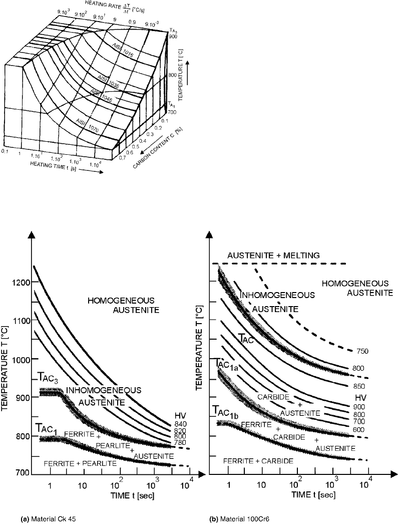
T
A
3
. To ensure the formation of homogeneous
austenite with shorter interaction times, con-
siderably higher temperatures are required.
Figure 18(a) shows a temperature-time diagram
for austenitizing of Ck 45 steel.
The isohardnesses obtained at different in-
teraction times in heating to the maximum
temperature ensure that partial or complete
homogenizing of austenite is plotted.
Figure 18(b) shows the same temperature-time
diagram for austenitizing of 100Cr6 hyper-
eutectoid alloyed steel.
The diagram indicates that with short inter-
action times, which in laser hardening vary
between 0.1 and 1.0 s, homogeneous austenite
cannot be obtained; therefore, the micro-
structure consists of austenite and undissolved
carbides of alloying elements that produce a
relatively high hardness, even up to 920 HV
0.2
.
After common quenching of this alloyed steel
at a temperature of homogeneous austenite, a
considerably lower hardness, only 750 HV
0.2
,
but a relatively high content of retained austenite
were obtained. Retained austenite is unwanted,
since it will produce unfavorable residual
stresses and reduce wear resistance of such a
material.
Fig. 18 Temperature-time-austenitizing diagrams with lines of resulting hardness for various steels. Source: Ref 39
Fig. 17
Influence of heating rate and carbon content
on austenitic transformation temperature. Source:
Ref 38
Induction Hardening / 433
Name ///sr-nova/Dclabs_wip/Failure_Analysis/5113_417-501.pdf/Chap_13/ 18/8/2008 3:59PM Plate # 0 pg 433
The distribution of residual stresses in heat
treatment procedures where only the surface of
the workpiece is heated (induction hardening,
flame hardening) differs greatly from the pro-
cedures where heating is performed throughout
the entire volume (nitriding, cementation). In
nitriding and cementation, the aforementioned
second layer in the subsurface does not appear at
all, because the direction of the heat flow is
opposite to the direction of the heat flow in
induction and flame hardening. The resultant
operating tensile stresses on the surface or in the
surface layer can thus be considerably smaller.
Due to the surface hardness, induction and flame
hardening lowers the fatigue strength of mach-
ine components; therefore, care should be taken
to diminish all detrimental effects in the surface
layer.
A typical example of induction surface hard-
ening is surface hardening of gears that are
heated with a low heating rate and relatively low
current frequency. The outer hardened zone in-
cludes almost the entire height of the gear teeth,
whereas the second zone is in the tooth root area.
A gear heat treated in this way will meet the
wear-resistance requirements expected of the
gear tooth, while the strength of the other part of
the tooth is of minor importance. The fatigue
strength in this case will be relatively low due to
high tensile residual stresses in the tooth root,
that is, in the second zone where the operating or
load tensions and the tensile residual stresses are
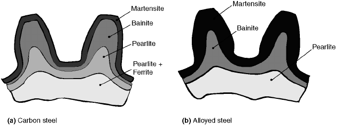
summed up. Figure 19 shows another example
of an induction-hardened gear where the fre-
quency of the current was so high that the gear
tooth is heated along the flank surface and tip, as
is the case in cementation. The energy input in
heating a gear tooth or the whole gear was such
that the second zone has not shown up. A similar
heat treatment can be applied to the spline inside
the gear. A gear heat treated in this way is more
resistant to wear and corrosion and should have
high resistance to fatigue in bending because of
a smaller thickness of the layer in the second
zone.
Many induction-hardened gears are treated in
the tooth gap, that is, in simultaneous heating
and subsequent quenching of two adjacent
flanks of the left and right tooth of the gear with a
hardened root area. In view of the variety of
methods to induction harden gears and the other
possible ways of gear hardening, it is unwise to
make a hasty decision in selecting the procedure.
It is necessary to make a thorough analysis,
including answers about the expected quality of
the hardened layer and analysis of the operation
loads of the machine components.
Highly loaded gears can be successfully
induction hardened if a high-frequency current
and high-input power are used. High frequency
is necessary in order to obtain a sufficient thick-
ness of the hardened layer on the tooth flanks and
a fine hardened layer in the tooth root area. A
high-input power is necessary to increase the
heat gradient, which makes the size of the sec-
ond zone smaller, resulting in a thinner second
layer with tensile residual stresses.
On gears with a small diameter, the induction-
hardening equipment should be able to harden
the gear throughout its volume. Induction hard-
ening of entire gears has some advantages, such
as rapid heating, no danger of decarbonization
and oxidation, high productivity, and repeat-
ability in the gear quality. Thus, the hardened
layer is only defined by the first zone to the depth
that is greater than the height of the gear tooth.
Fig. 19
Typical examples of induction surface hardening of (a) carbon steel and (b) alloyed steel gears produced from carbon steel (a)
and alloyed steel (b)
434 / Failure Analysis of Heat Treated Steel Components
Name ///sr-nova/Dclabs_wip/Failure_Analysis/5113_417-501.pdf/Chap_13/ 18/8/2008 3:59PM Plate # 0 pg 434
In induction hardening and quenching, lowering
or even the disappearance of compressive resi-
dual stresses is achieved in the tooth root area,
causing a considerable decrease in fatigue
strength and a higher propensity for fatigue.
In flame heating, lower temperature gradients
are reached than in induction heating. This
results in increased thickness of the layer in the
second zone. Possible harmful effects due to the
disappearance of the second zone of the hard-
ening layer can be avoided by heating the entire
gear, which is possible to do in commonly used
furnaces.
When the induction coil has stopped heating,
an austenitic microstructure in the surface layer
should be obtained. Then, the cooling process
for the austenitic layer begins. To accomplish
martensite transformation, it is necessary to
ensure a critical cooling rate that depends on
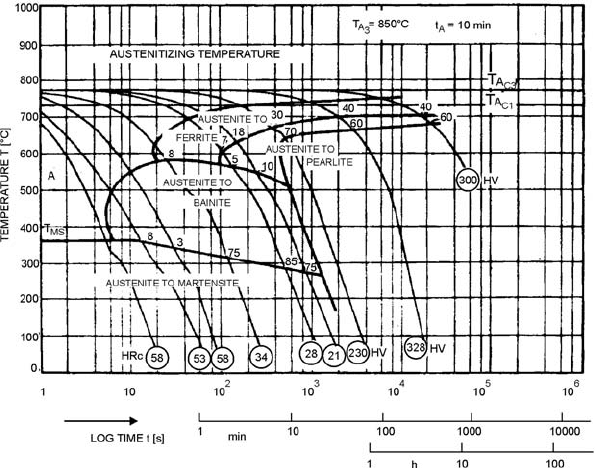
the material composition. Figure 20 shows a
continuous cooling transformation diagram
for EN19B steel, including the cooling curves
(Ref 38).
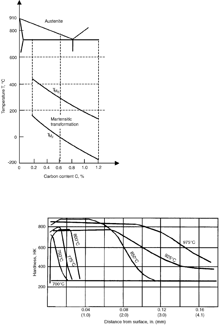
Because carbon steels have different carbon
contents, their microstructures also show differ-
ent contents of pearlite and ferrite. An increased
carbon content in steel decreases the tem-
perature of the beginning of martensite trans-
formation, T
M
S
as well as of its finish, T
M
F
Figure 21 shows the dependence between
carbon content and the two martensite transfor-
mations (Ref 38).
Consequently, an increase in carbon content
in steel results in the selection of a lower critical
cooling rate. In general, the microstructures
formed in the surface layer after transformation
hardening can be divided into three zones:
A zone with completely martensitic micro-
structure
A semi-martensitic zone or transition
microstructure
A quenched and tempered or annealed zone
with reference to the initial state of steel
Transformation hardening of steel starts
from its initial microstructure, which is ferritic-
pearlitic, pearlitic-ferritic. or pearlitic. In steel
heating, transformation into a homogeneous
austenitic microstructure should be ensured.
Figure 22 shows the dependence of the maxi-
mum surface temperature obtained in induction
heating with a machine part made of steel with
0.8% C and a pearlitic microstructure (Ref
40, 41). How the through-depth heating of the
machine part will proceed depends on the maxi-
mum surface temperature obtained and the
power density, which means that the through-
depth hardness profiles will differ.
Fig. 20 Continuous cooling transformation diagram of EN19B steel. Source: Ref 38
Induction Hardening / 435
Name ///sr-nova/Dclabs_wip/Failure_Analysis/5113_417-501.pdf/Chap_13/ 18/8/2008 3:59PM Plate # 0 pg 435
With the same power density, this means that
a higher maximum surface temperature will be
accomplished with a longer heating time. Since
the heating times are usually short, austenitic
grains have little time left to grow. It can be
assumed that the grains remain fine and do not af-
fect through-hardenability, that is, the through-
depth hardness profile. The diagram shows the
heating conditions that provide, in all cases, a
completely homogeneous austenitic microstruc-
ture to a certain depth and, consequently, con-
stant hardness. Then follows a transition zone
consisting of homogeneous austenite and some
inhomogeneous austenite and pearlite. Conse-
quently, hardness in the transition zone will
gradually decrease to that of the parent metal. It
will be approximately 240 HK. It is important
that the transition zone consists of a mixture
showing different ratios of the microstructures
concerned. The different microstructure ratios in
the transition zone, however, define the hardness
profile in this zone. Thus, at the maximum sur-
face temperature, a maximum hardness of ap-
proximately 700 HK, without a constant part
with homogeneous martensite, is obtained, and
then it decreases immediately to the hardness of
the parent metal.
With a maximum temperature of 800
C,
there will be constant hardness to a depth of
0.6 mm; from that point to a depth of 0.85 mm,
the hardness will slowly decrease to that of the
parent metal, that is, 240 HK. The highest
hardness, 850 HK, is obtained with the max-
imum austenitizing temperature, 850
C, and is
found to a depth of 1.10 mm. From that point
to a depth of 2.70 mm, the hardness slowly
decreases to that of the parent metal. With higher
maximum surface temperatures, the lowest
Fig. 21
Influence of carbon content in steel according to start
and finish temperature of martensitic transformation
Fig. 22
Hardness profiles for an induction-hardened 0.8% C steel for various maximum temperatures. The initial microstructure of
the steel was pearlite. Source: Ref 40, 41
436 / Failure Analysis of Heat Treated Steel Components
Name ///sr-nova/Dclabs_wip/Failure_Analysis/5113_417-501.pdf/Chap_13/ 18/8/2008 4:00PM Plate # 0 pg 436
hardness is obtained at the surface, and then,
with a greater depth, it slowly decreases. With
steel having a pearlite-ferrite or ferrite-pearlite
microstructure, a microstructure consisting not
only of inhomogeneous martensite but also of
pearlite-ferrite grains will occur in the transition
zone. Such a microstructure results in a stronger
decrease in hardness than with the steel having a
pearlite microstructure. It is essential for effi-
cient induction surface hardening that constant
hardness is obtained to a sufficient depth and that
the hardness profile of the transition zone is
adequate. It is only in this way that notch defects
in the hardened layer may be prevented and
better operation of the machine part under
dynamic load may be ensured.
Magnetic Flux Concentrators
In induction surface heating, unwanted areas
on the workpiece are often heated or even hard-
ened. This type of problem appears when the
shape of the product surface is very complex,
and it is therefore difficult to adjust the coil for
local heating and quenching. For more de-
manding shapes, shields from materials with
good heat conductivity, for example, copper, are
often used on the product to prevent heating of
the workpiece. Heating the copper shield pre-
vents undesirable heating of certain areas as well
as loss of heat. Such an example can be seen in
Fig. 15, which shows the protection of two ad-
jacent heat flanks while heating the tooth in the
middle with an induction coil (Ref 15, 19–21,
28, 42).
Heat losses occur due to local heating of the
workpiece surface that is not to be hardened;
however, this is done because it is not possible
to adjust the shape of the induction coil.
The heating temperature is higher than the
hardening temperature, so that after quenching,
unwanted increased surface hardening is ob-
tained. In cases of treatment of two local surface
areas on the workpiece that are in direct pro-
ximity, if heat is applied two times in sequence,
the heating of the second area may result in
tempering of the previously treated area. In these
cases, the area hardened first may have a tem-
pered microhardness with a lower hardness.
Therefore, research has been done on how to
form and adapt the coil to offer a more con-
centrated magnetic flux. By adjusting the con-
centration of the magnetic flux, it is possible to
achieve localized heating of only those areas on
the workpieces that are to be hardened. In the
last decade, the development of induction coils
has been directed toward achieving localized
concentration of magnetic flux (Ref 19, 21). The
purpose of magnetic flux concentration is to
improve the efficiency of surface heating and
reduce heat losses. The use of a magnetic flux
concentrator enables selective local heating on
workpiece/product areas with complex geo-
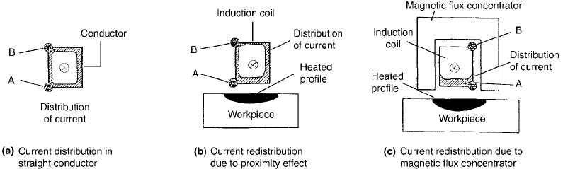
metry. Figure 23 shows a straight conductor with
current density distribution in points “A” and
“B” for three cases (Ref 19, 42):
Current density distribution in a straight
conductor (Fig. 23a)
Current density distribution in a straight
conductor when the conductive material
(workpiece) is approached (Fig. 23b). The
current density is greater in point “A”, closer
to the workpiece material, than in point “B”.
As a result, the workpiece is locally heated
over a longer length—longer than the width
of the conductor. This is referred to as current
redistribution due to the proximity effect.
Fig. 23
Current distribution in an inductor without/with a magnetic flux concentrator and its effect on the heating profile of the
workpiece. Source: Ref 19, 42
Induction Hardening / 437
Name ///sr-nova/Dclabs_wip/Failure_Analysis/5113_417-501.pdf/Chap_13/ 18/8/2008 4:00PM Plate # 0 pg 437