Canale L.C.F., Mesquita R.A., Totten G.E. Failure Analysis of Heat Treated Steel Components
Подождите немного. Документ загружается.

hardness across the entire hardened layer and the
microhardness in the very thin surface layer, the
latter were measured by the Vickers method.
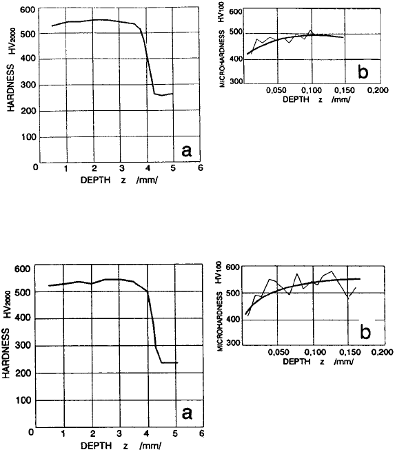
Thus, Fig. 83 and 84 show the hardness profiles
versus the induction-hardened layer depth
according to Vickers at a load of 20 N or mea-
surements of microhardness according to Vick-
ers in a very thin surface layer to a depth of
150 mm at a load of 2 N (Ref 44).
The hardness of the surface layer after
induction surface hardening is very uniform in
all the investigated main bearing locations and
equals approximately 520 to 550 HV
2.0
. The
hardness profile highly conforms to the residual-
stress profile, which is confirmed by a decrease
in hardness in the transition zone. The hardness
profile in the transition area is likewise very
steep and points to high stress concentrations in
this location when the crankshaft is in the loaded
state.
Figure 83 presents the hardness profile in
an induction surface-hardened layer to a depth
of 5.0 mm and the microhardness profile to
a depth of 150 mm on bearing location “A”
(Ref 44).
The hardness measurements show that the
quenched and tempered steel has a hardness of
approximately 220 to 260 HV
2.0
, and the sur-
face-hardened layer has a hardness of approxi-
mately 540 HV
2.0
. In the surface-hardened
layer, a slight increase in hardness as a function
of depth is evident, which is conditioned by
microstructural differences due to varied cool-
ing rates of the surface layer. The surface is
cooled under the effects imposed by the cooling
medium, yet at a greater depth, the effects of the
medium are accompanied by a more expressed
effect of the cold mass of the core, resulting in
the formation of very fine martensite and greater
hardness at greater depth (Ref 64).
Fig. 83
Hardness profile in the induction surface-hardened layer and microhardness profile in a very thin surface layer for bearing
location “A”. Source: Ref 44
Fig. 84
Hardness profile in the induction surface-hardened layer and microhardness profile in a very thin surface layer for bearing
location “C”. Source: Ref 44
478 / Failure Analysis of Heat Treated Steel Components
Name ///sr-nova/Dclabs_wip/Failure_Analysis/5113_417-501.pdf/Chap_13/ 18/8/2008 4:03PM Plate # 0 pg 478
Kosel and Kosec (Ref 67) conducted an
investigation on the cracks formed at the
surface-hardened and ground bearing location
of a crankshaft. Crankshafts are made of high-
quality chromium-molybdenum heat treatable
steel. The shafts were forged from square shafts
with a cross-sectional area of 120 by 140 mm. In
the course of mechanical and heat treatments,
the workpieces were tested with various non-
destructive methods, for example, visual
inspection, and, if required, magnetic particle
and/or penetrant inspections. A peculiarity of
shaft production is that during forging, the
material flows from the middle of a slab ingot to
the outer section of a forging due to plastic
deformation. The steel in the middle is usually of
lower quality than the steel at the surface of a
cast iron-works blank and that of a formed steel-
works semiproduct. The character of forming
the steel-works semiproduct tool, steel-works
blank, and crankshaft was such that a reverse
material flow occurred from the middle to the
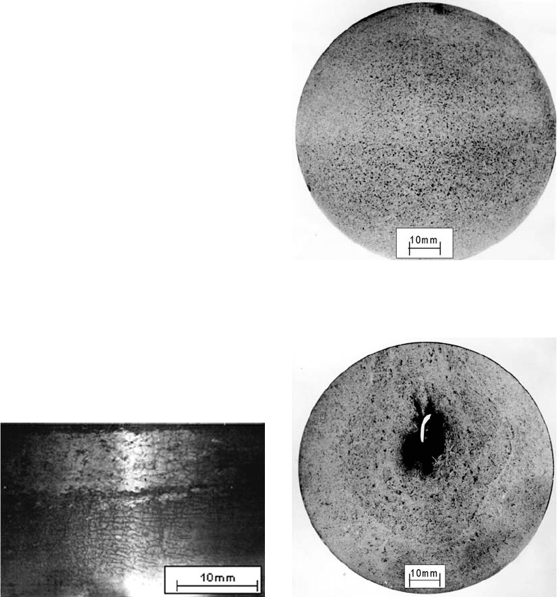
surface. The authors reported the presence of
weblike cracks at the surface of the crankshaft
bearing location (Fig. 85) and gave two reasons
for the occurrence of cracks immediately after
forging (Ref 67):
Inhomogeneity, that is, nonuniform cross-
sectional chemical composition of steel
Inadequate conditions of bearing-location
grinding
After macrostructural and microstructural
examinations as well as a microchemical ana-
lysis were performed, it was found that, from the
metallurgical point of view, the forging showed
quality, and the defect may be attributed to the
grinding process alone. Figure 86 shows a
macrosection of the forging at the bearing, and
Fig. 87 shows a forging made of low-quality slab
ingot (Ref 67).
The main purpose of the investigation was to
find the cause of the weblike cracks after
induction surface hardening and the final
grinding on the bearing location on the crank-
shaft. Grinding was studied in the same way as at
the cut-out bearing locations. From the steel-
works slab ingots prepared for forging, speci-
mens of a suitable length were cut out and turned
to size.
Fig. 85
Weblike surface cracks at bearing location of
crankshaft. Source: Ref 67
Fig. 86
Macrograph of etched favorable billet cross section.
Source: Ref 67
Fig. 87
Macrograph of etched unfavorable billet cross
section. Source: Ref 67
Induction Hardening / 479
Name ///sr-nova/Dclabs_wip/Failure_Analysis/5113_417-501.pdf/Chap_13/ 18/8/2008 4:03PM Plate # 0 pg 479
The specimens prepared in this way were
hardened and tempered at 560
C and then sur-
face hardened, with a maximum surface tem-
perature ranging between 820 and 900
C. The
case depth ranged between 3 and 4 mm.
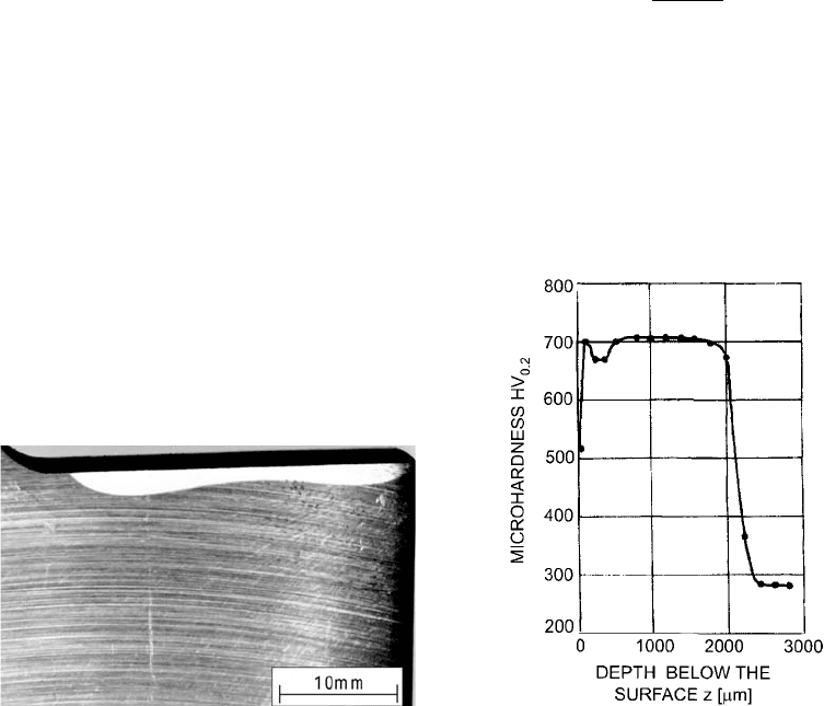
The macrograph in Fig. 88 clearly identifies
the bearing location and shows a considerable
difference in case depth. Generally, it was found
that:
There were insignificant differences in che-
mical compositions.
There were segregations in the central part of
the crankshaft.
There were shrinkage cavities mainly on the
inside and also on the outside part of the
forging.
There were microsegregations.
Some of the hardened bearing locations
showed dimensional variations with refer-
ence to the anticipated thickness.
The microhardness obtained at the surface
was within the expectations and somewhat
above a value of 700 HV
2.0
.
The depth of the hardened bearing locations
ranged between 2.0 and 2.5 mm.
No differences in the microstructures could
be found using a common optical micro-
scope analysis or a scanning electron micro-
scope.
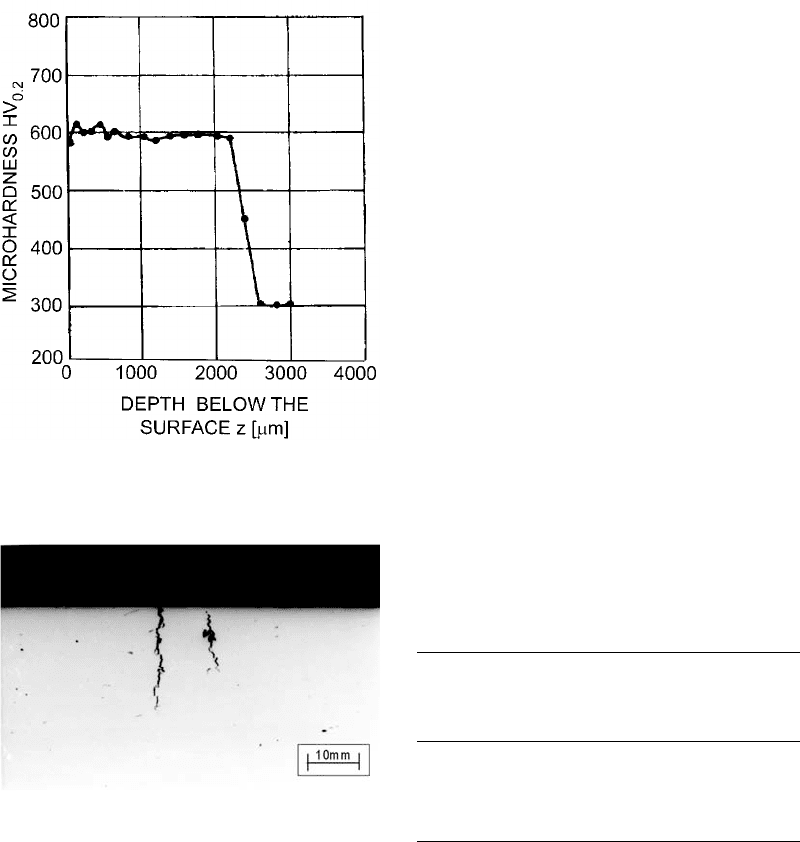
The microhardness at the cracked cylindrical
specimens was somewhat lower, approxi-
mately 600 HV
2.0
.
Figure 89 shows the microhardness profile
of the cross section of an induction-hardened
layer for a favorable bearing location, and
Fig. 90 shows the profile for an unfavorable
bearing location without cracks (Ref 67).
Figure 91 shows two temperature cracks, with
a pore at the crack location being visible as well.
An analytical model was elaborated to clearly
demonstrate the causes of crack formation at the
hardened surface after grinding (Ref 67).
The stress condition, s
R
, occurring at the
hardened-layer surface after heat treatment and
grinding was known. In several cases, the sur-
face-hardened layers took the shape of an
eccentric ring, which means a nonuniform thick-
ness of the hardened layer. The cracks occurred
at the location of the smallest layer thickness. As
expected, residual stress occurs at the specimen
surface where cracks initiate when stress oc-
curs due to phase transformation to martensite,
thermal stresses during hardening, stresses due
to martensitic tempering during grinding, and
thermal stress after grinding (Ref 67).
In the phase transformation from austenite to
martensite, steel volume will increase. The vol-
ume strain can be calculated using the equation:
e
V
=
V
M
7V
A
V
A
where V
M
is the volume of an elementary cell of
martensite, which can be calculated for the given
steel:
V
M
=(2:861 0:013% C)
2
(2:861+0:116% C)
=23:7262 10
3
nm
3
Fig. 88
Macroscopic examination of case depth at cross
section of crankshaft bearing. Source: Ref 67
Fig. 89
Hardness characteristic at cross section of weblike
cracked neck as a function of depth, z. Source: Ref 67
480 / Failure Analysis of Heat Treated Steel Components
Name ///sr-nova/Dclabs_wip/Failure_Analysis/5113_417-501.pdf/Chap_13/ 18/8/2008 4:03PM Plate # 0 pg 480
and V
A
is the volume of an elementary cell of
austenite of the same steel:
V
A
=0:5(3:548+0:044% C)
3
=22:68242 10
3
nm
3
then e
V
= 0.046.
A stress condition with such a volume strain
would exceed the material strength. Table 3
indicates that the smallest hardened-layer thick-
ness required is obtained under the condition
that the resulting stress shall be higher than the
breaking stress, according to Hook’s model, and
no cracks occur at the workpiece surface after
grinding (z
min
= 2.873 mm) (Ref 67).
Using the proposed analytical model, the
researchers (Ref 67) evaluated the magnitude of
stresses in steel after surface hardening and
grinding. They found a mutual dependence of
the hardened-layer profile and the resistance
against material cracking during grinding.
Cracks will appear at the surface of those
bearings in which short overheating of steel
occurred and the hardness in a narrow zone
decreased strongly during grinding. In such
cases, through hardenability of a material
reaches a depth of 150 mm, where tempered
martensite will form. The thickness of the
surface-hardened layer with all the cracked
bearings was approximately 2.0 mm, which
indicated that an appropriate model was chosen.
Fatigue Strength of Materials
A heat treatable AISI 4140 steel was used
for manufacturing crankshafts. This steel is
very appropriate for statically and dynamically
loaded parts of car engines and machines
because of its high hardness achieved after hard-
ening (57 HRC). The steel is characterized by
good hardenability and is thus suitable for manu-
facturing machine parts with large cross sections
in which a very high strength can be obtained
after refinement. After tempering, the steel does
not show a tendency to brittleness, and therefore,
no special heat treatment procedures are re-
quired. This steel is also suitable for surface
hardening (flame surface hardening, induction
surface hardening) and displays a very good
resistance to wear.
However, special attention must be paid to the
part design phase, and great care should be given
to the design of radius and transition areas
to prevent notch effects under dynamic loads.
The steel is adapted for use in a wide range of
Fig. 91
Thermal cracks in surface-hardened neck section.
Source: Ref 67
Table 3 Minimum case depth required for no
cracks at workpiece surface
Excentricity
of hardened
layer
(e), mm
Depth
(z), mm
Temperature
prior to
quenching
used in
Hook’s model
(T
K
), °C
Yield
stress of
martensite
R
K
0:2,(T
K
)
,
N/mm
2
Resultant
stress after
hardening
and grinding
(s
R
(T
0
)),
N/mm
2
0.594 3.156 343 1123 1306
0.709 3.0412 336 1144 1327
0.877 2.873 325 1177 1360
1.146 2.6045 307 1232 1414
Source: Ref 67
Fig. 90
Hardness characteristic of neck cross section without
cracks as a function of depth, z. Source: Ref 67
Induction Hardening / 481
Name ///sr-nova/Dclabs_wip/Failure_Analysis/5113_417-501.pdf/Chap_13/ 18/8/2008 4:03PM Plate # 0 pg 481
temperatures, and it preserves high toughness
even at low temperatures (Ref 44, 68, 69).
Impact tests provide useful quantitative com-
parative data with relatively simple test speci-
mens and equipment. However, these tests do
not provide property data for design purposes for
material sections containing cracks or defects.
Data of this type are obtained from fracture
mechanics, in which theoretical and/or experi-
mental ways determine the fracture of structural
materials containing pre-existing cracks and
defects.
The number of cycles to failure (N) obtained
by the S-N curve under load or a stress-control
condition is related to the total life of the part up
to failure. Fatigue cycles throughout the life of
the machine part consist of crack initiation and
its propagation. Crack propagation refers to
stable crack growth up to the crack instability.
The S-N curve approach does not separate the
crack initiation phase from propagation. Indus-
trial experts assume that the crack has already
initiated in the machine part, and only the total
number of cycles associated with the propaga-
tion are of interest. Existing or initiated cracks
assumed in the machine part are the result of
dynamic load cycles induced during manu-
facturing, prior to its use. The size of the pre-
existing crack can be assumed based on the
capability of suitable inspection. The expert may
assume an initial surface crack after testing and
makes a decision about the application of the
part.
Using the available initial defects in the
material, the total life of the part can be assessed
by an appropriate fracture mechanics method.
Basic factors affecting the shape of the S-N
curve are:
Materials selection and heat treating or cold
working conditions
Various types of loading on the specimen,
such as tension, compression, torsion, or a
combination
Loading conditions described by medium
stress, amplitude stress, and frequency
Influences on the environment carried by
temperature, corrosion, and other factors
Some major factors that affect the strength of
a metal include:
Stress concentration: Fatigue strength is
greatly reduced by the presence of stress
raisers, such as notches, holes, keyways, or
sharp changes in cross sections.
Surface roughness: In general, the smoother
the surface finish on the metal sample, the
higher the fatigue strength.
Surface condition: Since most fatigue fail-
ures originate at the metal surface, any major
change in the surface condition will affect
the fatigue strength of the metal.
Environment: If a corrosive environment is
present during the cyclic stress of a metal,
the chemical attack greatly accelerates the
rate at which fatigue cracks propagate.
During machining processes, various defects
occur on the surface, such as small scratches and
grooves, and are introduced into the workpiece
surface. Typical failures are moving machine
parts, such as shafts, connecting rods, and gears.
It is estimated that failures of machine parts in
machines contribute approximately 80% of
fatigue failures. These surface detects can limit
the fatigue life. Improving the surface finish by
polishing will increase fatigue life significantly.
One of the most effective methods of in-
creasing fatigue life is the existence of residual
compressive stresses in a thin surface layer.
Thus, applied surface tensile stress will be par-
tially reduced in magnitude by the residual
compressive stress. The net effect is the prob-
ability of crack formation and a consequent re-
duction in fatigue failure.
According to the AISI standard, the heat
treatable structural steel 4140 contains between
0.38 and 0.45% C, 0.90 and 1.2% Cr, and 0.15
and 0.30% Mo. It has very high hardenability,
contributing to high strength values in products
with high mass. Molybdenum yields a desirable
fine microstructure after hot working as well as
heat treatment, contributing to a good strength-
to-toughness ratio. Due to its fine-grained
microstructure, it also reaches a relatively high
toughness in the heat treated condition.
The strength of the steel as well as its sur-
face hardness and wear resistance may be in-
creased by heat treatment and thermochemical
treatment.
Mechanical properties of steel having a dia-
meter of up to 40 mm and between 40 to
100 mm are given in Table 4.
Tensile strength of the steel varies between
880 and 1080 N/mm
2
, and a minimum tough-
ness value, r
3
, equals approximately 41 J. The
steel is very sensitive to notch and transition
on machine parts subjected to fatigue loading.
Fatigue strength of the material is lowest under
torsional load, s
T
, and varies for the diameters
482 / Failure Analysis of Heat Treated Steel Components
Name ///sr-nova/Dclabs_wip/Failure_Analysis/5113_417-501.pdf/Chap_13/ 18/8/2008 4:03PM Plate # 0 pg 482
mentioned, that is, 16 to 40 mm, so that
s
T
= 285 N/mm
2
, and for diameters from 40 to
100 mm, s
T
= 255 N/mm
2
. Fatigue strength
under torsional load is three or four times lower
than the tensile strength of steel under static
load, according to the data in the table.
In professional literature, data on fatigue
strength of materials are usually presented for a
prescribed specimen shape and size that has
been adjusted to the testing device. Specimens
for fatigue strength are usually of cylindrical
shape, with a smaller diameter in the middle part
and a rounded transition into the larger-diameter
part. The latter is then usually clamped for
testing. Modes of loading the specimens vary but
are usually either torsion, bending, or tension/
compression. The highest fatigue strength is
displayed by a specimen subjected to bending
loads (Ref 27, 36). For other modes of loading,
the relation with bending fatigue strength, s
wb
,
is expressed empirically, that is, fatigue strength
in torsion, tw, is 0.58 s
wb
, or fatigue strength in
tension/compression, s
wz
, is 0.70 s
wb
.
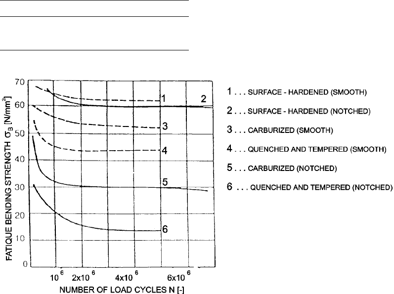
Figure 92 presents curves for different modes
of dynamically loaded specimens made from
various steels that had been heat treated in
assorted ways (Ref 15). From among six curves,
four represent specimens made from heat trea-
table steel and two for cementation steel speci-
mens. The heat treatable steel is Cr-Mo-Ni steel
with 0.37% Ni, and the specimens were heat
treated in two different ways:
Surface hardening applied to specimens with
a smooth shape (curve 1) and specimens
with a slot (curve 2)
Quenching or tempering applied to smooth
specimens (curve 4) and specimens with a
slot (curve 6)
The cementation steel is a chromium-nickel
steel with 0.15% C, where the specimens were
smoothly shaped (curve 3) and slotted (curve 5).
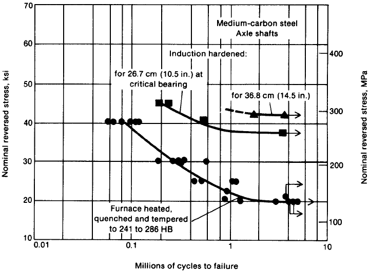
Axle shafts used in cars, trucks, and farm
vehicles are, with few exceptions, surface hard-
ened by induction. Although a portion of the
hardened surface is used as a bearing in some
axles, the primary purpose of induction hard-
ening is to put the surface under a state of com-
pressive residual stress (Ref 45). By this means,
the bending and torsional fatigue life of an axle
may be increased by as much as 200% over that
for parts conventionally heat treated (Fig. 93)
(Ref 45).
Table 4 Mechanical properties of heat treated
structural steel 4140
Diameter
(D), mm
Tensile strength
(R
m
), N/mm
2
Yield point
(R
p0.2
), N/mm
2
Extension
(A
5
), %
Toughness
(r
3
), J
16–540 980–1180 769 11 41
40–5100 880–1080 635 12 41
Source: Ref 15
Fig. 92 Graphs of the fatigue strength of surface-hardened and carburized specimens. Source: Ref 15
Induction Hardening / 483
Name ///sr-nova/Dclabs_wip/Failure_Analysis/5113_417-501.pdf/Chap_13/ 18/8/2008 4:03PM Plate # 0 pg 483
Induction-hardened axles consist of a hard
surface, high-strength core, and tough outer case
with good torsional strength and a tough, ductile
core. Many axles also have a region in which the
case depth is kept very shallow, so that the part
can be readily straightened following heat
treatment. In addition to substantially improving
strength, induction hardening is also very cost-
effective. This is because most shafts are made
of inexpensive, unalloyed medium-carbon steel
that is surface hardened to case depths of 2.5 to
8 mm, depending on the cross-sectional size. As
with crankshafts, typical hardness (after tem-
pering) is approximately 50 HRC. Such hard,
deep cases improve yield strength considerably
as well (Ref 45).
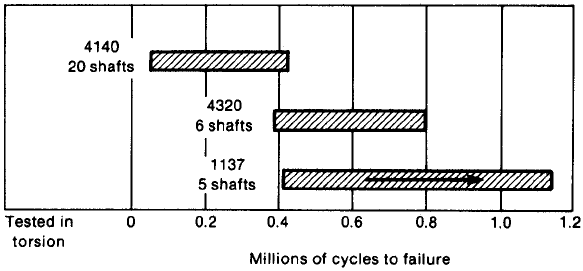
Modern transmission shafts, particularly
those for cars with automatic transmissions, are
required to have excellent bending and torsional
strength, as well as surface hardness for wear
resistance. Under well-controlled conditions,
induction-hardening processes are able to satisfy
these needs, as shown by the data in Fig. 94,
which compares the fatigue resistance of
through-hardened axles (Ref 45). The induction-
hardening methods employed are varied and
include both single-shot and scanning techni-
ques.
The hardness achieved on the surface of the
hardened specimens was 56 to 59 HRC and on
the cemented specimens, 58 to 59 HRC. To test
the effects of the slot on fatigue strength, a slot
of equal size and shape was made on all the
specimens, whether they were quenched or
tempered, hardened or cemented. It was made
in the middle of the cylindrical specimen to an
equal depth of 0.4 mm. The depth on the sur-
face-hardened and cementation specimens was
1.5 mm. The results of testing showed that there
are significant differences in terms of heat
treatment methods and that the highest fatigue
strength was found in surface-hardened speci-
mens.
A comparison of the fatigue testing results
showed that:
In surface-hardened specimens with a
smooth cylindrical shape and with a slot, the
difference in the achieved fatigue strength is
minimal. This can be attributed to a very de-
sirable distribution and size of compressive
residual stresses throughout the hardened
Fig. 93
Bending fatigue response of furnace-hardened and induction-hardened medium-carbon steel tractor axles. Shaft diameter:
70 mm. Fillet radius: 1.6 mm. Source: Ref 45
484 / Failure Analysis of Heat Treated Steel Components
Name ///sr-nova/Dclabs_wip/Failure_Analysis/5113_417-501.pdf/Chap_13/ 18/8/2008 4:03PM Plate # 0 pg 484
layer. Since the depth of the slot reaches only
one-quarter of the hardened surface layer,
the size of compressive residual stresses at
the slot is still very high, so that the weak-
ening due to the slot and stress concentration
along the slot does not cause any essential
drop in fatigue strength.
In quenched and tempered specimens with
no earlier prestressing of the surface layer,
the fatigue strength was considerably lower
than in surface-hardened specimens. The
fatigue strength of quenched and tempered
specimens with a slot was also remarkably
lower. The results show that the difference in
fatigue strength in slotted induction surface-
hardened specimens and slotted quenched
and tempered specimens is 5 to 1.
Smooth cemented specimens displayed 25%
lower fatigue strength than the surface-
hardened specimens of the same shape,
whereas the cemented specimens with a slot
displayed 50% lower fatigue strength than
the same surface-hardened specimens.
The question arises about what the fatigue
strength is in those specimens where the slot
reaches deeper than the hardened layer. A
regular problem in these cases is crack
occurrence and propagation of cracks start-
ing from the slot. Due to the shape of the
specimen and the slot, stresses start con-
centrating at these places, depending on the
type and size of external loads. It should not
be forgotten that there are no compressive
residual stresses along the slot, and the size
of tensile stresses along the slot plays a
decisive role in crack occurrence.
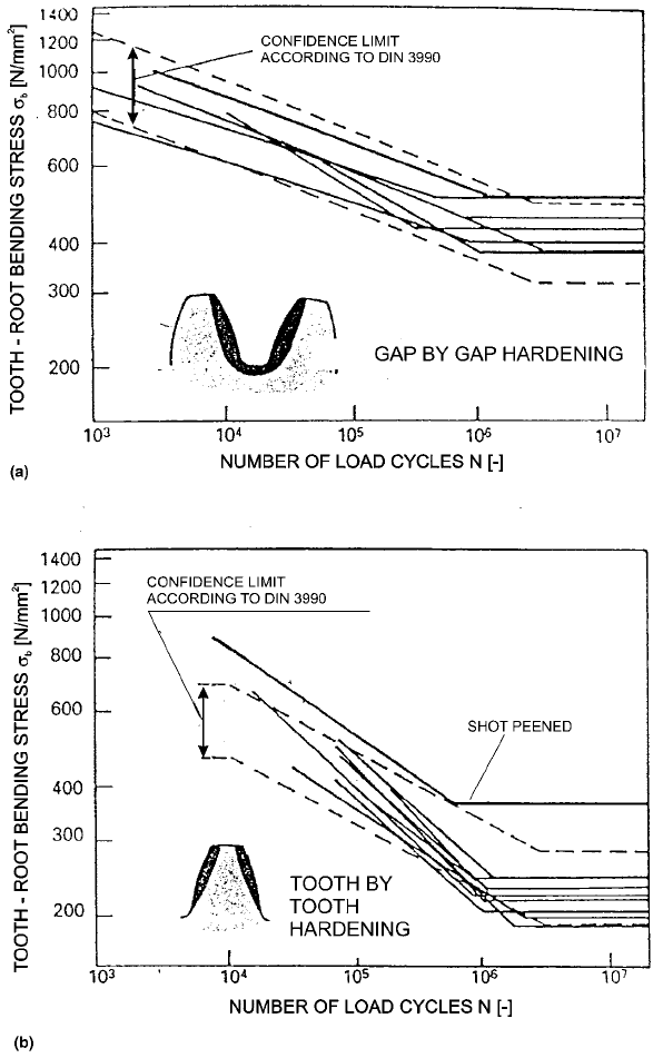
Figure 95 shows bending stress in a tooth root
subjected to dynamic load versus the number of
oscillations (Ref 36). Figure 95(a) shows the
bending stress for induction surface hardening
of adjacent flanks of two teeth with a coil
reaching into the tooth gap. In the process, the
tooth flank as well as the tooth root are hardened
(Ref 36). This kind of heat treatment of gears
from steels for induction surface hardening
provides a fatigue bending strength in the range
of 320 to 490 N/mm
2
. Figure 95(b) shows the
same relationship when the induction coil
encircles an individual gear tooth. In this pro-
cess, the tooth flank is hardened, and the micro-
structure and hardness in the tooth root are
preserved (Ref 36). A result of this method of
hardening is that the fatigue strength is drasti-
cally lowered to values ranging from 200 to
300 N/mm
2
for the entire range of steels suitable
for induction surface hardening. This is a con-
siderable drop in fatigue strength for the material
in the tooth root (Ref 45, 70).
Stress Profiles in Machine Parts in the
Loaded State
Heat treatment engineers must be very careful
in choosing the conditions of induction surface
hardening in order to benefit from the distribu-
tion of residual stresses achieved in dynamically
loaded parts. In industrial practice, induction
surface hardening should satisfy the requirement
of fatigue resistance of machine components.
The main reason for this worsening of the
properties of the machine part is attributed to
tensile residual stresses in the hardened layer
and undesirable hardness distribution in the
transition zone from the hardened into the
unhardened part of the subsurface. These effects
Fig. 94
Comparison of fatigue life of induction surface-hardened transmission shafts with that of through-hardened and carburiz ed
shafts. Arrow in lower bar (induction-hardened shafts) indicates that one shaft had not failed after testing for the maximum
number of cycles shown. Source: Ref 45
Induction Hardening / 485
Name ///sr-nova/Dclabs_wip/Failure_Analysis/5113_417-501.pdf/Chap_13/ 18/8/2008 4:03PM Plate # 0 pg 485
are quite natural, and in the first phase are a
result of very rapid local heating of the thin
surface layer, while in the second phase this is
accompanied by forced quenching, which
ensures a critical cooling rate and the occurrence
of a martensitic microstructure. Both phases in
induction surface hardening can increase the risk
of fatigue, especially if the latter is assessed only
from the point of view of surface hardness. To
successfully estimate the quality of the hardened
layer, one must select the optimal synergetic
effects between the input electric energy and the
interdependence between the induction coil and
the workpiece surface, connected with the
Fig. 95
Bending fatigue strength of gear teeth at (a) tooth gap hardening and (b) flank hardening for various steels. Broken lines denote
confidence limit according to DIN 3990. Source: Ref 36
486 / Failure Analysis of Heat Treated Steel Components
Name ///sr-nova/Dclabs_wip/Failure_Analysis/5113_417-501.pdf/Chap_13/ 18/8/2008 4:03PM Plate # 0 pg 486
occurrence of eddy currents in the workpiece
surface layer that leads to heating. Due to com-
plex synergetic effects in induction heating
or hardening, it is necessary to carefully study
each influence on the properties of the hardened
surface layer (Ref 27, 45). Fatigue strength
in machine components that have been induction
surface hardened is increased if the total sum
of the load tensions and residual stresses in
the surface layer is of a compressive nature.
To ensure the highest fatigue strength of a com-
ponent, it is necessary to provide the follow-
ing:
In dynamically loaded components, the
surface is prone to fatigue occurrence, so the
surface must have the highest compressive
stresses.
If the total sum of stresses, that is, load ten-
sion plus residual stresses on the surface, is
always of a compressive nature, then there is
no chance for the occurrence of cracks and
crack growth.
To ensure good behavior of the surface and
the hardened surface layer in the loaded
condition, it is necessary to induce a suitable
prestressing in the surface layer. This can be
achieved by a carefully selected heat treat-
ment method that would create the highest
compressive residual stresses on the surface
and a desirable profile of the latter in the
hardened subsurface layer.
Induction surface hardening offers opportu-
nities to ensure a considerable amount of
compressive stresses in the machine com-
ponent surface and to ensure restrained
transformation of compressive surface
stresses into tensile residual stresses in the
subsurface layer.
The endurance of machine components sub-
jected to bending and torsion loads can be suc-
cessfully increased by ensuring sufficiently high
compressive residual stresses. A manufacturing
goal is to create a sufficient amount of com-
pressive residual stresses with a favorable dis-
tribution, since this is the only way to increase
the reliability of components in operation. An
early failure of a component in operation may
cause catastrophic damage on a machine and
thus a loss in profit. A decisive role in the oc-
currence of residual stresses is played by the
synergetic effects between the heat treatment
method, the type of material, and the shape of the
workpiece. For this reason, heat treatment must
be treated from the point of view of heating,
overheating, and cooling/quenching as well as
the internal stresses created at a certain point
during the treatment. During heat treatment,
internal stresses are created by the temperature
differences and phase transformations between
the core and the surface, which are a result of the
volume differences between the core and the
surface. The created volume differences
between the core and the surface then give rise to
internal stresses. During the process of heating
and cooling, internal stresses may produce the
following effects:
When internal stresses are lower than that of
the yield point, higher residual stresses are
induced by heat treatment in the workpiece,
but these would not cause distortions,
cracks, or failure.
During a certain moment in heat treatment,
internal stresses exceed the yield point,
which leads to distortions and lower residual
stresses in the workpiece.
During very detrimental conditions in heat
treatment, internal stresses are higher than
the tensile strength of the material, causing
the workpiece to crack and creating larger
distortions and high residual stresses.
Numerous changes that take place in the
hardened surface layer of the workpiece are
always a result of the heating and quenching
conditions. Therefore, it is necessary to study the
events taking place in the workpiece directly
after the hardening temperature is reached.
Three zones are distinguishable in a workpiece
heated to the hardening temperature (Fig. 96a):
the first zone, where the outer layer is heated to
the hardening temperature; the second zone,
which is heated below the hardening tempera-
ture between the temperatures T
A
1
and T
A
3
for
rapid heating; and the third zone, where the
temperature is lower than T
A
1
(Ref 15).
Heating to the hardening temperature at a
certain depth is followed by quenching. Quen-
ching results in the occurrence of compressive
residual stresses (Fig. 96b), when the familiar
transformations in the hardened layer take place.
The second layer does not suffer the same dis-
tortions as the surface layer, although the heat-
ing there has been sufficient enough to improve
the properties of the material. In the second
layer, hardening is incomplete, which, in com-
parison with the first layer, results in lower
hardness and strength of the material.
Induction Hardening / 487
Name ///sr-nova/Dclabs_wip/Failure_Analysis/5113_417-501.pdf/Chap_13/ 18/8/2008 4:03PM Plate # 0 pg 487