Canale L.C.F., Mesquita R.A., Totten G.E. Failure Analysis of Heat Treated Steel Components
Подождите немного. Документ загружается.

factor given by:
c=c
n
=exp(As
ys
1=2
Bs
ys
)
A={2(1+n)V=3RT}{2E=p}
1=2
B={2(1+n)V=RT}{2=p}
where c is the hydrogen concentration at the
crack tip, c
n
is the hydrogen concentration in the
bulk steel, n is Poisson’s ratio, V is the partial
molar volume of hydrogen in iron, E is the
elastic modulus, and s
ys
is the yield strength.
For a high-yield-strength steel having s
ys
=
1000 MPa, the solubility of hydrogen in steel
increases by a c/c
n
factor of 6.5. The tip of a
crack is an excellent site for hydrogen accumu-
lation, because the strain is greater than that
associated with s
ys
.
Although the mechanism for HAC is still
debated, equations to prevent HAC have been
developed empirically. For example, the preheat
parameter (P
w
) and the hydrogen accumulation
parameter (P
HA
), were developed from experi-
mental work in Japan by Yurioka et al. (Ref 15,
41) as practical tools to empirically predict a
preheating temperature to prevent HAC:
P
w
=P
cm
+H
D
=60+R=40,000
where P
cm
is the Ito-Bessyo (Ref 42) carbon
equivalent given as:
P
cm
= C+Si=30+(Mn+Cu+Cr)=20+Ni=60
+Mo=15+V=10+5B
where H
D
is the diffusible hydrogen content
in mL/100 g, elements are in weight percent,
and R is the restraint intensity in MPa. The HAC
can be avoided if the value of P
w
50.3. In the
P
w
equation, the effects of alloy composition,
hydrogen content, and restraint are taken into
account empirically.
Consumables manufacturers have recognized
that filler metals containing less carbon than the
steel plate would produce not only enhanced
weld metal toughness at required strength levels
but also greater resistance to HAC. In fact, vir-
tually all of the older algorithms for determin-
ing preheating temperatures were based on the
composition of the base metal and not the weld
metal. Cracking of the HAZ by HAC was so
common in structural steels that it was assumed
that the coarse-grainced HAZ would always be
the location of maximum susceptibility to
cracking. Using the advantages of modern low-
carbon steels and consumables, Nippon Steel
(Ref 4) designed a series of commercial low-
carbon steels for line pipes that could be welded
while maintaining high strength and toughness
with equally low-carbon filler metals. These
pipeline steels included the X-65, X-70, and
X-80 grades, which contain very low carbon
(50.03%), high manganese for strength and to
control the bainite transformation, and 0.001%
boron to suppress the proeutectoid ferrite nucle-
ation at austenite grain boundaries. It is desirable
to have a large amount of acicular ferrite in the
weld metal for optimal strength and toughness as
well as good resistance to HAC (Ref 43, 44).
Microconstituents detrimental to weld metal
toughness and possibly increased susceptibility
to HAC include grain-boundary ferrite, mar-
tensite, and side-plate ferrite, because these
structures provide a continuous path for cleav-
age crack propagation.
Types of Hydrogen-Assisted Cracking
Hydrogen-assisted cracking can appear in
four common forms:
Underbead or delayed cracking
Weld metal fisheyes
Ferrite vein cracking
Hydrogen-assisted reduced ductility
As mentioned earlier, the mechanism of HAC
is not clear, but management of hydrogen and
the prevention of HAC are well established.
Preheating the weld area prior to and during
welding provides the most reliable resistance to
HAC. There are many empirically-derived
methods to calculate preheat temperatures to
prevent HAC. All of the various types of HAC
can be avoided by good welding practice. The
forms of HAC are discussed in the following
sections.
Underbead or Delayed Cracking
By far, the most common form of HAC is
underbead or delayed cracking, schematically
illustrated as discontinuity 12g in Fig. 1 and
described in Table 1. Typically, this form of
cracking occurs in the coarse-grained HAZ up to
72 h after the weld has cooled. This is because
the HAZ typically has higher carbon content and
Failure Analysis of Steel Welds / 509
Name ///sr-nova/Dclabs_wip/Failure_Analysis/5113_503-519.pdf/Chap_14/ 18/8/2008 4:06PM Plate # 0 pg 509
generally a higher carbon equivalent level than
the weld metal. Even though the source of
hydrogen is virtually always from the welding
consumable, atomic hydrogen rapidly diffuses
to crack nucleation sites in the HAZ. The dif-
fusion of hydrogen explains the time-dependent
nature of HAC, thus the name delayed cracking.
The coarse-grained HAZ is the zone adjacent to
the weld and represents a region that has been
heated to nearly the melting temperature, fol-
lowed by rapid cooling. Because of its higher
carbon content and large austenite grain size, the
coarse-grained HAZ develops a significantly
higher hardness than the weld metal. The HAZ
will transform to martensite upon cooling if the
carbon equivalent is high enough. Since the
harder HAZ is more susceptible to HAC than
either the weld metal or the unaffected base
metal, the cracking in a butt weld is typically
confined to a narrow strip of metal immediately
adjacent to the weld bead. Cracking in fillet
welds occurs at the toe of the weld because that
is the location of highest stress concentration.
Toe cracking is schematically illustrated as
discontinuity 12e in Fig. 1 and described in
Table 1.
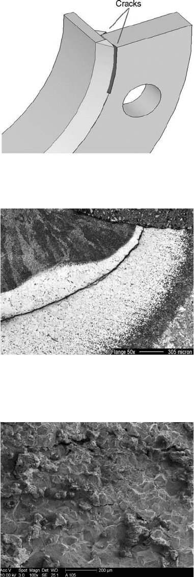
Example 5: Underbead Cracking. Cross-
country line pipe is welded continuously for
long distances. At regular intervals, a flange
needs to be welded onto the pipe for coupling to
a valve or other device. Recently, a section of
pipe was removed from service because of
cracking that had occurred in the toes of the fillet
welds joining the flange to the pipe. The pipe
was 203 mm (8 in.) outside diameter by 6.4 mm
(0.25 in.) wall thickness, and the flange was
205 mm (8.1 in.) inside diameter by 305 mm
(12 in.) outside diameter by 18 mm (0.71 in.)
thick. Since the pipe was only 6.4 mm thick, the
weld was not preheated. Cracks measuring
approximately 10 cm long developed at the toes
of the fillet welds on the flange side, as shown in
Fig. 6.
From the illustration in Fig. 6, the cracking
occurred only in the toes of the two fillet welds
on the flange side. No cracking was observed at
the toes of the two fillet welds on the pipe side. A
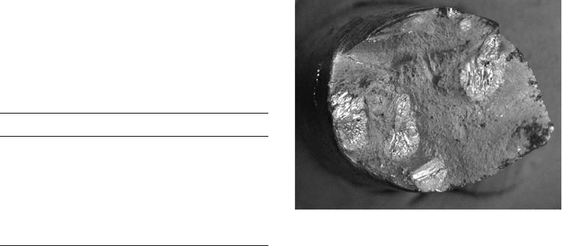
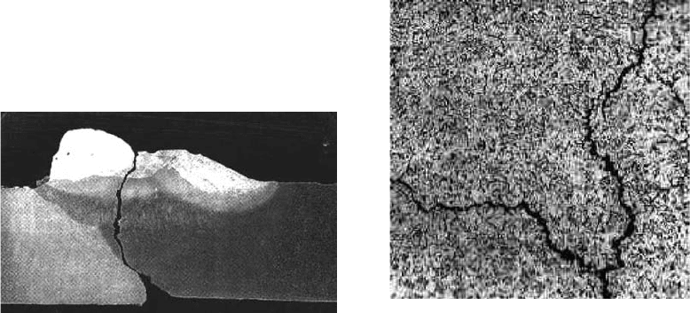
metallographic section of the crack, shown in
Fig. 7, clearly reveals that the crack was con-
fined to the brittle martensitic HAZ on the flange
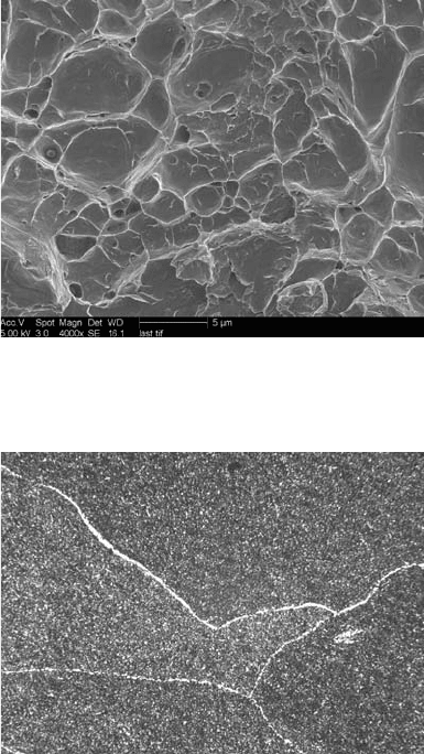
side. Scanning electron microscopy of the
cracked area clearly shows an intergranular
mode of fracture (Fig. 8). Chemical analysis of
the pipe and flange in Table 3 revealed that an
incorrect steel was used for the flange. The
Fig. 6
Underbead cracking at the toe of the fillet weld on the
flange
Fig. 7
Toe cracking on the flange side of the flange-to-pipe
fillet weld, showing the weld metal, heat-affected
zone, and unaffected base metal. Cracking occurred in the mar-
tensitic (white) heat-affected zone of the flange.
Fig. 8
Fracture surface of flange failure in the as-received
condition. Intergranular fracture is shown as well as
debris retained from the field.
510 / Failure Analysis of Heat Treated Steel Components
Name ///sr-nova/Dclabs_wip/Failure_Analysis/5113_503-519.pdf/Chap_14/ 18/8/2008 4:06PM Plate # 0 pg 510
correct flange steel was supposed to be a low-
carbon steel. Instead, the flange was a 0.8%
(high) carbon steel, which was very susceptible
to HAC in the HAZ when welded without pre-
heating.
Cracking in the HAZ on the flange side of the
fillet weld was due to the mistaken use of a high
0.8% C steel instead of the specified low-carbon
steel. Quality control measures need to be fol-
lowed to prevent mixed steels from being used.
Weld Metal HAC and Fisheyes
Welding of modern low-carbon steels often
results in HAZs with greater resistance to HAC.
Thus, the weld metal composition is now as
susceptible as the HAZ. If the weld metal con-
tains sufficient diffusible hydrogen content, has
high yield strength, and is in a highly stressed
condition, the susceptibility of such weld metal
to HAC is very possible. For example, in
the line-pipe industry, new thermomechanical-
controlled processing steels achieve high yield
strength through thermal processing in the roll-
ing mill, so that the carbon content and carbon
equivalent levels for a given yield strength have
dropped substantially. With this reduction in
carbon equivalent, the susceptibility to HAZ
cracking has also declined significantly. Since
the as-deposited weld metal achieves strength
primarily through alloying, the weld metal is
now very susceptible to HAC. Often, field
welding of X-65 and X-70 line pipe is performed
with high-hydrogen E8010G cellulosic elec-
trodes. In this case, the weld metal yield strength
is greater than both the HAZ and unaffected base
metal. Thus, the weld metal has become the
weak link and is most susceptible to HAC.
The strong influence of hydrogen on weld
metal cracking can be observed in tensile testing
and bend testing as well as in failures of welds
subject to slowly applied tensile stress. Fisheyes
occur typically on the fracture surface of steel
all-weld-metal tensile specimens that fail due to
HAC. In tensile testing, fisheyes reduce the weld
metal ductility measurements, such as percent
elongation and percent reduction of area. Fish-
eyes are local areas within the weld that are more
hardenable due to solute banding, cellular, or
dendritic segregation of alloying elements (Ref
45). These initiation areas may also be richer in
localized hydrogen due to their proximity to
hydrogen traps such as inclusions. Since these
alloy-rich segregated areas are more susceptible
to brittle HAC, small, localized brittle-fracture
zones appear visually on a tensile test fracture
surface as bright round spots surrounded by gray
ductile fracture. The bright round spot may
consist of a local region of typically inter-
granular or possibly cleavage fracture sur-
rounded by ductile dimpled failure. Both
intergranular and cleavage failures are brittle
fracture modes that appear much more brightly
than the surrounding material, which is ductile
dimpled and gray-appearing.
Example 6: Fisheyes on Fracture Sur-
face. A high-strength steel, HSLA-100, was
butt-welded with a matching-strength filler
metal using gas metal arc welding (GMAW) and
argon-5%CO
2
shielding gas at a heat input of
1.1 kJ/mm (28 kJ/in.) without preheating. The
filler metal contained Fe-0.03%C-1.4%Mn-
3%Ni-0.7%Mo. Because of the very low carbon
content, the weld metal hardness did not exceed
24 HRC. Tensile test results showed inadequate
ductility of only 8% elongation.
Upon examining the fracture surface of the
tensile specimen, multiple fisheyes were
observed, as shown in Fig. 9. An SEM image of
Table 3 Chemical analysis of the flange and pipe
Chemical
element Flange Pipe
C 0.80 0.07
Mn 0.67 1.10
Si 0.25 0.24
Ni 0.01 0.01
Cr 0.23 0.01
S 0.13 0.005
P 0.018 0.017
Al ... 0.038
Nb ... 0.02
Fig. 9
Brittle fisheyes appear as bright spots in a gray ductile
matrix.
Failure Analysis of Steel Welds / 511
Name ///sr-nova/Dclabs_wip/Failure_Analysis/5113_503-519.pdf/Chap_14/ 18/8/2008 4:06PM Plate # 0 pg 511
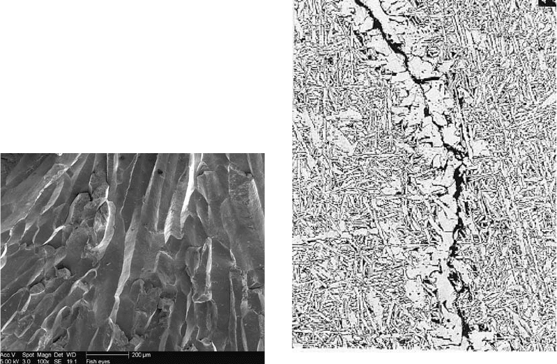
the center of a bright fisheye exhibited brittle
intergranular fracture, as shown in Fig. 10. The
SEM images outside of the fisheyes showed
ductile dimpled microvoid coalescence. Welds
were repeated to determine the amount of dif-
fusible hydrogen in similar welds in accordance
with AWS A4.3 (a standard welding test for
diffusible hydrogen). Despite the fact that
GMAW is known as a very low-hydrogen pro-
cess, the value obtained for diffusible hydrogen
was 9 mL/100 g, which was far greater than
expected. It was found that the filler metal
manufacturer used excess hydrocarbon-base
lubricant during the wire-drawing operation
because of the high strength of the wire.
Fisheyes were caused by excessive amounts
of diffusible hydrogen in the weld metal due to
the lubricant residue on the filler metal.
Ferrite Vein Cracki ng
A very unexpected form of HAC is ferrite
vein cracking, which can occur in slowly cooled
electroslag welds. In recent studies of electro-
slag welding of 50 and 75 mm thick low-carbon
steel at Portland State University (Ref 46),
ferrite vein cracking of A709-grade 245 steel
occurred only in welds that were made with flux
and/or filler metal known to have high moisture
content. Although the mechanism is not certain,
diffusible hydrogen causes the ferrite at prior-
austenite grain boundaries to crack under the
residual tensile stress produced by contraction
during weld cooling. This is very unusual,
because typical HAC is associated with hard
martensitic microstructures. Ferrite was always
thought to be immune to HAC because of its low
strength and low hardness. It was also found that
nickel alloying additions tended to promote
HAC in the form of ferrite vein cracking, while
an equivalent amount of molybdenum resisted
cracking. Both nickel and molybdenum are
essential alloying elements for enhancing frac-
ture toughness in both the weld metal and base
metal. The mechanism by which nickel and
molybdenum appear to have virtually opposite
effects on susceptibility to HAC is not known.
Example 7: Ferrite Vein Cracking in
High-Heat-Input Welds. Single-pass full-
penetration electroslag welds were deposited on
50 mm (2 in.) thick ASTM A588 steel using a
heat input of 42 kJ/mm (1070 kJ/in.) for bridge
applications. The ASHTO/AWS D1.5 Bridge
Welding Code required both radiographic and
ultrasonic testing (UT) of the completed welds.
The UT revealed possible indications of crack-
ing around the weld center. The weld metal was
sectioned for metallographic examination, and
ferrite vein cracking was found, as shown in
Fig. 11.
Clearly, cracking was confined to the grain-
boundary ferrite, which was nucleated at the
prior-austenitic grain boundaries.
Fig. 10
SEM image of center of fisheye showing intergranular
fracture
Fig. 11
Ferrite vein crack occurring in the prior-austenite
grain boundaries of weld metal deposited on A709-
grade 50W
512 / Failure Analysis of Heat Treated Steel Components
Name ///sr-nova/Dclabs_wip/Failure_Analysis/5113_503-519.pdf/Chap_14/ 18/8/2008 4:06PM Plate # 0 pg 512
Review of the welding procedure revealed
that the flux and tubular wire used in this process
were not baked prior to welding. The unbaked
flux was a source of moisture. Despite its ex-
tremely high weld heat input and the use of mild
steel electrodes, electroslag weld metal has been
shown to be susceptible to HAC. The fabricated
metal-cored tubular wire was also unbaked.
Under the welding heat, moisture in the flux
and filler metal produces atomic oxygen and
hydrogen. Since electroslag welds are large
single-pass deposits, the weld center is under
substantial tensile stress. The combination of
ample diffusible hydrogen and high-shrinkage
tensile residual stress at the weld center provides
the necessary ingredients for ferrite vein crack-
ing. Subsequent welds were made with flux that
was baked to 204
C (400
F) and a new metal-
cored wire that was baked at an elevated tem-
perature prior to shipment. The resulting welds
have since been free of ferrite vein cracking.
Although the mechanism of HAC of grain-
boundary ferrite is unknown, elimination of
cracking was achieved by reducing the sources
of moisture or hydrogen.
Hydrogen-Assisted Reduced Ductility
This form of HAC occurs when the damage
due to diffusible hydrogen is not sufficient to
cause cracking in the weldment but is sufficient
to cause reduced ductility in subsequent tensile
and bend tests. This is a clear illustration of the
principles reported by Beachem (Ref 32) and
shown schematically in Fig. 5. All fracture
modes become more severe with increasing
diffusible hydrogen. Even the ductility asso-
ciated with ductile microvoid coalescence is
substantially reduced in the presence of diffu-
sible hydrogen.
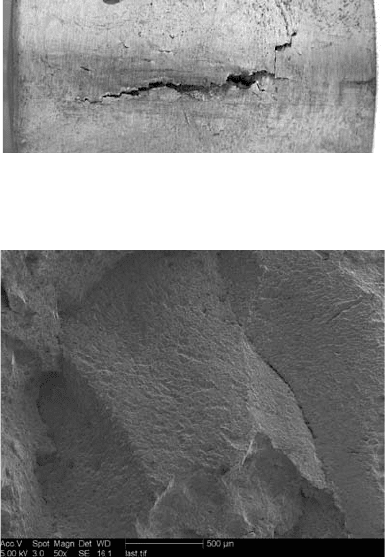
Example 8: Failure to Pass Bend Tests due
to Hydrogen. Multipass submerged arc welds
deposited on 50 mm thick A588 steel were
subject to inspection in accordance with the
AWS D1.1 Structural Welding Code. The fol-
lowing tests were performed for the procedure
qualification welds: tensile testing, bend testing,
Charpy V-notch impact toughness testing, as
well as both ultrasonic and radiographic testing.
All of these tests were passed successfully ex-
cept the guided bend test. As shown in Fig. 12,
the side-bend specimen cracked well before the
prescribed bend radius could be achieved.
Visual inspection and low-magnification op-
tical microscopy of the cracked bend specimen
exhibited an intergranular mode of fracture.
Scanning electron microscopy at 50 · revealed
that the crack propagated intergranularly along
the prior-austenite grain boundaries, as shown in
Fig. 13. However, at approximately 4000 · , the
intergranular fracture surface exhibited shallow
dimples, as shown in Fig. 14. This dimpled
intergranular mode of fracture is due to the
weakness of the ferrite envelopes surrounding
each prior-austenite grain, as shown in Fig. 15.
The presence of diffusible hydrogen caused a
reduction of ductility of grain-boundary ferrite
sufficient to fail the bend test. The Beachem
diagram in Fig. 5 shows that microvoid coales-
cence can also be adversely affected by diffu-
sible hydrogen. Using low-hydrogen practices,
such as baking the flux prior to use, eliminated
the cracking problem during bend testing.
Stress-Corrosion Cracking of Steel
Stress-corrosion cracking of steels is possible
when the steel is subject to both adequate tensile
Fig. 12 Side-bend test failure of weld
Fig. 13
Scanning electron micrograph of fracture surface of
bend failure
Failure Analysis of Steel Welds / 513
Name ///sr-nova/Dclabs_wip/Failure_Analysis/5113_503-519.pdf/Chap_14/ 18/8/2008 4:06PM Plate # 0 pg 513
stress (but below the yield strength) and an
aggressive environment. The absence of one of
these elements will eliminate stress-corrosion
cracking. Welds are particularly good sites for
stress-corrosion cracking, because substantial
tensile residual stresses are always present. The
shrinkage stresses associated with the solidifi-
cation and cooling of welds produce near-yield
tensile residual stresses in and around the weld.
Relatively mild chemical environments can
activate the stress-corrosion cracking process.
Environments known to cause stress-corrosion
cracking of plain carbon and alloy steels include
liquefied ammonia, hydrogen sulfide, molybde-
num disulfide, sodium hydroxide sour gas, high
pH values, nitrate solutions, and many other
corrosive environments. Stress-corrosion crack-
ing of carbon steel can even take place in pure
water under high temperature and pressure.
Although many theories for stress-corrosion
cracking have been suggested, only two appear
to be the basis for such cracking. These are the
stress-sorption theory and the electrochemical
theory.
The stress-sorption theory states that dam-
aging substances in the environment are chemi-
cally absorbed onto the surface of the steel,
causing a reduction in the cohesive bonding
force between iron atoms. Only an atom-thick
surface layer is needed to seriously affect the
bonding forces between surface atoms. There
is a threshold stress necessary to initiate stress-
corrosion cracking. In some ways, this mechan-
ism resembles HAC in steels (discussed earlier),
where only a few ppm of hydrogen in concert
with tensile stress are needed to reduce the
cohesive bonds between iron atoms and cause
cracking. In stress-corrosion studies, acoustic
emission sensors have been attached to the
cracking sample to monitor the propagation of
the crack. Strong acoustic emissions were em-
itted and recorded each time the advancing crack
jumped or burst. Acoustic emission sensors used
to monitor HAC of steel displayed a similar
jump or burst behavior.
The electrochemical theory involves the
setting up of galvanic cells within the micro-
structure of the steel. Anodic dissolution paths
are produced along concentration gradients in
the metal or in grain boundaries. When the grain
boundaries are anodic to the bulk of the metal,
tensile stresses (although below yield) are
necessary to continue the cracking process in
order to open up dissolved pathways for further
penetration by the corrosive environment. As
evidence of the electrochemical nature of this
cracking process, stress-corrosion cracking can
be stopped by applying cathodic protection. As
soon as cathodic protection is removed, stress-
corrosion cracking continues.
Example 9: Stress-Corrosion Cracking of a
Weld. After 30 years in service, a low-pressure
steam supply line developed a reoccurring
cracking problem in a circumferential butt weld.
The weld was on a 25 cm (10 in.) supply line
that carried 0.4 MPa (55 psig), 205
C (400
F)
steam to a paper machine. This line was 30 m
(100 ft) downstream from a spray attemperator
that cooled higher-temperature steam by spray-
ing boiler feedwater into the line.
When cracks were initially discovered, they
were ground out and rewelded. The repair welds
reportedly cracked after only a few days in
service.
Fig. 14
Higher-magnification image of fracture surface in
Fig. 13 showing dimpled intergranular fracture
Fig. 15
Optical microscopy of grain structure of electroslag
weld metal. Original magnification: 50 ·
514 / Failure Analysis of Heat Treated Steel Components
Name ///sr-nova/Dclabs_wip/Failure_Analysis/5113_503-519.pdf/Chap_14/ 18/8/2008 4:06PM Plate # 0 pg 514
A visual examination revealed that neither the
original welds nor the repair welds penetrated
through to the inside of the pipe. The cracking
consisted primarily of circumferential cracks
down the center of the weld. In addition, there
were a few locations where short longitudinal
cracks emanated from the primary circumfer-
ential crack. Macroscopically, the cracks were
generally irregular and branching.
Sections of the cracked region were prepared
for metallographic examination of the weld
geometry and crack morphology, as shown in
Fig. 16. A microhardness scan of the base metal
revealed a hardness of 79 HRB, with a hardness
of 87 to 94 HRB in the original weld. The repair
weld was significantly harder, with a hardness of
22 to 34 HRC.
Metallographic investigations revealed an
intergranular branching morphology, as shown
in Fig. 17. Scanning electron microscopy also
showed the presence of several secondary
branching cracks emanating from the primary
crack. These cracks also proceeded in an inter-
granular fashion. Energy-dispersive spectro-
scopy did not reveal the presence of foreign
materials at the fracture surface in a measurable
quantity.
The pipe fractured due to stress-corrosion
cracking (SCC) precipitated by the presence of
geometric stress concentrations and high resi-
dual tensile stresses in the weld. The SCC is an
environmentally induced cracking mechanism
that can occur in a susceptible material in the
presence of tensile stress and an aggressive
chemical agent. Although the particular agent in-
volved could not be identified, this is not unusual,
because small amounts of a caustic agent can
often cause cracking in the proper conditions.
Due to the location of the cracking, it is likely
that the agent entered the line in the spray
attemperator process. It is likely that an upset in
the chemistry of the boiler feedwater at some
time in the past contaminated the downstream
lines and led to the SCC in this instance.
The consequences of additional steam line
failures need to be evaluated. Given the nature of
the cracking, inspection methods capable of
detecting the cracks in early stages are limited. It
may be most cost-effective to replace the steam
lines downstream of the attemperator and re-
evaluate the methods used for ensuring the
proper chemistry of the boiler feedwater.
Future repairs should ensure complete crack
removal and full penetration welds using proper
preheat and interpass temperatures to minimize
hardness gradients.
Solidification Cracking of Steel
Solidification cracking is one of several forms
of hot cracking. Solidification cracking in steel
and steel alloys occurs near the end of the soli-
dification process and is caused by two dominant
factors: tensile stress acting on the weld during
solidification, and a large temperature range
between the solidus and liquidus temperatures or
the presence of low-melting impurities such as
sulfer and phosphorus. The tensile stress acting
on the weld can arise from either shrinkage
tensile stresses produced during solidification
and cooldown, or externally applied tensile
stress or tensile restraint stress. The effect of the
liquidus-to-solidus temperature range has been
Fig. 16.
Cross section of weld at butt joint. Etchant: 2% nital.
Courtesy of MEI-Charlton, Inc.
Fig. 17
Micrograph of the crack near the weld root. Original
magnification: 100 · . Etchant: 2% nital. Courtesy of
MEI-Charlton, Inc.
Failure Analysis of Steel Welds / 515
Name ///sr-nova/Dclabs_wip/Failure_Analysis/5113_503-519.pdf/Chap_14/ 18/8/2008 4:06PM Plate # 0 pg 515
dealt with generally by several empirical soli-
dification cracking equations. For example,
Matsuda (Ref 47) developed a very popular
parameter for solidification cracking of steels
called L
t
, where increasing L
t
increased sus-
ceptibility to cracking:
L
t
=70(C Si=12 Mn=9+3P+4S+Ni=23
+Cr=35+Mo=70)
where all elements are in weight percent.
Clearly the effects of carbon and alloying
elements such as manganese, molybdenum,
chromium, and nickel were assumed to be linear,
as shown in the L
t
equation. As the L
t
equation
suggests, decreasing carbon content has always
been assumed to decrease solidification cracking
susceptibility in steel weld metal. Prediction
formulas for solidification cracking show
the effect of carbon on cracking to be linear.
However, recent research has shown that the
effect of carbon on solidification cracking of
low-carbon steels is far more complex and
nonlinear than predicted by the L
t
formula.
For example, Masumoto (Ref 48) showed that
solidification cracking was enhanced for carbon
contents 40.1%. Conversely, Ohshita et al. (Ref
41) reported that cracking was enhanced for
carbon 50.1% and that nickel additions were
beneficial in reducing the cracking effect of
carbon, Karjalainen et al. (Ref 49) surveyed the
technical literature and reported that there was a
least-susceptible range of carbon contents
between 0.1 and 0.17%. Within this range, the
cracking susceptibility was minimized. Ichi-
kawa et al. (Ref 50) reported peak solidification
cracking susceptibility at 0.035% C, followed by
enhanced cracking when the carbon content
exceeded 0.1%. Most recently, Kim et al. (Ref
51) and Won et al. (Ref 52) showed a peak
in solidification cracking susceptibility at
approximately 0.10% C. It was apparent from
the literature that the effect of carbon on soli-
dification cracking susceptibility of steel weld
metal required further study.
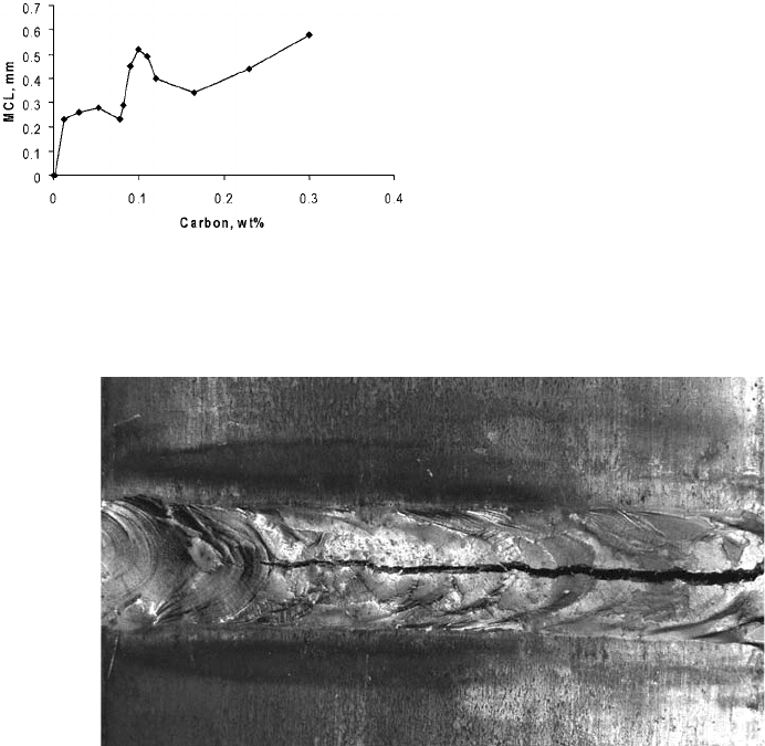
In the most recent work by Shankar and
Devletian (Ref 53, 54), the effect of carbon on
solidification cracking was nonlinear, with a
peak in cracking susceptibility at 0.1% C, as
shown in Fig. 18. In this study, testing was
performed on high-purity iron-carbon alloy
castings using the varestraint and transvar-
estraint tests. Maximum crack distance and
maximum crack length were measured at a 4%
augmented strain.
Fig. 18
Maximum crack length (MCL) as a function of carbon
content in iron weld metal obtained in transvar-
estraint tests at 4% augmented strain. Source: Ref 53, 54
Fig. 19 Solidification cracking in weld metal
516 / Failure Analysis of Heat Treated Steel Components
Name ///sr-nova/Dclabs_wip/Failure_Analysis/5113_503-519.pdf/Chap_14/ 18/8/2008 4:06PM Plate # 0 pg 516
The data (schematically plotted in Fig. 18)
clarify some of the conflicting issues in the
literature. Solidification cracking susceptibility
is controlled by the brittle temperature range
(BTR), the d?c transformation stress, and the
iron-carbon peritectic reaction. According to
Shankar and Devletian (Ref 53, 54), there are
four distinct %C ranges that produced char-
acteristic solidification behavior. These include:
Region 1: less than ~0.09% C (maximum
solid solubility of carbon in d-iron)
Region 2: ~0.09 to 0.11% C (maximum
solidification cracking)
Region 3: ~0.11 to 0.16% C
Region 4: greater than 0.16% C (iron-carbon
peritectic point)
In region 1, there was no cracking below
0.01% C in transvarestraint tests. This is because
the solidus/liquidus temperature range was
negligible. However, as the carbon content in-
creased, the cracking susceptibility increased
rapidly up to approximately 0.06% C. The
cracking dropped slightly at 0.075% and then
continued to increase with carbon content up to
0.09%, due to the increasing solidus/liquidus
temperature range. In region 2, a large peak in
solidification cracking was observed. This cri-
tical cracking peak, centered at approximately
0.1% C, was found to be due to the simultaneous
action of three factors: the maximum solidus/
liquidus temperature range, the d?c trans-
formation stresses, and the occurrence of the
BTR. At 0.1% C, cracking occurred with a
minimum critical strain and low fracture stress.
In region 3, solidification cracking decreased
with increasing carbon content because of the
decreasing solidus/liquidus temperature range.
In region 4, the solidification cracking suscept-
ibility increased due to the increasing solidus/
liquidus temperature range.
Example 10: Solidification Cracking of
Steel Weld. Welds were deposited by flux-
cored arc welding on 12 mm thick AISI/SAE
1020 steel plate at high travel speeds for maxi-
mum cost-effectiveness. Weld joints were
highly restrained during welding to prevent
distortion. Visible longitudinal centerline cracks
were observed, as shown in Fig. 19. The portions
of the weld seam that were not visibly cracked
failed the root bend test.
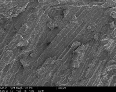
The cracked specimen was broken open and
observed under the SEM. Rejected bend-test
specimens were also broken open for examina-
tion by SEM. The crack surface clearly showed
that the mode of fracture was solidification
cracking, as shown in Fig. 20. Spectrographic
analysis of the weld metal admixture revealed a
carbon content of 0.1%. Subsequent welds were
deposited with reduced welding travel speed in
order to reduce the length of the teardrop shape
of the weld puddle. Subsequent welds deposited
at the reduced welding speed were crack-free.
Centerline cracking failure was caused by
solidification cracking. Decreasing welding
speed reduced susceptibility to solidification
cracking in the weld metal. Reducing restraint
during welding and reducing the weld metal
carbon content (or Matsuda’s L
t
factor, men-
tioned previously) would have also decreased
the occurrence of solidification cracking.
REFERENCES
1. AASHTO/AWS D1.5 Bridge Welding
Code, American Welding Society
2. N. Yurioka, M. Okumura, T. Kasuya, and
S. Ohshita, Welding Note, 3rd ed., Nippon
Steel, Japan, 1985
3. N. Yurioka, Weldability of Modern High
Strength Steels, Nippon Steel Corporation,
Japan, 1990
4. K. Shinada, Y. Horrii, and N. Yurioka,
Development of Weld Metal with High
Toughness and Low Har denability, Nippon
Steel Corporation, 1989
5. J.M. Sawhill, J.C. Baker, and P. Howe,
Hydrogen-Assisted Cracking in High
Strength Pipeline Steels, Weld. J., Vol 65
(No. 7), 1986, p 175s–183s
Fig. 20
Scanning electron micrograph of fracture surface
showing solidification cracking
Failure Analysis of Steel Welds / 517
Name ///sr-nova/Dclabs_wip/Failure_Analysis/5113_503-519.pdf/Chap_14/ 18/8/2008 4:06PM Plate # 0 pg 517
6. N. Yurioka and T. Kasuya, A Chart Method
to Determine Necessary Preheat in Welding,
Weld. World, Vol 35 (No. 5), 1995, p 31–38
7. N. Yurioka and T. Kasuya, “A Chart
Method to Determine Necessary Preheat in
Welding,” IIW Doc. II-1230-94 and IIW
Doc. IX-1740-94, International Institute of
Welding, 1994, p 12
8. T. Kasuya and N. Yurioka, Determination
of Necessary Preheat Temperature to Avoid
Cold Cracking under Varying Ambient
Temperature, ISIJ Int., Vol 35 (No. 10),
1995, p 1183–1189
9. M. McParlan and B.A. Graville, Hydrogen
Cracking in Weld Metals, Weld. J., Vol 55
(No. 4), 1976, p 95s–102s
10. J. Brozda, A Comparison Between the
Levels of Preheat Necessary to Prevent
Cold Cracking during Welding of Low
Alloy High Strength Steels, Weld. Int.,
Vol 11 (No. 2), 1997, p 25–32
11. B.A. Graville, “Interpretive Report on
Weldability Tests for Hydrogen Cracking of
Higher Strength Steels and their Potential
for Standardization,” Bulletin 400, Welding
Research Council, New York, 1995
12. T. Terasaki, G.T. Hall, and P.L. Harrison,
Predictive Equation for Cooling Time of
CTS Test Welds, Trans. Jpn. Weld. Soc.,
Vol 21 (No. 2), Oct 1990, p 51–55
13. N. Yurioka, H. Suzuki, H. Okumura, S.
Ohshita, and S. Saito, “Carbon Equivalents
to Assess Cold Cracking Sensitivity and
Hardness of Steel Welds,” Nippon Steel
Technical Report 20, Dec 1982, p 61–73
14. F.R. Coe, Welding Steels without Hydrogen
Cracking, The Welding Institute, Abington,
U.K., 1973
15. N. Yurioka, H. Suzuki, S. Ohshita and
S. Saito, Determination of Necessary Pre-
heat Temperature in Steel Welding, Weld.
J., Vol 62 (No. 6), 1983, p 147s–153s
16. C.L.M. Cottrell, An Improved Predictive
Method for Avoiding Hydrogen Cracking,
Weld. Met. Fabr., April 1990, p 178–183
17. N. Yurioka, “Studies on Delayed Cracking
in Steel Welds (Report 1); Prevention
of Root Cracking in Root-Pass Welds,”
Nippon Steel Corporation, Dec 1981
18. N. Yurioka, “Studies on Delayed Cracking
in Steel Welds (Report 2); Prevention of
Cracking in Restraint Multi-Run Welds,”
Nippon Steel Corporation, Dec 1981
19. N. Yurioka, “Studies on Delayed Cracking
in Steel Welds (Report 3); Prevention of
Micro- and Transverse Cracking in Weld
Metals,” Nippon Steel Corporation, Oct
1983
20. R.J. Wong and R.D. Hayes, Arc Welding
Consumables for HSLA Steels with Yield
Strengths of 80 ksi and Above, The Metal-
lurgy of Welding and Qualification of
Microalloyed Steel Weldments, J.T. Hickey
et al., Ed., American Welding Society,
1990, p 450–489
21. P.W. Holsberg and R.J. Wong, Welding of
HSLA-100 Steel for Naval Applications,
Weldability of Materials, R.A. Patterson
and K.W. Mohin, Ed., ASM International,
1990, p 219–239
22. J.J. DeLoach, C. Null, S. Fiore, and
P. Konkol, The Right Welding Wire Could
Help the U.S. Navy Save Millions, Weld. J.,
Vol 78 (No. 6), June 1999, p 55–58
23. R.A. Oriani and P.H. Josephic, Equilibrium
Aspects of Hydrogen-Induced Cracking of
Steels, Acta Metall., Vol 22 (No. 9), 1974,
p 1065–1074
24. R.A. Oriani, Effects of Hydrogen on the
Plastic Response of Steels, Hydrogen
Effects in Metals, I.M. Bernstein and A.W.
Thompson, Ed., Metallurgical Society of
AIME, 1981, p 235–245
25. R.A. Oriani, Hardening and Softening
Induced by Hydrogen in Carbon Steels,
NATO Conf. Series, Mater. Sci., Vol 5,
1983, p 795–798
26. J.K. Lin and R.A. Oriani, Effect of Hydro-
gen on the Initiation of Shear Localization
in Plain Carbon Steels, Perspectives in
Hydrogen in Metals, Pergamon Press, 1986,
p 615–621
27. R.A. Oriani, Hydrogen—The Versatile
Embrittler, Corrosion, Vol 43 (No. 7), July
1987, p 390–397
28. R.A. Oriani, Effects of Hydrogen on the
Plastic Properties of Medium Carbon Steels,
Metall. Trans. A, Vol 11 (No. 11), 1980,
p 1809–1820
29. J.K. Lin and R.A. Oriani, Effect of Hydro-
gen on the Initiation of Shear Localization
in Plain Carbon Steels, Acta Metall., Vol 31
(No. 7), 1983, p 1071–1077
30. H.A. Wriedt and R.A. Oriani, Effect of
Tensile and Compressive Elastic Stress
on Equilibrium Hydrogen Solubility in a
Solid, Acta Metall., Vol 18 (No. 7), 1970,
p 753–760
31. A.R. Troiano, The Role of Hydrogen
and Other Interstitials in the Mechanical
518 / Failure Analysis of Heat Treated Steel Components
Name ///sr-nova/Dclabs_wip/Failure_Analysis/5113_503-519.pdf/Chap_14/ 18/8/2008 4:06PM Plate # 0 pg 518