Bichop R.H. (Ed.) Mechatronic Systems, Sensors, and Actuators: Fundamentals and Modeling
Подождите немного. Документ загружается.

21-42 Mechatronic Systems, Sensors, and Actuators
stator coils supplied with a three-phase current. The rotational speed of the field is related to the frequency
of the currents.
(21.26)
where N
s
is the speed of the field in revolutions per minute and f is the frequency of the supply currents.
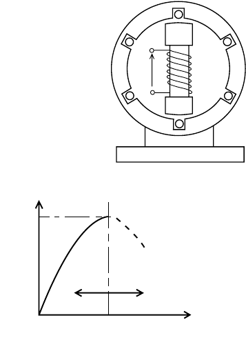
The mechanical construction is shown in Figure 21.70. The rotor field is supplied from a DC source
and the stator coils are supplied with a three-phase current. The rotating magnetic field is induced by
the stator coils and the rotor, which may be likened to a permanent bar magnet, aligns itself to the
rotating flux produced in the stator. When a mechanical load is driven by the shaft, the field produced
by the rotor is pulled out of alignment with that produced by the stator. The angle of misalignment is
called the “load angle.” The characteristics of synchronous motors are normally presented in terms of
torque against load angle, as shown in Figure 21.71.
The torque characteristic is basically sinusoidal with
(21.27)
where T
max
is the maximum rated torque and
δ
is the load angle.
It is evident from Equation 21.27 that synchronous motors have no starting torque and the rotor
must be run up to synchronous speed by some alternative means. One method utilizes a series of short-
circuited copper bars inserted through the outer extremities of the salient poles. The rotating magnetic
flux induces currents in these “grids” and the machine accelerates as if it were a cage-type induction
motor, see following section. A second method uses a wound rotor similar to a slip-ring induction motor.
The machine is run up to speed as an induction motor and is then pulled into synchronism to operate
as a synchronous motor.
The advantages of the synchronous motor are the ease with which the power factor can be controlled
and the constant rotational speed of the machine, irrespective of the applied load. Synchronous motors,
FIGURE 21.70 Simple synchronous motor.
FIGURE 21.71 Torque characteristic for a synchronous motor.
VDC
Y
0
Y
1
R
0
R
1
B
0
B
1
Torque
Working
region
Unstable
region
T
MAX
Load angle ( )
δ
N
s
60f
number of pole pairs
--------------------------------------------------=
TT
max
δ
sin=
9258_C021_Sect002-005.fm Page 42 Wednesday, October 10, 2007 7:10 PM
Actuators 21-43
however, are generally more expensive and a DC supply is a necessary feature of the rotor excitation.
These disadvantages coupled with the requirement for an independent starting mode make synchronous
motors much less common than induction motors.
21.2.9.2 Induction Motors
The stator of an induction motor is much like that of an alternator and in the case of a machine supplied
with three-phase currents, a rotating magnetic flux is produced. The rotor may be either of two basic
configurations, which are the “squirrel cage” or the slip-ring type. In the squirrel cage motor the rotor
core is laminated and the conductors consist of uninsulated copper, or aluminium, bars driven through
the rotor slots. The bars are brazed or welded at each end to rings or plates to produce a completely
short-circuited set of conductors. The slip-ring machine has a laminated core and a conventional three-
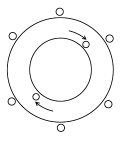
phase winding, similar to the stator, and connected to three slip-rings on the locating shaft. Figure 21.72
shows a schematic representation of an induction motor having three stator coils displaced by 120°.
If the stator coils are supplied with three-phase currents, a rotating magnetic field is produced in the
stator. Consider the single rotor coil shown in the figure. At standstill the rotating field will induce a
voltage in the rotor coil since there is a rate of change of flux linking the coil. If the coil forms a closed
circuit, the induced emf will circulate a current in the coil. The resultant force on the current carrying
conductor is a consequence of Equation 21.17 and this will produce a torque, which will accelerate the
rotor. The rotor speed will increase until the electromagnetic torque is balanced by the mechanical load
torque. The induction motor will never attain synchronous speed because if it did there would be no
relative motion between the rotor coils and the rotating field. Under these circumstances there would be
no emf induced in the rotor coils and subsequently no electromagnetic torque. Induction motors,
therefore, always run at something less than synchronous speed. The ratio of the difference between the
synchronous speed and the rotor speed to the synchronous speed is called the “slip”; i.e.,
(21.28)
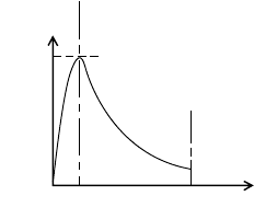
The torque–slip characteristic is shown in Figure 21.73. With the rotor speed equal to the synchronous
speed, i.e., s = 0, the torque is zero. As the rotor falls below the synchronous speed the torque increases
almost linearly to a maximum value dictated by the total of the load torque and that required to overcome
the rotor losses. The value of slip at full load varies between 0.02 and 0.06. The induction motor may
be regarded as a constant speed machine. The difficulties, in fact, of varying the speed constitute one of
the induction motor’s main disadvantages.
On start-up, the slip is equal to unity and the starting torque is sufficiently large enough to accelerate
the rotor. As the rotor runs up to its full load speed the torque increases in essentially inverse proportion
to the slip. The start-up and running curves merge at the full load position.
FIGURE 21.72 Schematic representation of an induc-
tion motor.
+
–
Y
0
R
1
B
0
Y
1
R
0
B
1
Rotor
s
N
s
N–
N
s
----------------=
9258_C021_Sect002-005.fm Page 43 Wednesday, October 10, 2007 7:10 PM
21-44 Mechatronic Systems, Sensors, and Actuators
21.2.9.3 Starting Induction Motors
As with DC motors, the current drawn during starting of AC motors is very large, up to about five times
full load current. A number of devices are therefore employed to limit the starting current but they all
involve the use of auxiliary equipment, which is usually quite expensive.
Star-Delta Starter
With the machine at standstill and the starter in the “start” position, the stator coils are connected in the
star pattern. As the machine accelerates up to running speed, the switch is quickly moved over to the “run”
position, which reconnects the stator windings in the delta pattern. By this simple expedient, the starting
supply current is reduced to about one third of what it would have been had the stator windings been
connected up in the delta pattern on start-up.
Autotransformer Starter
The autotransformer represents an alternative method of reducing the starting current drawn by an
induction motor. The autotransformer incorporates a star connection, which is supplied from a mid-point
tapping on each phase. The voltage supplied to the stator is, therefore, one half of the supply voltage. With
such an arrangement the supply current and the starting torque are both only one quarter of the values,
which would be applied to the motor when the full voltage is supplied. After the motor has accelerated,
the starter device is moved to the “run” position thereby connecting the motor directly across the supply
and opening the star-connection of the autotransformer. Unfortunately, the starting torque is also reduced
and the device is generally expensive since it has to have the same rating as the motor.
Rotor Resistance
With slip-ring induction motors, it is possible to include additional resistance in series with the rotor
circuit. The inclusion of extra resistance in the rotor provides for reduced starting current and improved
starting torque.
21.2.9.4 Braking Induction Motors
Induction motors may be brought to a standstill by either “plugging” or by “dynamic braking.”
1. Plugging: This is a technique where the direction of the rotating magnetic field is reversed. This
is brought about by reversing any two of the supply leads to the stator. The current drawn during
plugging is very large, and machines which are regularly plugged must be specially rated.
2. Dynamic braking: In this braking method the stator is disconnected from the AC supply and
reconnected to a DC source. The direct current in the stator produces a stationary unidirectional
field and as the rotor will always tend to align itself with the field, it will therefore come to a
standstill.
21.2.9.5 Speed Control of Induction Motors
Under normal circumstances, the running speed of an induction motor will be about 94–98% of the
synchronous speed, depending on the load. With the synchronous speed given by Equation 21.26, it is
clear that the speed may be varied either by changing the frequency of the supply current, or by changing
the number of poles.
FIGURE 21.73 Torque–slip characteristic for an induc-
tion motor.
Torque
Full-load torque
0 0.02-
0.06
Slip
9258_C021_Sect002-005.fm Page 44 Wednesday, October 10, 2007 7:10 PM
Actuators 21-45
Change of Supply Current Frequency
Solid state variable-frequency drives first began to appear in 1968. They were originally applied to the
control of synchronous AC motors in the synthetic fiber industry and rapidly gained acceptance in that
particular market. In more recent times they have been used in applications to pumping, synchronized
press lines, conveyor lines, and to a lesser extent in the machine-tool industry as spindle drives. Modern
AC variable-frequency motors are available in power ratings ranging from 1 to 750 kW and with speed
ranges from 10/1 to 100/1.
The synchronous and squirrel cage induction motors are the types most commonly used in conjunction
with solid-state, adjustable frequency inverter systems. In operation the motor runs at, or near, the
synchronous speed determined by the input current frequency. The torque available at low speed,
however, is decreased and the motor may have to be somewhat oversized to ensure adequate performance
at the lower speeds. The most advanced systems incorporate a digital tachogenerator to supply a corrective
feedback signal which is compared against a reference frequency. This gives a speed regulation of about
3%. Consequently, the AC variable-frequency drive is generally used only for moderate to high power
velocity control applications, where a wide range of speed is not required. The comparative simplicity
of the AC induction motor is usually sacrificed to the complexity and cost of the control electronics.
Change of Number of Poles
By bringing out the ends of the stator coils to a specially designed switch it becomes possible to change
an induction motor from one pole configuration to another. To obtain three different pole numbers, and
hence three different speeds, a fairly complex switching device would be required.
Changing the number of poles gives a discrete change in motor speed with little variation in speed
over the switched range. For many applications, however, two discrete speeds are all that is required and
changing the number of poles is a simple and effective method af achieving this.
Changing the Rotor Resistance
For slip-ring induction motors additional resistance can be coupled in series with the rotor circuit. It
has already been stated that this is a common enough method used to limit the starting current of such
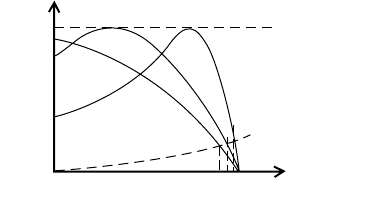
machines. It can also be used as a method of marginal speed control. Figure 21.74 shows the torque
characteristics of a slip-ring induction motor for a range of different resistances connected in series with
the rotor windings.
As the external resistance is increased from R
1
to R
3
, a corresponding reduction in speed is achieved
at any particular torque. The range of speeds is increased at the higher torques.
The method is simple and therefore inexpensive, but the reduction in speed is accompanied with a
reduction in overall efficiency. Additionally, with a large resistance in the rotor circuit, i.e., R
3
, the speed
changes considerably with variations in torque.
Reduced Stator Voltage
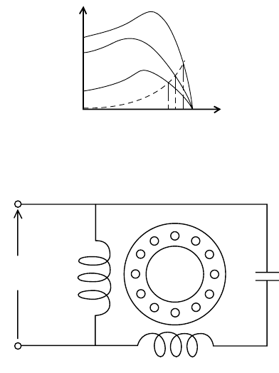
By reducing the applied stator voltage a family of torque–speed characteristics are obtained, as shown in
Figure 21.75.
It is evident that as the stator voltage is reduced from V
1
to V
3
, a change in speed is effected
FIGURE 21.74 Torque–speed characteristics for various rotor resistances.
Torque
Maximum, or
breakdown torque
Load torque
Speed
R
3
N
3
N
2
N
1
R
2
R
1
9258_C021_Sect002-005.fm Page 45 Wednesday, October 10, 2007 7:10 PM
21-46 Mechatronic Systems, Sensors, and Actuators
at any particular value of torque. This is provided, of course, that the torque does not exceed the maximum
load torque available at the reduced stator voltage. This latter point is obviously a limiting factor, which
places a constraint on this method of speed control. Generally only very small speed ranges can be
obtained using variable stator supply voltage.
21.2.9.6 Single-Phase Induction Motors
The operation of an induction motor depends upon the creation of a rotating magnetic field. A single
stator coil cannot achieve this and all of the so-called single-phase induction motors use some or other
external means of generating an approximation to a two-phase stator supply. Two stator coils are,
therefore, used and these are displaced by 90°. Ideally the currents which supply each coil should have
a phase difference of 90°. This then gives the two-phase equivalent of the three-phase induction motor.
The Shaded Pole Motor
The stator of the shaded pole motor consists of a salient pole single-phase winding and the rotor is of
the squirrel cage type. One half of the stator features a copper “shading ring.” When the exciting coil is
supplied with alternating current, the flux produced induces a current in the shading ring. The phase
difference between the currents in the exciting coil and the shading ring is relatively small and the rotating
field produced is far from ideal. In consequence the shaded pole motor has a poor performance and an
equally poor efficiency due to the continuous losses in the shading rings. Shaded pole motors have a low
starting torque and are used only in light duty applications such as small fans and blowers or other easily
started equipment. Their advantage lies in their simplicity and low cost of manufacture.
The Capacitor Motor
The stator has two windings physically displaced by 90°. A capacitor is connected in series with the
auxiliary winding such that the currents in the two windings have a large phase displacement (see
Figure 21.76). The current phase displacement can be made to approach the ideal 90°, and the perfor-
mance of the capacitor motor closely resembles that of the three-phase induction motor.
FIGURE 21.75 Torque–speed characteristics for various stator voltages.
FIGURE 21.76 Capacitor motor.
Torque
Load torque
Speed
N
3
N
2
N
1
V
1
V
2
V
1
AC
supply
Main
winding
Auxiliary winding
9258_C021_Sect002-005.fm Page 46 Wednesday, October 10, 2007 7:10 PM
Actuators 21-47
The Universal Motor
These are small DC series-wound motors that operate at about the same speed and power on direct
current, or on single-phase current with approximately the same root mean square voltage. If alternating
current is supplied, the stator and rotor field strengths vary sinusoidally in magnitude but with the same
phase relationship. As the applied voltage changes polarity, so do the armature and field currents.
Equation 21.25 suggests that under these conditions the applied torque will not reverse polarity and will
remain at all times positive. The universal, or plain-series motor, is used mainly in small domestic
appliances such as hair dryers, electric drills, vacuum cleaners, hedge trimmers, etc.
21.2.9.7 The DC Permanent Magnet (PM) Motor
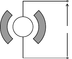
The DC permanent magnet (PM) motor is a continuous rotation electromagnetic actuator that can be
directly coupled to its load. Figure 21.77 shows the schematic representation of a PM motor. The PM
motor consists of an annular brush ring assembly, a permanent magnet stator ring, and a laminated wound
rotor. They are particularly suitable for servo systems where size, weight, power, and response times must
be minimized and where high position and rate accuracies are required.
The response times for PM motors are very fast and the torque increases directly with the input current,
independently of the speed or the angular position. Multiple pole machines maximize the output torque
per watt of rotor power. Commercial PM motors are available in many sizes from 35 mN m at about 25 mm
diameter to 13.5 N m at about 3 m diameter.
Direct drive rate and position systems using PM motors utilize DC tachogenerators and position
sensors in various forms of closed-loop feedback paths for control purposes.
21.2.9.8 The Stepper Motor
A stepper motor is a device that converts a DC voltage pulse train into a proportional mechanical rotation
of its shaft. In essence, stepper motors are a discrete version of the synchronous motor. The discrete
motion of the stepper motor makes it ideally suited for use with a digitally based control system such as
a microcontroller. The speed of a stepper motor may be varied by altering the rate of the pulse train
input. Thus, if a stepper motor requires 48 pulses to rotate through one complete revolution, then an
input signal of 96 pulses per second will cause the motor to rotate at 120 rev/min. The rotation is actually
carried out in finite increments of time; however, this is visually indiscernible at all but the lowest speeds.
Stepper motors are capable of driving a 2.2-kW load with stepping rates from 1000 to 20,000 per
second in angular increments from 180° down to 0.75°.
There are three basic types of stepper motor, viz.
1. Variable reluctance: This type of stepper motor has a soft iron multi-toothed rotor with a wound
stator. The number of teeth on the rotor and stator, together with the winding configuration and
excitation determines the step angle. This type of stepper motor provides small to medium sized
step angles and is capable of operation at high stepping rates.
2. Permanent magnet: The rotor used in the PM type stepper motor consists of a circular permanent
magnet mounted onto the shaft. PM stepper motors give a large step angle ranging from 45° to
120°.
FIGURE 21.77 A DC permanent magnet motor.
V
DC
9258_C021_Sect002-005.fm Page 47 Wednesday, October 10, 2007 7:10 PM
21-48 Mechatronic Systems, Sensors, and Actuators
3. Hybrid: The hybrid stepper motor is a combination of the previous two types. Typically the stator
has eight salient poles, which are energized by a two-phase winding. The rotor consists of a
cylindrical magnet, which is axially magnetized. The step angle depends on the method of con-
struction and is generally in the range 0.9°–5°. The most popular step angle is 1.8°.
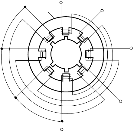
The principle of operation of a stepper motor can be illustrated with reference to a variable reluctance,
four-phase machine. This motor usually has eight stator teeth and six rotor teeth, see Figure 21.78.
If phase 1 of the stator is activated alone, two diametrically opposite rotor teeth align themselves with
the phase 1 teeth of the stator. The next adjacent set of rotor teeth in the clockwise direction are then
15° out of step with those of the stator. Activation of the phase 2 winding on its own, would cause the
rotor to rotate a further 15° in the anti-clockwise direction to align the adjacent pair of diametrically
opposite rotor teeth. If the stator windings are excited in the sequence 1, 2, 3, 4, then the rotor will move
in consecutive 15° steps in the anti-clockwise direction. Reversing the excitation sequence will cause a
clockwise rotation of the rotor.
21.2.9.9 Stepper Motor Terminology
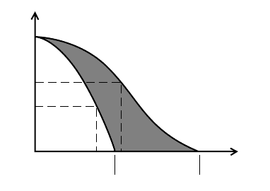
Pull-out torque: The maximum torque that can be applied to a motor, running at a given stepping
rate, without losing synchronism.
Pull-in torque: The maximum torque against which a motor will start, at a given pulse rate, and reach
synchronism without losing a step.
Dynamic torque: The torque developed by the motor at very slow stepping speeds.
Holding torque: The maximum torque that can be applied to an energized stationary motor without
causing spindle rotation.
Pull-out rate: The maximum switching rate at which a motor will remain in synchronism while the
switching rate is gradually increased.
Pull-in rate: The maximum switching rate at which a loaded motor can start without losing steps.
Slew range: The range of switching rates between pull-in and pull-out in which a motor will run in
synchronism but cannot start or reverse.
The general characteristics of a typical stepper motor are given in Figure 21.79.
FIGURE 21.78 Variable reluctance stepper motor.
Stator
Rotor
1
2
3
4
9258_C021_Sect002-005.fm Page 48 Wednesday, October 10, 2007 7:10 PM
Actuators 21-49
During the application of each sequential pulse, the rotor of a stepper motor accelerates rapidly towards
the new step position. However, on reaching the new position there will be some overshoot and oscillation
unless sufficient retarding torque is provided to prevent this happening. These oscillations can cause rotor
resonance at certain pulse frequencies resulting in loss of torque, or perhaps even pull-out conditions. As
variable reluctance motors have very little inherent damping, they are more susceptible to resonances than
either of the permanent magnet, or the hybrid types. Mechanical and electronic dampers are available,
which can be used to minimize the adverse effects of rotor resonance. If at all possible, the motor should
be selected such that its resonant frequencies are not critical to the application under consideration.
Owing to their unique characteristics, stepper motors are widely used in applications involving posi-
tioning, speed control, timing, and synchronized actuation. They are prevalent in X-Y plotters, floppy
disc head drives, printer carriage drives, numerically controlled machine tool slide drives, automatic teller
machines, and camera iris control mechanisms.
By far the most severe limitation on the purely electric stepper motor is its power handling capability.
Currently this is restricted to about 2.25 kW.
21.2.9.10 Brushless DC Motors
These motors have position feedback of some kind so that the input waveforms can be kept in the proper
timing with respect to the rotor position. Solid-state switching devices are used to control the input signals
and the brushless DC motor can be operated at much higher speeds with full torque available at those
speeds. The brushless motor can normally be rapidly accelerated from zero to operating speed as a PM
motor. On reaching operating speed, the motor can then be switched over to synchronous operation.
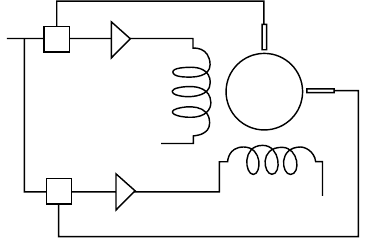
The brushless motor system consists of a wound stator, a permanent magnet rotor, a rotor position
sensor, and a solid state switching assembly. The wound stator can be made with two or more input
phases. Figure 21.80 gives the schematic representation of a two-phase brushless motor.
The torque output of phase A is
(21.29)
where
Ι
Α
= current in phase A,
K
T
= (ZΦ/2
π
) = torque constant of the motor,
p = number of poles, and
θ
= angular position of the rotor.
In the expression for the torque constant, Z is the total number of conductors, and Φ is the magnetic flux.
FIGURE 21.79 Stepper motor characteristics.
Curve A - Pull-out torque
Curve B - Pull-in torque
A
B
Torque
Pull-out
torque
Pull-in
torque
Pull-in
rate
Pull-out
rate
Maxpull-in rate Maxpull-out rate
Speed
TI
A
ZΦ/2
π
()p
θ
/2()sin I
A
K
T
p
θ
/2()sin==
9258_C021_Sect002-005.fm Page 49 Wednesday, October 10, 2007 7:10 PM
21-50 Mechatronic Systems, Sensors, and Actuators
In a similar manner, the torque output of phase B is
(21.30)
If the motor currents are arranged to be supplied in the following relationships
then the total torque for a two-pole motor becomes
(21.31)
Equation 21.31 shows that if all of the above conditions are satisfied then the brushless DC motor
operates in a similar manner to the conventional DC motor, i.e., the torque is directly proportional to
the armature current. Note that the armature current in this context refers to the stator windings.
Excitation of the phases may be implemented with sinusoidal, or square wave inputs. The sine wave drive
is the most efficient but the output transistors in the drive electronics must be capable of dissipating
more power than that dissipated in square wave operation. Square wave drive offers the added advantage
that the drive electronics can be digitally based. The brushless DC motor will duplicate the performance
characteristics of a conventional DC motor only if it is properly commutated. Proper commutation
involves exciting the stator windings in a sequence that keeps the magnetic field produced by the stator
approximately 90 electrical degrees ahead of the rotor field. The brushless DC motor therefore relies
heavily on the position feedback system for effective commutation. It might also be apparent that the
brushless motor as described is not strictly a DC machine, but a form of AC machine with position
feedback.
21.2.10 Motor Selection
For the mechatronics engineer the main concerns regarding electric motors will be those of selection for
purpose. At the very least the motor must be capable of matching the power requirements of the driven
load. In all cases, therefore, the motor power available should be enough to cope with the anticipated
demands of the load. Other requirements are the need for the motor to have enough torque available
on start-up to overcome the static friction, accelerate the load up to the working speed, and be able to
handle the maximum overload. Too much excess motor torque on start-up might result in a violent
initial acceleration. Some systems therefore require a “soft start” whereby the motor torque is gradually
increased to allow the load to accelerate gently.
FIGURE 21.80 Two-phase brushless motor.
Input
Rotor
Sensor A
Sensor B
Controllers
Power
amplifiers
A
φ
φ
TI
B
K
T
p
θ
/2()sin=
I
A
Ip
θ
/2()and I
B
Ip
θ
/2()cos=sin=
TT
A
T
B
+ IK
T
p
θ
/2()
2
p
θ
/2()
2
cos+sin[]IK
T
===
9258_C021_Sect002-005.fm Page 50 Wednesday, October 10, 2007 7:10 PM
Actuators 21-51
The operating speed of the motor will be fixed by the point at which the torque supplied by the motor
is just balanced by the torque requirements of the load. At any other condition, the motor and load will
be either accelerating or decelerating. Correct matching of a motor to a driven machine can only be
confidently accomplished if both the motor and the load torque–speed characteristics are known. The
motor torque–speed characteristics are usually provided by the supplier. The driven machine torque–speed
characteristics can be something of an enigma.
Friction devices like industrial sanders, buffers, and polishing machines have a torque–speed charac-
teristic that is initially very high, but drops sharply once motion is established. Continued acceleration
usually sees the torque requirement of the load decrease further but at a slower rate than that at start-
up. The difference between the static and dynamic friction accounts for this behavior.
Fans and blowers have a torque–speed characteristic that increases parabolically from zero as the speed
increases. Such machines do not, therefore, need much motor torque to enable them to start.
High inertia devices like machine tool drives, rolling mills, and electric lifts require a large torque on
start-up to overcome the inertia. Once motion is established the torque requirements tend to decrease
with increasing speed. The series-wound DC motors are ideal for these types of loads.
This brief discussion of rotating electrical machines is in no way comprehensive. A fuller discourse on
AC and DC machines is given both by Gray [1] and Sen [2]. Orthwein [3] presents an interesting practical
discussion on the mechanical applications of AC and DC motors and Kenjo and Nagamori [4] provide
a detailed in-depth study of permanent-magnet DC motors.
References
1. Gray, C. B. (1989), Electrical Machines and Drive Systems, Longmans Scientific and Technical, Harlow.
2. Sen, P. C. (1989), Principles of Electric Machines and Power Electronics, Wiley, Chichester.
3. Orthwein, W. (1990), Machine Component Design, West Publishing, St Paul, Minnesota.
4. Kenjo, T. & Nagamori, S. (1985), Permanent Magnet and Brushless dc Motors, Monographs in Electrical
& Electronic Engineering, Clarendon Press, Oxford.
21.3 Piezoelectric Actuators
Habil Ramutis Bansevicius and Rymantas Tadas Tolocka
21.3.1 Piezoeffect Phenomenon
The piezoelectric effect was discovered by the Curie brothers in 1880 [1]. The direct piezoelectric effect
contains the ability of certain materials, which are called piezomaterials, to generate electric charge in
proportion to externally applied force. The effect is reversible and then is called an inverse piezoelectric
effect. The effects have been used for actuating/sensing functions in engineering applications.
21.3.2 Constitutive Equations
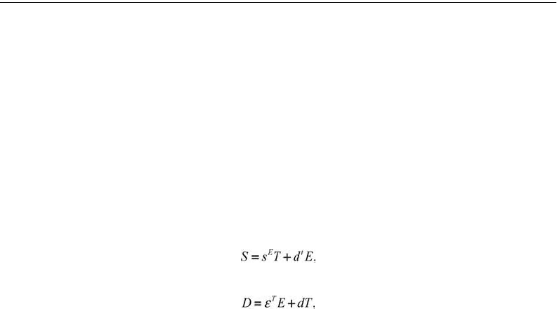
Coupled electric and mechanical constitutive equations of piezoelectric materials for one-dimension
medium are:
(21.31)
(21.32)
9258_C021_Sect002-005.fm Page 51 Wednesday, October 10, 2007 7:10 PM
