Bichop R.H. (Ed.) Mechatronic Systems, Sensors, and Actuators: Fundamentals and Modeling
Подождите немного. Документ загружается.

21-32 Mechatronic Systems, Sensors, and Actuators
storage elements, where the energy is stored in the induced magnetic field. The voltage across an ideal
inductor V
I
(t) is
(21.15)
where i
I
(t) is the current going through the inductor and L is the inductance. When the current to the
inductor is suddenly switched off, e.g., by switching off a driving transistor, Equation 21.15 indicates
that there will be a large transient voltage build-up across the inductor. If not properly suppressed this
transient voltage can shorten or even damage the driving transistor. This is sometimes called inductor
kickback.
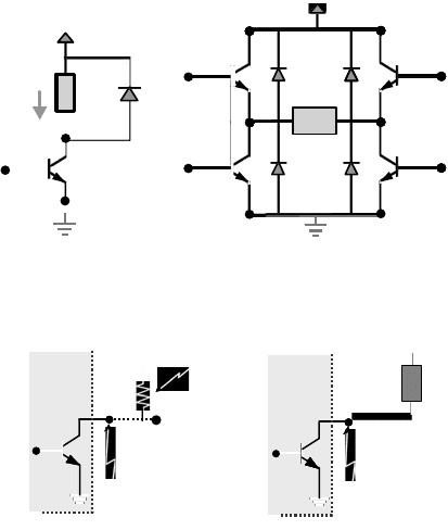
A simple method of reducing the instantaneous switching voltage surge is to create a loop for the
excess energy to flow. This can be done by placing diodes in parallel with the load, see Figure 21.54.
Figure 21.54 illustrates two methods of using flyback or free-wheeling diodes to suppress switching voltage
surge when driving inductive loads.
Open-Collector Output
For some digital devices, the output stage (pin) is simply the collector of a transistor. This is called an
open-collector output, see Figure 21.55. Since the output of the device is only the collector of a transistor,
it has no output drive capacity. The output value can be measured through a pull-up resistor, see
Figure 21.55. Open-collector output is convenient for driving electromechanical devices if the output
transistor can sink adequate current, see Figure 21.57.
Isolation
Recall that the power amplification/modulation part of an electromechanical actuator contains both low-
and high-energy signals, see Figure 21.2. For safety and reliability reasons, it is desired to prevent transients
or noise spikes in the high power side of the system from the signal processing (low power) side of the
circuit. Mechanical relay is one option. Optoisolators or optocouplers use light to couple the high and low
FIGURE 21.54 Using diodes to reduce swithcing voltage when driving inductive loads.
FIGURE 21.55 Open-collector output.
Loa d
+V
+V
i
I
Loa d
load
Q4
Q1 Q2
Q3
Load
R
P
5V
Open
Collector
Output
Open
Collector
Output
Digital
Device
Pull-up
Resistor
Load
V
CC
Digital
Device
V
I
t() L
d
dt
-----
i
I
t()⋅=
9258_C021_Sect001.fm Page 32 Wednesday, October 10, 2007 7:09 PM

Actuators 21-33
energy side of the device. Typically, an LED source is combined with either a phototransistor or photo
thyristor, see Figure 21.35. In addition to signal isolation, optoisolators also help to reduce ground loop
issues between the logic and power side of the circuit.
Grounding
It is important to provide common ground among the different devices. For electromechanical actuators,
the high energy side is often switching at high frequency; if the ground point of the high energy side of
the circuit is directly connected to the ground of the low energy side of the circuit, switching noise may
propagate through the ground wire and negatively affect the operation of the low energy side of the
system. It is recommended that separate common grounds are established for the high and low energy
side and the two grounds are then connected at the power supply. In addition, an adequate-sized ground
plane needs to be provided to minimize the possibility of differences among grounding points.
21.2 Electrical Machines
Charles J. Fraser
The utilization of electric motors as the power source in a mechatronic application is substantial. Electric
motors, therefore, often feature as the prime mover in a variety of driven systems. It is usually the
mechanical features of the application that determines the type of electric motor to be employed. The
torque–speed characteristics of the motor and the driven system are therefore very important. It is perhaps
then a paradox that while the torque–speed characteristics of the motor are readily available from the
supplier, the torque–speed characteristics of the driven system are often quite obscure.
21.2.1 DC Motor
All conventional electric motors consist of a stationary element and a rotating element, which are separated
by an air gap. In DC motors, the stationary element consists of salient “poles,” which are constructed of
laminated assemblies with coils wound round them to produce a magnetic field. The function of the
laminations is to reduce the losses incurred by eddy currents. The rotating element is traditionally called
the “armature” and this consists of a series of coils located between slots around the periphery of the
armature. The armature is also fabricated in laminations, which are usually keyed onto a location shaft.
A very simple form of DC motor is illustrated in Figure 21.56.
The single coil is located between the opposite poles of a simple magnet. When the coil is aligned in
the vertical plane, the conventional flow of electrons is from the positive terminal to the negative terminal.
The supply is through the brushes, which make contact with the commutator segments. From Faraday’s
laws of electromagnetic induction, the “left-hand rule,” the upper part of the coil will experience a force
acting from right to left. The lower section will be subject to a force in the opposite direction. Since the
FIGURE 21.56 Single-coil, 2-pole DC motor.
Magnet
N
+ve
–ve
Brush
Commutator
S
Coil
9258_C021_Sect002-005.fm Page 33 Wednesday, October 10, 2007 7:10 PM
21-34 Mechatronic Systems, Sensors, and Actuators
coil is constrained to rotate, these forces will generate a torque, which will tend to make the coil turn in
the anti-clockwise direction. The function of the commutator is to ensure that the flow of electrons is
always in the correct direction as each side of the coil passes the respective poles of the magnet. The
commutator incorporates brass segments, separated by insulating mica strips. The carbon brushes make
sliding contact with the commutator.
When the coil lies in the horizontal direction, there is maximum magnetic flux linking the coil but a
minimum rate of change of flux linkages. On the other hand, when the coil is in the vertical plane, there
is zero flux linking the coil but the rate of change of flux linkages is a maximum. The resultant change
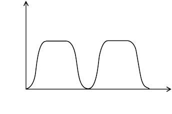
in torque acting on the coil through one revolution is as shown in Figure 21.57.
If two coils physically displaced by 90° are used in conjunction with two separate magnets, also
displaced by 90°, then the output torque is virtually constant. With the introduction of a second coil,
the commutator needs to have four separate segments. In a typical DC machine there may be as many
as 36 coils, which would require a 72-segment commutator.
The simple DC motor of Figure 21.56 can be improved in perhaps three obvious ways. Firstly, the
number of coils can be increased, the number of turns in each coil can be increased, and finally the
number of magnetic poles can be increased. A typical DC machine would therefore normally incorporate
four poles, wired in such a way that each consecutive pole has the opposite magnetic polarity to each of
its immediate neighboring poles. If the torque generated in the armature coils are to assist one another
then while one side of the coil is passing under a north pole, the other side must be passing under a
south pole. With a two-pole machine the armature coils are wound with one side of the coil diametrically
opposite the other. In a four-pole machine the coils are wound such that one side of the coil is displaced
90° from the other. The size of the machine will generally determine how many coils and the number
of turns on each coil which can be accommodated.
21.2.2 Armature Electromotive Force (emf)
If a conductor cuts a magnetic flux, a voltage of 1 V will be induced in the conductor if the flux is cut
at the rate of 1 Wb/s. Denoting the flux per pole as Φ and the speed (in rev/s), as N, for a single turn
coil and two-pole machine, the emf induced in the coil is given as
(21.15)
For a machine having Z
s
armature conductors connected in series, i.e., Z
s
/2 turns, and 2p magnetic
poles, the total induced emf is
(21.16)
FIGURE 21.57 Torque variation through one revolution.
T
orque
0 180 360
An
g
le of rotation [de
g
rees]
E
coil
flux per pole
time for half rev
--------------------------------------
Φ
1/2N
------------
2NΦ===
E
2NΦZ
s
2p
2
------------------------ 2NΦZ
s
p==
9258_C021_Sect002-005.fm Page 34 Wednesday, October 10, 2007 7:10 PM
Actuators 21-35
The induced emf or back emf will oppose the applied voltage. Since the emf is directly proportional
to the motor speed then on startup, there will be no back emf generated. This will have consequences
on the current, which will be drawn by the coils, and some measures will have to be taken to counteract
this effect. This topic will be considered later.
21.2.3 Armature Torque
The force on a current carrying conductor is given as
(21.17)
where B is the magnetic flux density under a pole, I is the current flowing in the conductor, and L is the
axial length of the conductor.
The torque on one armature conductor is, therefore,
(21.18)
where r is the radius of the armature conductor about the center of rotation, I
a
is the current flowing in
the armature conductor, L is the axial length of the conductor, and B
av
is the average flux density under
a pole.
Given that the resultant torque per conductor is
(21.19)
For Z
s
armature conductors connected in series, the total torque (in Nm) on the armature is given by
(21.20)
21.2.4 Terminal Voltage
Denoting the terminal voltage by V, in normal running conditions we have a balanced electrical system
where:
(21.21)
Since the number of poles and number of armature conductors are fixed, then from Equation 21.16
we have a proportionality relationship between the speed, the induced emf, and the magnetic flux, i.e.,
(21.22)
Using Equation 21.21
(21.23)
Since the value of I
a
R
a
is normally less than about 5% of the terminal voltage then to a reasonable
approximation
(21.24)
FBLI=
TFrB
av
LI
a
r==
B
av
Φ/(2
π
rL)/2p[],=
T
Φ2pLI
a
r
2
π
rL
---------------------
ΦpI
a
π
------------
==
T
ΦpI
a
Z
s
π
-----------------
=
VEI
a
R
a
+=
N
E
Φ
----
∝
N
VI
a
R
a
–()
Φ
------------------------
∝
N
V
Φ
----
∝
9258_C021_Sect002-005.fm Page 35 Wednesday, October 10, 2007 7:10 PM
21-36 Mechatronic Systems, Sensors, and Actuators
Similarly Equation 21.19 provides a proportionality relationship between the torque, the armature
current, and the magnetic flux, i.e.,
(21.25)
Equation 21.24 shows that the speed of the motor is directly proportional to the applied voltage and
inversely proportional to the magnetic flux. All methods of speed control for DC motors are based on
this proportionality relationship.
Equation 21.25 indicates that the torque of a given DC motor is directly proportional to the product
of the armature current and the flux per pole. It is obvious therefore that speed control methods which
are based on altering the magnetic flux will also have an effect on the output torque.
21.2.5 Methods of Connection
21.2.5.1 The Shunt-Wound Motor
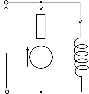
The shunt-wound motor (Figure 21.58) is wired such that the armature and field coils are connected in
parallel with the supply.
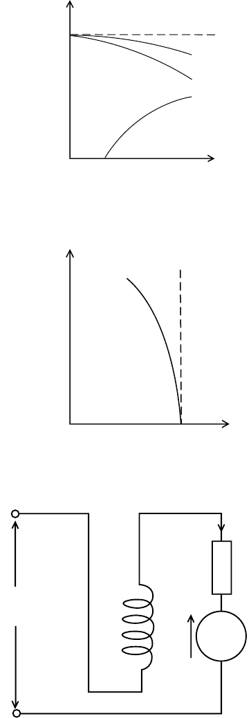
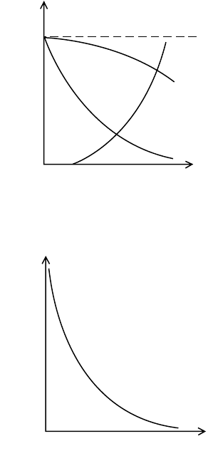
Under normal operating conditions, the field current will be constant. As the armature current
increases, the armature reaction effect will weaken the field and the speed will tend to increase. However,
the induced voltage will decrease due to the increasing armature voltage drop and this will tend to decrease
the speed. The two effects are not self cancelling and overall the motor speed will fall slightly as the
armature current increases.
The motor torque increases approximately linearly with the armature current until the armature
reaction starts to weaken the field. These general characteristics are shown in Figure 21.59 where it can
also be seen that no torque is developed until the armature current is large enough to overcome the
constant losses in the machine. Figure 21.60 shows the derived torque-speed characteristic.
Since the torque increases dramatically for a slight decrease in speed, the shunt-wound motor is partic-
ularly suitable for driving equipment like pumps, compressors, and machine tool elements where the
speed must remain “constant” over a wide range of load conditions.
21.2.5.2 The Series-Wound Motor
The series-wound motor is shown in Figure 21.61. As the load current increases, the induced voltage,
E
,
will decrease due to the armature and field resistance drops. Because the field winding is connected in series
with the armature, the flux is directly proportional to the armature current. Equation 21.24 therefore
FIGURE 21.58 The shunt-wound motor.
TI
a
Φ∝
Supply
V
E
M
R
a
I
a
I
f
9258_C021_Sect002-005.fm Page 36 Wednesday, October 10, 2007 7:10 PM
Actuators 21-37
suggests that the speed–armature current characteristic will take the form of a hyperbola. Similarly,
Equation 21.25 indicates that the torque–armature current characteristic will be approximately parabolic.
These general characteristics are illustrated in Figure 21.62, along with the derived torque–speed charac-
teristic in Figure 21.63. The general characteristics indicate that if the load falls to a particularly low value
FIGURE 21.59 The shunt-wound motor load characteristics.
FIGURE 21.60 The shunt-wound torque–speed characteristics.
FIGURE 21.61 The series-wound motor.
Applied voltage, V
Speed
E
Torque
Armature current
Speed
EMF
Torque
Speed
Torque
Supply
V
E M
I
a
R
a
9258_C021_Sect002-005.fm Page 37 Wednesday, October 10, 2007 7:10 PM
21-38 Mechatronic Systems, Sensors, and Actuators
then the speed may become dangerously high. A series-wound motor should never be used, therefore, in
situations where the load is likely to be suddenly relaxed.
The main advantage of the series-wound motor is that it provides a large torque at low speeds. Series-
wound motors are eminently suitable, therefore, for applications where a large starting torque is required.
This includes, for example, lifts, hoists, cranes, and electric trains.
21.2.5.3 The Compound-Wound Motor
Compound-wound motors are produced by including both series and shunt fields. The resulting char-
acteristics of the compound-wound motor fall somewhere in between those of the series-wound and the
shunt-wound machines.
21.2.6 Starting DC Motors
With the armature stationary, the induced emf is zero. If while at rest, the full voltage is applied across the
armature winding then the current drawn would be massive. A typical 40-kW motor might have an armature
resistance of about 0.06 Ω. If the applied voltage is 240 V, the current drawn is 4000 A. This current would
undoubtedly blow the fuses and thereby cut off the supply to the machine. To limit the starting current a
variable external resistance is connected in series with the armature. On start-up the full resistance is
connected in series. As the machine builds up speed and increases the back emf, the external resistance can
be reduced until at rated speed the series resistance is disconnected. Alternatively, a series resistance can
be momentarily activated in conjunction with the starter switch.
FIGURE 21.62 The series-wound motor load characteristics.
FIGURE 21.63 The series-wound motor torque–speed characteristics.
Applied voltage, V
Torque
Speed
EMF
Torque
Arm
atu
r
e
cu
rr
e
n
t
Speed
E
Torque
S
p
eed
9258_C021_Sect002-005.fm Page 38 Wednesday, October 10, 2007 7:10 PM
Actuators 21-39
21.2.7 Speed Control of DC Motors
Equation 21.24 shows that the speed of a DC motor is influenced both by the applied voltage and the
magnetic flux. A change in either one of these parameters will therefore effect a change in the motor
speed.
21.2.7.1 Field Regulator
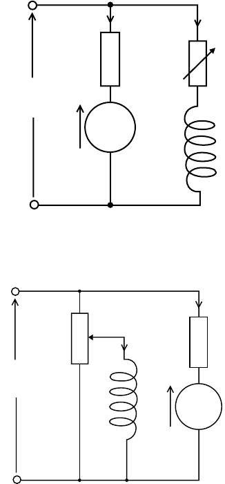
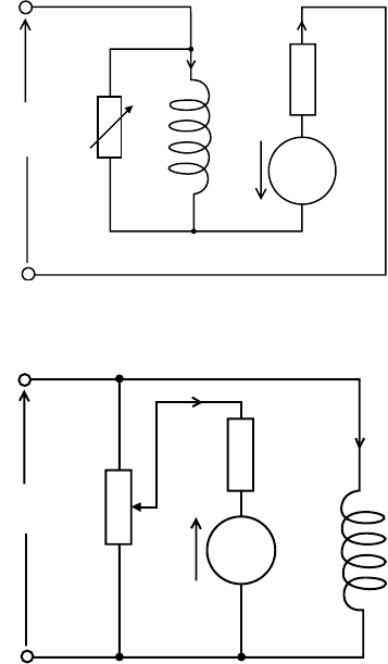
For shunt-wound and compound-wound motors a variable resistor, called a “field regulator,” can be
incorporated in series with the field winding to reduce the flux. For the series-wound motor the variable
resistor is connected in parallel with the field winding and is called a “diverter.” Figures 21.64–21.66 show
the various methods of weakening the field flux for shunt-, compound-, and series-wound motors.
In all of the above methods, the flux can only be reduced and from Equation 21.24 this implies that
the speed can only be increased above the rated speed. The speed may in fact be increased to about three
or four times the rated speed. The increased speed, however, is at the expense of reduced torque since
the torque is directly proportional to the flux which is being reduced.
21.2.7.2 Variable Armature Voltage
Alternatively, the speed can be increased from standstill to rated speed by varying the armature voltage
from zero to rated value. Figure 21.67 illustrates one method of achieving this.
FIGURE 21.64 Speed control by flux reduction: shunt-wound motor.
FIGURE 21.65 Speed control by flux reduction: compound-wound motor.
Supply
V
E
M
R
a
I
a
I
f
Supply
V
E M
R
a
I
a
I
f
9258_C021_Sect002-005.fm Page 39 Wednesday, October 10, 2007 7:10 PM
21-40 Mechatronic Systems, Sensors, and Actuators
The potential divider carries the same current as the motor, and this limits this method of speed
control to small machines. Additionally much of the input energy is dissipated in the variable resistance,
which consequently renders the system inefficient.
21.2.7.3 Ward Leonard Drive
In this case the variable DC voltage for the speed controlled motor is obtained from a separate DC
generator, which is in itself driven by an induction motor.
The field coil for the DC generator is supplied from a center-zero potential divider. When the wiper
arm is in the center position, the speed controlled motor is at a standstill. By moving the wiper arm away
from the center position the speed of the motor is increased in either clockwise or anti-clockwise direction.
The Ward Leonard drive is smooth and accurate in either direction and also provides for very responsive
braking. The complexity, however, makes it a very expensive system, and it is only used in high quality
applications.
21.2.7.4 Chopper Control
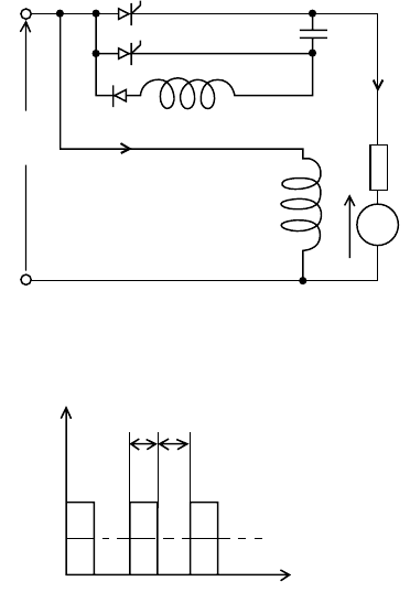
Figure 21.68 shows a thyristor circuit connected in series with the armature of a DC motor. The thyristor
circuit is triggered such that it operates essentially as a high speed ON/OFF switch. The output waveform
across the armature terminals is depicted in Figure 21.69. The ratio of time on to time off, i.e., the
“mark/space ratio,” can be varied with the result that the average voltage supplied to the armature is
effectively varied between zero and fully on. The frequency of the signal may be up to about 3 kHz and
the timing circuit is quite complex. Speed control of DC motors using thyristors, however, is effective
and relatively inexpensive.
FIGURE 21.66 Speed control by flux reduction: series-wound motor.
FIGURE 21.67 Speed control by varying the armature voltage.
Supply
V
E M
R
a
I
a
I
f
Supply
V
E
M
R
a
I
a
I
a
9258_C021_Sect002-005.fm Page 40 Wednesday, October 10, 2007 7:10 PM
Actuators 21-41
21.2.8 Efficiency of DC Machines
The losses in DC machines can be generally classified as
1. Armature losses:This is the I
2
R loss in the armature winding, often referred to as the “copper loss.”
2. Iron loss: This loss is attributable to magnetic hysteresis and eddy currents in the armature and
field cores.
3. Commutator losses: This loss is related to the contact resistance between the commutator brushes
and segments. The total commutator loss is due to both mechanical friction and a voltage loss
across the brushes.
4. Excitation loss: In shunt-wound machines, this power loss is due to the product of the shunt
current and the terminal voltage.
5. Bearing friction and windage: Bearing friction is approximately proportional to the speed, but
windage loss varies with the cube of the speed. Both of these losses are fairly minor unless the
machine is fitted with a cooling fan, in which case the windage loss can be quite significant.
Despite the variety and nature of the losses associated with DC machines, they have nonetheless a very
good performance with overall efficiencies, often in excess of 90%.
21.2.9 AC Machines
21.2.9.1 Synchronous Motors
Synchronous motors are so called because they operate at only one speed, i.e., the speed of a rotating
magnetic field. The production of the rotating magnetic field may be actioned using three, 120° displaced,
FIGURE 21.68 Speed control using thyristors.
FIGURE 21.69 Voltage across armature terminals.
Supply
V
M
R
a
V
a
I
a
I
f
V
a
Mark
Space
Average value of V
a
Time
9258_C021_Sect002-005.fm Page 41 Wednesday, October 10, 2007 7:10 PM
