Bichop R.H. (Ed.) Mechatronic Systems, Sensors, and Actuators: Fundamentals and Modeling
Подождите немного. Документ загружается.

21-2 Mechatronic Systems, Sensors, and Actuators
with the load or physical environment. In addition, we will look at the electronic components that are
essential for modulating the necessary electrical energy.
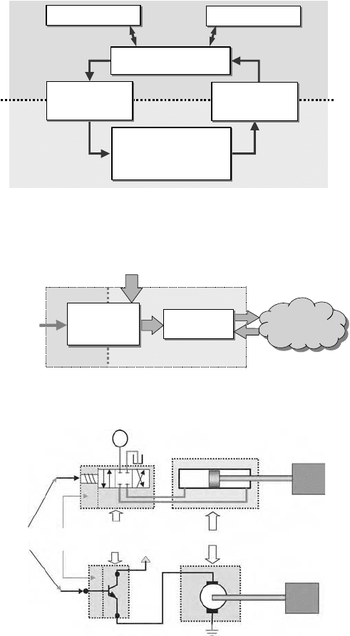
From an energy perspective, a mechatronic system can be separated into a relatively higher energy
(power) portion that interacts with the physical world and a relatively low energy (power) portion that
process the data, see Figure 21.1. Sensor and actuators are the interfacing devices that accomplish the
tasks of energy modulation and energy conversion. Therefore, an actuator can be viewed as having the
structure depicted in Figure 21.2. Typically, actuators are considered only as energy conversion devices.
However, with the proliferation of power electronics, we will take a more inclusive view of actuators that
also includes power amplification. An electrohydraulic linear actuator, see Figure 21.3, can also be similarly
classified, where the spool valve is the power amplification/modulation block with spool position as the
FIGURE 21.1 Mechatronic system.
FIGURE 21.2 Actuator functional diagram.
FIGURE 21.3 Electrohydraulic and electromechanical actuators.
Communication Operator interface
High power
Low power
Physical process
mixture of mechanical, fluid,
thermal, chemical, electrical
components/subsystems
Information processing
electronics, software
Actuators
power modulation,
energy conversion
Sensors
energy conversion,
signal processing
Control
signal
Load
environment
Actuator
Low power
High power
Unmodulated
energy source
Power
amplification
& modulation
Energy
conversion
LOAD
LOAD
+V
Energy conversion
Power
amplification
& modulation
Low
energy
Control
signal
Ps
9258_C021_Sect001.fm Page 2 Wednesday, October 10, 2007 7:09 PM
Actuators 21-3
control signal and the hydraulic pressure/flow is the energy source. The hydraulic cylinder acts as the
energy conversion device that converts fluidic energy to mechanical energy. For a typical electromechanical
actuator, such as a DC motor (Figure 21.3), the power amplification block is the motor driver that
amplifies signal level (low current/power) control signal to the higher power (large current) signal that
is used to convert electrical energy to mechanical energy through the electromagnetic principle.
In this chapter, we will first present an overview of common types of electromechanical actuators.
They will be classified by the respective energy conversion mechanism. The power electronic components,
such as diodes, thyristors, and transistors, which are used for power amplification and modulation, will
be presented followed by discussion of common power amplification building blocks. We will conclude
by discussing some issues related to interfacing with electromechanical actuators.
21.1.2 Type of Electromechanical Actuators—Operating Principles
Converting electrical energy to mechanical energy is the common thread among different electrome-
chanical actuators. Physics provided us with many different mechanisms either through direct conversion
such as piezoelectric or through an intermediate medium such as a magnetic field. We will present an
overview of the more common electromechanical actuators by their energy conversion mechanism:
electromagnetic, electrostatic, and piezoelectric. The following discussion is intended to provide intro-
ductory information about the types of electromechanical actuation and is by no means exhaustive.
Detailed discussion of each can be found in subsequent chapters, where they will be discussed in more
detail.
21.1.2.1 Electromagnetics—Magnetic Field
Electromagnetic is the most widely utilized method of energy conversion for electromechanical actuators.
One of the reasons for using magnetic fields instead of electric fields is the higher energy density in magnetic
fields. The air gap that separates a stationary member (stator) and a moving member of an electrome-
chanical actuator is where the electromechanical energy conversion takes place. The amount of energy
per unit volume of air gap for magnetic fields can be five orders of magnitude higher than that of electric
fields.
Lorentz’s law of electromagnetic forces and Faraday’s law of electromagnetic induction are the two
fundamental principles that govern electromagnetic actuators. Before going into the detail of electro-
magnetics, we will first introduce the concept of magnetic field and flux.
Magnetic flux
φ
exists due the presence of a magnetic field. The magnetic field strength (in A/m)
and the magnetic flux density (in tesla [T]) are related by the permeability of the material. In a vacuum,
the magnetic flux density is directly proportional to the magnetic field strength and is expressed by
(21.1)
where
µ
0
= 4[T m/A] is the permeability constant. For other magnetic or ferromagnetic materials the
relationship is given by
(21.2)
where
µ
r
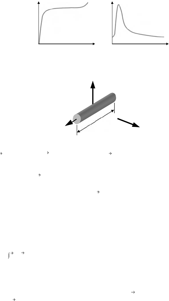
() is the relative permeability of the material. Figure 21.4 shows typical B-H and
µ
-H curves.
Lorentz’s Law of Electromagnetic Force
When a current carrying conductor is placed in a magnetic field, it will be subjected to an induced force
given by
(21.3)
H
B
B
µ
0
H
⋅=
B
µ
r
H()
µ
⋅
0
H⋅=
H
F
i
B
×=
9258_C021_Sect001.fm Page 3 Wednesday, October 10, 2007 7:09 PM
21-4 Mechatronic Systems, Sensors, and Actuators
where is the force vector, is the current vector, and is the magnetic flux density. The force is called
the electromagnetic force or the Lorentz force. If a conductor of length L carrying constant current i is
placed in a constant (independent of location) field B, as shown in Figure 21.5, the magnitude of the
resultant Lorentz force exerted by the field B on the conductor is
(21.4)
Faraday’s Law of Electromagnetic Induction
The motion of a conductor in a magnetic field will produce an electromotive force (emf), or electric
potential, across the conductor given by
(21.5)
where
φ
=
°
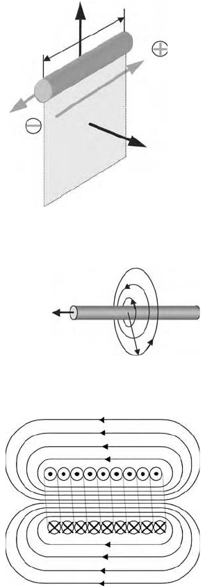
is the magnetic flux. For a conductor of length L moving at a constant speed v in a
constant (independent of location) magnetic field that is perpendicular to the area A, as shown in
Figure 21.6, the magnitude of the induced electromotive force (electric potential) is
(21.6)
There are two methods to generate a desired magnetic field , or equivalently, a desired magnetic
flux density . One is to use a permanent magnet and the other is to utilize the Boit–Savart law.
Boit–Savart Law
A long (infinite), straight, current carrying conductor induces a magnetic field around the conductor, see
Figure 21.7. The flux density at a perpendicular distance r from the conductor is
(21.7)
FIGURE 21.4
µ
-H diagram and B-H diagram.
FIGURE 21.5 Lorentz’s electromagnetic force.
H H
B
µ
L
Electromagnetic
(Lorentz) force
F
→
Electric
current
i
→
Flux
denity
B
→
F
i
B
F
F |
F
| BLi==
emf E −
d
φ
dt
------
==
B
d
A
⋅
emf EBLv==
H
B
B
µ
r
µ
0
2
π
r
----------
i⋅=
9258_C021_Sect001.fm Page 4 Wednesday, October 10, 2007 7:09 PM
Actuators 21-5
where i is the electric current. If we bend the straight current carrying conductor into a helical coil
(solenoid) with N turns, it will induce a corresponding magnetic field as depicted in Figure 21.8. If the
length of the coil L is much greater than its diameter D, the flux density follows the right-hand rule and
the magnitude inside the coil is approximately
(21.8)
where
µ
=
µ
r
·
µ
0
is the permeability of the material inside the coil and i is the current through the
winding. This field can be intensified by inserting a ferromagnetic core into the solenoid by increasing
the permeability. Coil induced magnetic fields is widely utilized in electromagnetic devices for generating
controlled magnetic fields and are often referred to as electromagnets.
FIGURE 21.6 Motion induced electromotive force.
FIGURE 21.7 Magnetic field generated by current carrying conductor.
FIGURE 21.8 Coil (solenoid) induced magnetic field.
A
Electromotive
force (emf)
Velocity
V
→
Flux
denity
B
→
i
→
r
Electric
current
i
→
B
→
B
µ
N
L
----
i⋅=
9258_C021_Sect001.fm Page 5 Wednesday, October 10, 2007 7:09 PM
21-6 Mechatronic Systems, Sensors, and Actuators
Solenoid Type Devices
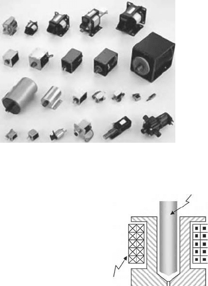
Solenoids, see Figure 21.9, is the simplest electromagnetic actuators that are used in linear as well as
rotary actuations for valves, switches, and relays. As the name indicates, a solenoid consists of a stationary
iron frame (stator), a coil (solenoid), and a ferromagnetic plunger (armature) in the center of the coil,
see Figure 21.10.
As the coil is energized, a magnetic field is induced inside the coil. The movable plunger moves to
increase the flux linkage by closing the air gap between the plunger and the stationary frame. The magnetic
force generated is approximately proportional to the square of the applied current i and is inverse
proportional to the square of the air gap
δ
, which is the stroke of the solenoid, i.e.,
(21.9)
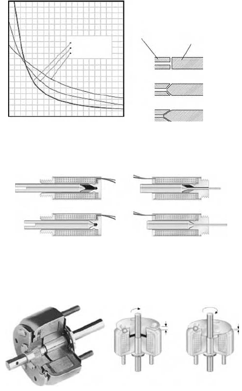
As shown in Figure 21.11, for strokes less than 0.060 in., the flat face plunger is recommended with a
pull or push force three to five times greater than 60° plungers. For longer strokes up to 0.750 in., the
60° plunger offers the greatest advantage over the flat face plunger. When the coil is de-energized, the
field decreases and the plunger will return to the original location either by the load itself or through a
return spring.
All linear solenoids basically pull the plunger into the coil when energized. Push-type solenoids are
implemented by extending the plunger through a hole in the back-stop, see Figure 21.12. Therefore, when
energized, the plunger is still pulled into the coil, but the extended producing a pushing motion from
the back end of the solenoid. Return motion, upon de-energizing the coil, is provided by the load itself
(i.e., the weight of the load) and/or by a return spring, which can be provided as an integral part of the
solenoid assembly.
FIGURE 21.9 Assorts of solenoid actuators. (Courtesy of Shih Hsing Industrial Co., Ltd.)
FIGURE 21.10 A typical solenoid.
Plunger
Frame
Coil
F
i
2
δ
2
----
∝
9258_C021_Sect001.fm Page 6 Wednesday, October 10, 2007 7:09 PM
Actuators 21-7
Rotary solenoids utilize ball bearings that travel down inclined raceways to convert linear motion to
rotary motion. When the coil is energized, the plunger assembly is pulled towards the stator and rotated
through an arc determined by the coining of the raceways, see Figure 21.13. An electromechanical relay
(EMR) is a device that utilizes a solenoid to close or open a mechanical contact (switch) between high
power electrical leads. A relay performs the same function as a power transistor in that relatively small
electrical energy is used to switch a large amount of currents. The difference is that a relay has the
capability of controlling much larger current level. Variations on this mechanism are possible: some relays
have multiple contacts, some are encapsulated, some have built-in circuits that delay contact closure after
actuation, and some, as in early telephone circuits, advance through a series of positions step by step, as
they are energized and de-energized.
Design/Selection Considerations. Force, stroke, temperature, and duty cycle are the four major design/
selection considerations for solenoids. A linear solenoid can provide up to 30 lb of force from a unit
less than in. long. A rotary solenoid can provide well over 100 lb of torque from a unit also less than
in. long. As shown in Figure 21.11, the relationship between force and stroke can be modified by
changing the design of some internal components. Higher performance, e.g., force output, can be
FIGURE 21.11 Typical force-stroke curve of solenoids. (Courtesy of Magnetic Sensor Systems.)
FIGURE 21.12 Push and pull type solenoids. (Courtesy of Ledex® & Dormeyer® Products.)
FIGURE 21.13 Rotary solenoid. (Courtesy of Ledex® & Dormeyer® Products.)
Plunger
Back stop
Stroke
Conical 60°
Conical 60°
Conical 90°
Conical 90°
Flat
Flat
Force
De-energizedDe-energized
Energized
pull type
Energized
pull type
Energized
(CW rotation)
De-energized
2
1
/
4
2
1
/
4
9258_C021_Sect001.fm Page 7 Wednesday, October 10, 2007 7:09 PM
21-8 Mechatronic Systems, Sensors, and Actuators
achieved by increasing the current to the coil winding. However, higher current tends to increase the
winding temperature. As the winding temperature increases, the wire resistance increases. This will
reduce the output force level. Solenoids are often rated as operating under continuous duty cycle or
intermittent duty cycle. A solenoid rated for 100% duty cycle may be energized at its rated voltage
continuously because its total coil temperature will not exceed maximum allowable ratings, while an
intermittent duty cycle solenoid has an associated allowable “on” time which must not be exceeded.
Intermittent duty coils provide considerably higher forces than continuous duty solenoids. The maxi-
mum operating temperature for a solenoid is determined by the rated temperature of the insulation
material used in the winding (see Table 21.1).
Voice-Coil Motors (VCMs)
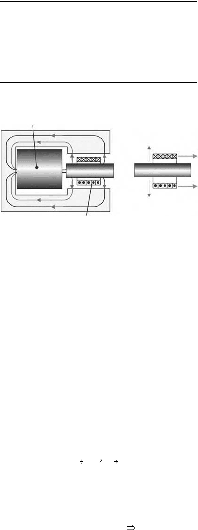
As the name indicates, the voice-coil motor was originally developed for loudspeakers. It is now exten-
sively used in moving read/write heads in hard disk drives. Since the coil is in motion, VCM is also
referred to as a moving-coil actuator. The VCM consists of a moving coil (armature) in a gap and a
permanent magnet (stator) that provides the magnetic field in the gap, see Figure 21.14. When current
flows through the coil, based on the Lorentz law, the coil experiences electromagnetic (Lorentz) force F
Since most voice-coils are designed so that the flux is perpendicular to the current direction, the resultant
Lorentz force can be written as
(21.10)
where l is the coil length per turn, B is the flux density, N is the number of turns in the coil, i is the
current, and
γ
is a coil utilization factor. It is important to know that the force is proportional to the
applied current amplitude and the proportional constant K
F
is often called the force constant.
TABLE 2 1. 1 Temprature Rating for Electrical Insulations
Insulation Classification Temperature Rating
Class A Class 105 105°C 221°F
Class E Class 120 120°C 248°F
Class B Class 130 130°C 266°F
Class F Class 155 155°C 311°F
Class H Class 180 180°C 356°F
Class N Class 200 200°C 392°F
FIGURE 21.14 Voice-coil motor.
Moving coil
NS
Iron
Iron
Magnetic flux
Lorentz
force
F
F
B
B
Permanent magnet
F
i
B
×=
F
VCM
γ
BNl i⋅ K
F
iF
VCM
i∝⋅==
9258_C021_Sect001.fm Page 8 Wednesday, October 10, 2007 7:09 PM
Actuators 21-9
The coil is usually suspended in the gap by springs and attached to the load such as the diaphragm
of an audio speaker, the spool of a hydraulic valve, or the read/write head of the disk drive. The linear
relationship between the output force and the applied current and the bidirectional capability makes the
voice coil more attractive than solenoids. However, since the controlled output of the voice coil is force,
some type of closed loop control or some type of spring suspension is needed.
Design/Selection Consideration. From Equation 21.10 we see that the force constant depends on the
flux density and the amount of wires that can be packed into the gap. There are two options to increase
the force constant. One is to increase the flux density, which can be achieved by using stronger magnetic
material and the other is to increase either N or l, i.e., to pack more turns and/or make a larger diameter
coil.
Given a fixed gap volume, using higher gauge (thinner) wires is the only way to increase the number
of turns. However, higher gauge wires have larger resistance, which will increase the resistive heating of
the winding and limit the allowable current. In addition, the additional insulation will also occupy more
volume and tends to reduce the effect of increasing N. In summary, to improve the performance of the
voice coil, a designer can either choose a better magnetic material or to make the motor bigger by either
making the coil wider (increase D) or longer (increase N).
Electric Motors
Electric motors are the most widely used electromechanical actuators. They can either be classified based
on functionality or electromagnetic characteristics. The differences in electric motors are mainly in the
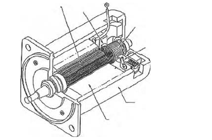
rotor design and the method of generating the magnetic field. Figure 21.15 shows the composition of a
permanent magnet DC motor. Some common terminologies for electric motors are:
Stator is the stationary outer or inner housing of the motor that supports the material that generates
the appropriate stator magnetic field. It can be made of permanent magnet or coil windings.
Field coil (system) is the portion of the stator that is responsible for generating the stator (field) magnetic
flux.
Rotor is the rotating part of the motor. Depending on the construction, it can be a permanent magnet
or a ferromagnetic core with coil windings (armature) to provide the appropriate armature field to
interact with the stator field to create the torque.
Armature is the rotor winding that carries current and induces a rotor magnetic field.
Air gap is the small gap between the rotor and the stator, where the two magnetic fields interact and
generate the output torque.
Brush is the part of a DC motor through which the current is supplied to the armature (rotor). For
synchronous AC motors, this is done by slip rings.
FIGURE 21.15 Permanent magnet DC motor. (From T. Keujo and S. Nagamori, Permanent-Magnet and Brushless
DC Motors, 1985, by permission of Oxford University Press.)
Commutator
Housing
Stator
(permanent magnent for filed
flux)
Brush
Brush
Rotor (armature)
9258_C021_Sect001.fm Page 9 Wednesday, October 10, 2007 7:09 PM

21-10 Mechatronic Systems, Sensors, and Actuators
Commutator is the part of the DC motor rotor that is in contact with the brushes and is used for
controlling the armature current direction. Commutation can be interpreted as the method to control
the current directions in the stator and/or the armature coils so that a desired relative stator and rotor
magnetic flux direction is maintained. For AC motors, commutation is done by the AC applied current
as well as the design of the winding geometry. For stepping motors and brushless DC (BLDC) motors,
commutations are done in the drive electronics and/or motor commands.
Torque generation in an electric motor is either through the interaction of the armature current
and the stator magnetic field (Lorentz Law) or through the interaction of the stator field and the
armature field. Table 21.2 summarizes the common classification of electric motors. The next chapter
will give a detailed discussion of the operation of various electric motors and the associated design
considerations.
TABLE 2 1. 2 Electric Motor Classification
Classification
Command
Input Magnetic Field Description
DC motors Permanent magnet Permanent magnets are used to generate the stator magnetic field
Electrical current is supplied directly into the armature winding of
the rotor through the brushes and commutators
Electro-
magnets
Shunt wound A stator (field) winding is used as electromagnet. Stator winding is
connected in parallel with the armature winding
Series wound A stator (field) winding is used as electromagnet. Stator winding is
connected in series with the armature winding
Compound wound Two stator (field) windings are used as electromagnet. The stator
windings are connected, one in series and one in parallel, with the
armature winding
Separate wound A stator (field) winding is used as electromagnet. Both the stator and
armature fields are individually energized
AC motors Single-phase Induction Single stator winding with squirrel-cage rotor. No external connection
to the rotor. Torque generation is based on the electromagnetic
induction between the stator and rotor. AC current provides the
commutation of the fields. Rotor speed is slightly slower than the
rotating stator field (slip)
Synchronous Permanent magnet rotor or rotor winding with slip ring commutation.
Rotating speed is synchronized with the frequency of the AC source
Poly-phase Induction Similar to single-phase induction motor but with multiple stator
windings. Self-starting
Synchronous Similar to single-phase synchronous motor but with multiple stator
windings for smoother operation
Universal Essentially a single-phase AC induction motor with similar electrical
connection as a series wound DC motor. Can be driven by either AC
or DC source
Stepper
Motors
Permanent magnet Permanent magnet rotor with stator windings to provide matching
magnetic field. By applying different sequence (polarity) of coil
current, the rotor PM field will align to match induced stator field
Variable reluctance Teethed ferromagnetic rotor with stator windings. Rotor motion is the
result of the minimization of the magnetic reluctance between the
rotor and stator poles
Hybrid Multi-toothed rotor with stator winding. The rotor consists of two
identical teethed ferromagnetic armatures sandwiching a permanent
magnetic
Brushless
DC
motors
Poly-phase Synchronous Essentially a poly-phased AC synchronous motor but using electronic
commutation to match rotor and stator magnetic fields. Electronic
commutation enables using a DC source to drive the synchronous
motor
9258_C021_Sect001.fm Page 10 Wednesday, October 10, 2007 7:09 PM
Actuators 21-11
21.1.2.2 Electrostatics—Electrical Field
Since electrical fields have lower energy density than magnetic fields, typical applications of electrical field
forces are limited to measurement devices and accelerating charge particles, where the required energy
density is small. Recently, with the proliferation of microfabrication technology, it is possible to apply
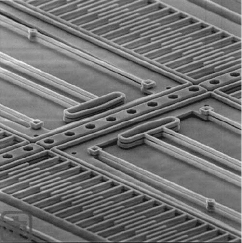
the small electrostatic forces to microelectromechanical actuators, such as comb actuators (see Figure
21.16). The advantage of electrostatic actuation is the higher switching rate and less energy loss as
compared to the electromagnetic actuation. However, the limitation in force, travel, and high operating
voltage still needs to be addressed. Electrostatic actuation is the main actuation for moving charged toner
particles in electrophotographic (xerographic) processes, e.g., laser printers.
21.1.2.3 Piezoelectric
Piezoelectric is the property of certain crystals that produces a voltage when subjected to mechanical
deformation, or undergoes mechanical deformation when subjected to a voltage. When a piezoelectric
material is under mechanical stress, it produces an asymmetric displacement in the crystal structure
and in the charge center of the affected crystal ions. The result is charge separation. An electric potential
proportional to the mechanical strain can be measured. This is called the direct piezoelectric effect.
Conversely, the material will have deformation without volume change when electric potential is
applied. This reciprocal piezoelectric effect can be used to produce mechanical actuation. There are two
categories of piezoelectric materials: sintered ceramics, such as lead-zirconate-titinate (PZT), and
polymers, such as polyvinylidence fluoride (PVDF). Piezoceramics have a larger force output and are
used more as actuators. PVDFs tend to generate larger deformation and are used more for sensor
applications.
FIGURE 21.16 MEMS comb actuator uses electrostatic actuation. (Courtesy of Sandia National Laboratories,
MEMS and Novel Si Science and Technology Department, SUMMIT Technologies, www.mems.sandia.com.)
9258_C021_Sect001.fm Page 11 Wednesday, October 10, 2007 7:09 PM
