Bichop R.H. (Ed.) Mechatronic Systems, Sensors, and Actuators: Fundamentals and Modeling
Подождите немного. Документ загружается.

21-62 Mechatronic Systems, Sensors, and Actuators
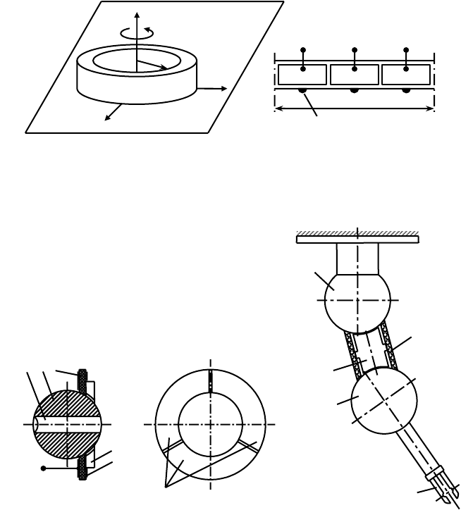
placed on the inner wall of the cylinder are sectioned as shown in its development. Activation of any of
the electrodes with alternating voltage of resonant frequency U
i
(t), i= 1,2,3 results in excitation of
oscillations in the piezoceramics, which generate the driving forces, acting in the corresponding direction
in the contact zone of the plate and contacting pads of the cylinder. Generation of axial traveling wave
oscillations of the cylinder by activation of all electrodes with a phase shift results in the rotation of the
cylinder around its axis.
A practical example is Robot’s eye (Figure 21.85a) in which miniature CCD camera 1 is fixed in the
passive sphere 2, contacting with piezoelectric ring 3 with sectioned electrodes (in this case into 3
symmetric parts). Constant pressure in the contact zone is developed by permanent magnet 4. The system
is a kinematic pair possessing a variable number of degrees of freedom. Activation of any of the electrodes
results in the rotation of the sphere around the axis, position of which can be controlled by changing
the activated electrode. Generation of travelling wave oscillations of the ring results in the rotation of
the sphere around the axis of the ring. Approximately 2 angular second resolutions in every direction
can be achieved higher than the requirements for robot vision systems.
FIGURE 21.84 Positioning system.
FIGURE 21.85
Peizoelectric devices with several degrees of freedom: (a) robot’s eye and (b) Peizoelectric robot.
z
ϕ
R
y
x
U
1(t)
2R
U
2(t)
U
3(t)
Contacting pad
π
(a) (b)
4
3
2
1
Gripper
N
S
123
U(t)
4
5
Electrodes
9258_C021_Sect002-005.fm Page 62 Wednesday, October 10, 2007 7:10 PM

Actuators 21-63
Another practical example is a piezoelectric robot (Figure 21.85b), consisting of two spheres 1 and 2,
made from passive material (e.g., steel), with a piezoelectric transducer 3 between them. The contact
forces are ensured with the help of permanent magnet 4. Consisting of two spherical joints (two kinematic
pairs) the robot has up to 6 degree of freedom. The structure control and motions (rotations) in all
directions are achieved in the same manner as in the previous examples. The same active link is being
used here in two kinematic pairs to increase redundancy in the system. Using direct piezoeffect it is
possible to extract additional information (with the help of additional electrodes on the active link) on
the forces and torque, acting on the gripper and on the state of contacting surfaces. This information is
used to reduce positioning errors and to correct the motion trajectory.
References
Cady, W.G., Piezoelectricity, Dover publications, New York, 1964.
Volkov, V., Some theoretical problems in modern techniques of diagnostics in mechanical systems, in
Proc. Int. AMSE Conf. Systems Analysis, Control and Design, Lyon, France, 1994, pp. 205–212.
Williams, W. and Brown, W.J., Piezoelectric Motor, US Patent 2,439,499, 1942.
Ragulskis, K. and Bansevitchyus, R., Vibromotors – high frequency vibration motion converters, in Proc.
Int. Symp. Exploitation of Vibration, East Kilbridge, Glasgow, 1974, pp. 1–16.
Ragulskis, K. and Bansevicius, R., Vibromotors, Mokslas, Vilnius, 1981, (in Russian).
Ragulskis, K., Bansevicius, R. Barauskas, and G. Kulvietis, Vibromotors for Precision Microrobots, Hemi-
sphere Publishing Corporation, 1988.
Sashida, T. and Kenjo, T., An Introduction to Ultrasonic Motors, Oxford Science Publications, 1993, Oxford
University Press, New York.
Ueha, S. and Tomikawa, Y., Ultrasonic Motors, Theory and Application, Oxford Science Publications,
Oxford Press, Oxford, 1993.
Uchino, K., Piezoelectric Actuators and Ultrasonic Motors, Kluwer Academic Publishers, MA, 1997.
21.4 Hydraulic and Pneumatic Actuation Systems
Massimo Sorli and Stefano Pastorelli
21.4.1 Introduction
The primary function of an actuation system is to influence the controlled system so as to obtain the
desired movement or action. This objective is made possible by the actuation system, which converts the
primary energy with which the actuator operates into the final mechanical energy.
There are three main types of power with which actuation systems work: electric power, hydraulic
power, and pneumatic power. The first envisages the use of electric actuators such as motors, solenoids,
and electromagnets. The remaining two envisage the use of cylinders (linear motors) and rotary motors,
substantially similar in form and dimensions, the motion of which is respectively governed by a fluid
considered uncompressible in an initial approximation (a hydraulic liquid, mineral oil generally, or a
liquid with lower viscosity) and by a compressible fluid (compressed air or a generic gas).
Other types of energy are available but are fairly unusual in automatic systems. Chemical energy and
thermal energy, which cause a change of phase in a material or the thermodynamic expansion of the
systems into a mechanical movement, can be considered in this category.
The characteristics of fluid servosystems are examined below, with particular reference to systems
which permit continuous control of one of the two physical magnitudes which express the fluid power:
pressure and flow rate. In general, pressure control is carried out in cases in which it is necessary to create
a determined force or torque law, while flow rate control is used to carry out controls on kinematic
magnitudes such as position, speed, and acceleration.
9258_C021_Sect002-005.fm Page 63 Wednesday, October 10, 2007 7:10 PM
21-64 Mechatronic Systems, Sensors, and Actuators
Continuous control of a force or of a speed can be effectively realized with a fluid actuation device,
with evident advantages compared with electric actuation, such as the possibility of maintaining the
system under load without any limitation and with the aid of adequate control devices, the possibility
of carrying out linear movements directly at high speeds, without devices for transforming rotary motion
to linear, and the possibility of having high bandwidths, in particular in hydraulic systems, as these have
limited dimensions and therefore low inertia.
21.4.2 Fluid Actuation Systems
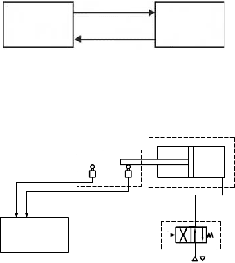
An actuation system, which is part of an automatic machine, consists of a power part and a control part
as illustrated in Figure 21.86. The power part comprises all the devices for effecting the movements or
actions. The control part provides for the processing of the information and generates the automated
cycle and the laws of variation of the reference signals, in accordance with the governing procedures
implemented and with the enabling and feedback signals arriving from the sensors deployed on the
operative part. The order signals coming from the control part are sent to the operative part by means
of the interface devices which convert and amplify the signals, where necessary, so that they can be used
directly by the actuators. These interfaces can be the speed drives or the contactors of the electric motors,
the distributor valves in hydraulic and pneumatic actuators.
Figure 21.87 illustrates a fluid actuation system. The power part consists of the actuator—a double-
acting cylinder in the case in the figure—the front and rear chambers of which are fed by a 4/2 distributor
valve, which constitutes the fluid power adjustment interface.
The valve switching command is the order from the control part. This order is sent in accordance with
the movement strategy, determined by the desired operating cycle of the cylinder in the control part, on
the basis of the feedback signals from the sensors in the cylinder, represented in the figure by the limit
switches.
Then there are discontinuous actuation systems and continuous actuation systems, depending on the
type of automation realized, while retaining the control part and the actuation part. The first are effective
when used in discontinuous automation, typical of assembly lines and lines for the alternating handling
of machine parts or components; on the other hand, continuous actuation systems are found in contin-
uous process plants and as continuous or analog control devices for the desired magnitudes, and con-
stitute fluid servosystems.
FIGURE 21.86 Actuation system.
FIGURE 21.87 Fluid power actuation system.
Power
Feedback
Orders
Part Part
Control
Sensors
Command
part
Orders
Actuator
Interface
Feedback
9258_C021_Sect002-005.fm Page 64 Wednesday, October 10, 2007 7:10 PM

Actuators 21-65
Fluid actuators, whether they are linear (cylinders) or rotary (motors) are continuous systems as they
can determine the positioning of the mobile component (of the rod with respect to the cylinder liner;
of the shaft with respect to the motor casing) at any point in the stroke. Performance of the usual cylinders
and motors is currently highly influenced by the action of friction (static and dynamic) developed by
contacts between mobile parts. This action, in pneumatic systems in particular, gives rise to the well-
known phenomenon of stick-slip, or intermittent motion at very low movement speeds, due to the
alternation of conditions of friction and adherence in the motion of the mobile element in the actuator.
Given the nature of the friction itself, the presence of devices suitable for sustaining the mobile compo-
nents of the actuator and maintaining the correct pressure conditions, such as supports and gaskets, gives
rise to nonlinear conditions in the equilibrium of the actuator, increasing the level of difficulty in
obtaining high precision in positioning the system. To overcome these problems in specific applications
it is necessary to use actuators without seals, for example, with fluid static and/or fluid dynamic bearings.
The interface element, indicated as a distributor in the figure, takes on a crucial role in the definition
of the operating mode of the actuator. Indeed, in the case in which it is only necessary to create reciprocating
movements, with positioning of the actuator at the end of its stroke, it is only necessary to use a two- or
three-position distributor valve, with digital operation. This is the solution shown in Figure 21.87.
If, on the other hand, it is necessary to have continuous control of the position and force transmitted,
it is necessary to use devices which are not digital now, but which are continuous, such as proportional
valves and servovalves, or it is necessary to use digital devices operating with control signal modulation,
for example those of the PWM (Pulse Width Modulation) type.
The actuation system therefore becomes a fluid servosystem, such as the one outlined in Figure 21.88,
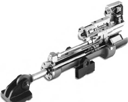
for example. A practical construction of a hydraulic linear servoactuator having the same working scheme
of Figure 21.88 is shown in Figure 21.89. It consists of a cylinder, a valve, and a position transducer
integrated in a single device.
A controlled, fluid-actuated system is a classical mechatronic system, as it combines mechanical and
fluid components, and control and sensing devices, and normally requires a simulation period for defining
the size and characteristics of the various elements so as to comply with the desired specifications.
The standardized symbols for the different components of hydraulic and pneumatic fluid systems, and
the definitions of the associated circuits, are defined in the standard, ISO 1219 “Fluid power systems and
components—Graphic symbols and circuit diagrams; Part 1: Graphics symbols, Part 2: Circuit diagrams.”
21.4.2.1 Fluid Servosystems
Fluid servosystems are devices for controlling a generically mechanical output power, either by controlling
a kinematic magnitude (servosystems for controlling position or speed) or by controlling an action (ser-
vosystems for controlling the force, torque, or pressure).
The output magnitude control action is obtained by controlling the fluid power, that is, by the power
of the fluid passing through the components of the servosystem.
Two large classes of fluid servosystems are usually present in current applications: hydraulic servosys-
tems, in which the operating fluid is a liquid, and pneumatic servosystems, in which the fluid used is
compressed air. The working pressure in hydraulic servosystems is typically comprised between 150 and
300 bar, while in the case of pneumatic systems, the pressure values are generally below 10 bar.
FIGURE 21.88 Scheme of a fluid power servosystem.
Position
transducer
Regulating
valves
PID
Force
disturbance
Piston
position
PlantPiston
Regulation
Position
reference
9258_C021_Sect002-005.fm Page 65 Wednesday, October 10, 2007 7:10 PM
21-66 Mechatronic Systems, Sensors, and Actuators
The first group obviously includes hydraulic oils, that is, fluid with high viscosity, now traditionally
used in servosystems in which a high controlled pressure is requested, but also combustible fluids, such
as automotive or aeronautical petrols (JPA, JPB,…), used in all the applications found in the fuel circuits
of combustion engines. Other servosystems include those which use both industrial and seawater as the
working fluid. The latter solution has unquestionable advantages in all naval and off-shore applications.
Pneumatic servosystems include all the industrial applications for automation of production and
process automation, and also the vehicular applications on means of air, sea, road, and rail transport.
The compressed air in these applications is generated by compressors using air drawn in from the
environment. Further applications include those in which the working fluid is not compressed air but a
particular gas. In this regard, there are servosystems with refrigerant fluids in the gaseous stage, in both
vehicular and industrial cryogenic systems, with fuel gases (LPG, methane, propane) in domestic appli-
cations, and with nitrogen in high-pressure applications.
It can be seen from this preliminary analysis that fluid servosystems are present both in the realization
of a product, being integral parts of the automated production process, along with the electric servo-
mechanisms, and as controlled actuation devices integrated in the product itself; in this regard we can
mention generic servoactuators installed on aeroplanes and increasingly in road vehicles today.
21.4.3 Hydraulic Actuation Systems
The components of a hydraulic actuation system are:
•
The pump, that is, the hydraulic power generation system
•
The actuator, that is, the element which converts hydraulic power into mechanical power
•
The valve, that is, the hydraulic power regulator
•
The pipes for connecting the various components of the actuation system
•
The filters, accumulators, and reservoirs
•
The fluid, which transfers the power between the various circuit elements
•
The sensors and transducers
•
The system display, measurement, and control devices
FIGURE 21.89 Hydraulic servocylinder (Hanchen).
9258_C021_Sect002-005.fm Page 66 Wednesday, October 10, 2007 7:10 PM
Actuators 21-67
21.4.3.1 Pumps
Pumps transform electrical or mechanical energy into hydraulic energy. They constitute the fluid flow
generator of the hydraulic system, as the pressure is determined by the fluid resistance downstream from
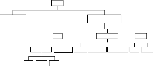
the generator. The main types of pumps are shown in Figure 21.90.
Centrifugal pumps permit high deliveries with low pressures. They do not have internal valves but
have a large clearance between the rotary part and stator part and guarantee a sufficiently stationary flow.
Vice versa, hydrostatic or positive displacement pumps, which are those most commonly used, guarantee
high pressures with limited deliveries. They have elements such as valves and caps, which permit sepa-
ration of the delivery zone from the intake zone, and they may introduce pulses in the flow in the delivery
line and generally require the use of a fluid with sufficient lubricating properties and load capacity, so
as to reduce the friction between the sliding parts of the pump. There are constant displacement and
variable displacement pumps.
The main positive displacement pumps belong to the gear, rotary vane, and piston types.
Gear Pumps
Gear pumps are subdivided into pumps with external gears, pumps with internal gears, and screw pumps.
In all cases, the pump is made up of two toothed wheels inserted into a casing with little slack so as to
minimize leakage.
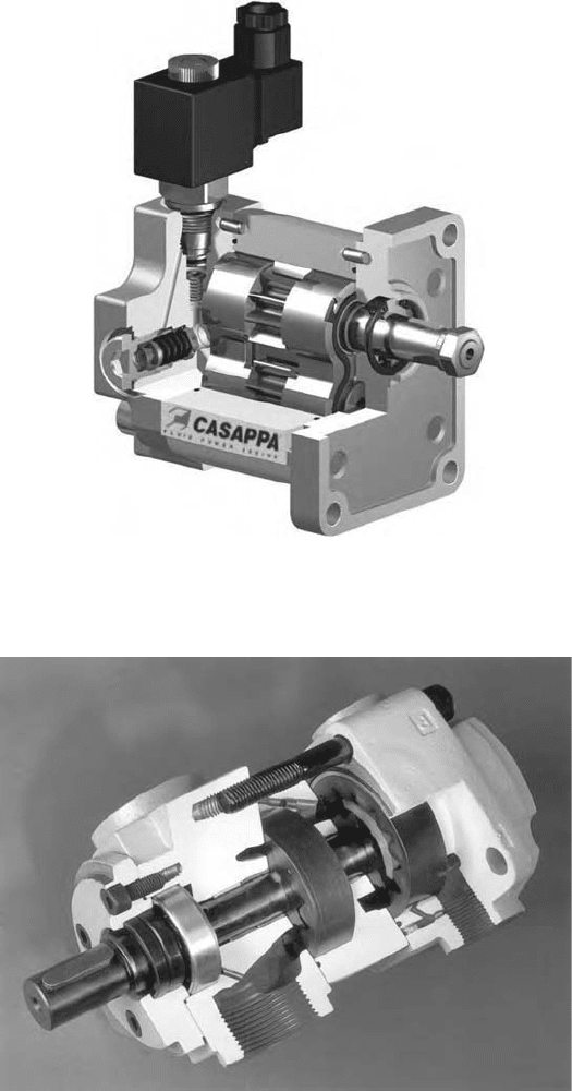
Figure 21.91 is a photograph of a pump with external gears. The opposed rotation of the wheels causes
the transfer of the oil trapped in the space between the teeth and walls of the gear from the intake to the
outlet. Depending on the form of the teeth, there are external gear pumps of the spur gear, helical gear,
and lobe gear types.
Pumps with internal gears are functionally similar to the above, but in this case the gears rotate in the
same direction. Figure 21.92 is a section plane of a two-stage pump. In screw pumps, which may have one
or more rotors, the elements have helical toothing similar to a threaded worm screw. Transfer of the fluid
takes place in an axial direction following rotation of the screw. These types of pump guarantee very
smooth transfer of the flow, with reduced pulsation and low noise levels.
The usual rotation speeds are between 1000 and 3000 rpm, with powers between 1 and 100 kW.
Delivery pressures can reach 250 bar, with higher values in the case of the pumps with external gears.
The flow transferred is a function of the pump displacement and the angular input speed, with values
comprised between 0.1 and 1000 cm
2
/rev. Double pumps can be used to increase these values. Gear
pumps have high performance levels, with values around 90%.
Rotary Vane Pumps
Vane pumps (Figure 21.93) generally consist of a stator and a rotor, which can rotate eccentrically with
respect to one another. Vanes can move in special slits placed radially in the stator or in the rotor and
FIGURE 21.90 Pumps classification.
Gear
LoabSpur Helical
Internal gear Axile
Rotary vane Piston
RadialBalanced vaneSimple vaneScrewExternal gear
Hydrostatic or
poistive dispalcement
Pumps
Centrifugal or
rotodynamic
9258_C021_Sect002-005.fm Page 67 Wednesday, October 10, 2007 7:10 PM
21-68 Mechatronic Systems, Sensors, and Actuators
delimit appropriate variable volumes. In Figure 21.93, as in most constructions, the vanes are borne by
the rotor which can rotate inside the stator. Rotation leads to the displacement of volumes of fluid
enclosed between two consecutive vanes from the intake environment to input into the delivery envi-
ronment. This type of pump permits a range of working pressures up to 100 bar and, compared with
gear pumps, guarantees lower pulsing of the delivery flow and greater silence.
FIGURE 21.91 External spur gear pump (Casappa).
FIGURE 21.92 Internal gear pump (Truninger).
9258_C021_Sect002-005.fm Page 68 Wednesday, October 10, 2007 7:10 PM
Actuators 21-69
Piston Pumps
Volumetric piston pumps can have one or more cylinders; that is, there may be one or more cylinders
with a piston sliding in each of them. Transfer of the volume of fluid from intake to delivery is determined
by the displacement of the piston inside the cylinder, which is provided with input and output valves
or shutters. Depending on the geometrical arrangement of the cylinders with respect to the rotating
motor shaft, piston pumps are subdivided into axial pumps (bent axis type and swash plate type) and
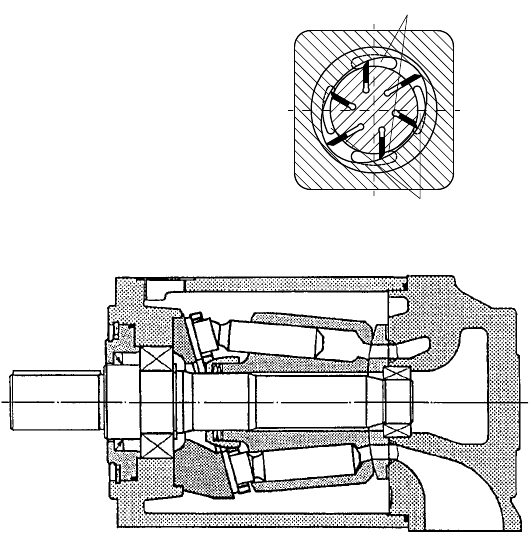
radial pumps. Figure 21.94 shows the plan of a fixed-displacement axial piston pump, of the swash plate
type. The working pressure range available with the aid of piston pumps is greater than in the previous
cases, being able to reach pressures in the order of 400–500 bar but with the disadvantage of more
uneven flow.
21.4.3.2 Motion Actuators
Motion actuators convert the hydraulic energy of the liquid under pressure into mechanical energy. These
actuators are therefore volumetric hydraulic motors and are distinguished, on the basis of the type of
movement generated, similar to what has been said about pumps, into rotary motors, semi-rotary motors
or oscillating ones, which produce limited rotation by the output shaft, and into linear reciprocating
motors, that is hydraulic cylinders.
Rotary and Semi-Rotary Motors
In construction terms, rotary motors are identical to rotary pumps. Therefore gear, vane, and piston
motors, radial or axial, are available. Obviously, the operating principle is the opposite of what has been
said for pumps. The symbols of hydraulic rotary motors are shown in Figure 21.95. Semi-rotary motors
generate the oscillating motion either directly, by means of the rotation of a vane connected to the output
shaft, or indirectly, by coupling with a rack, driven by a piston, with a toothed wheel connected to the
output shaft, as in the example in Figure 21.96. The semi-rotary vane motors produce high instantaneous
torsional torque on the output shaft; for this reason they are also called hydraulic torque-motors.
FIGURE 21.93 Rotary vane pump.
FIGURE 21.94 Axial piston swash plate pump (Bosch Rexroth).
Suction side
Pressure side
9258_C021_Sect002-005.fm Page 69 Wednesday, October 10, 2007 7:10 PM

21-70 Mechatronic Systems, Sensors, and Actuators
Linear Actuators
Linear hydraulic motors constitute the most commonly used type of actuator. They provide a rectilinear
movement realized by the stroke of a rod connected to a piston sliding inside the cylinder. A distinction
is made between single acting and double acting cylinders. The former only permit a single work stroke
and therefore the pressure of the fluid is exerted on the surface of the piston in one single direction; the
retract stroke is made by means of the force applied externally to the cylinder rod, or with the aid of a
helical spring incorporated with the actuator inside a chamber. The latter permit both strokes, so that
the fluid acts alternately on both faces of the piston, generating both the advance and retract strokes.
Double acting cylinders may have a single rod or a double through rod. These are composed of a tube closed
at the ends by two heads, and a mobile piston inside the barrel bearing one or two rods connected
externally to the load to move. As it is fitted with sealing gaskets, the piston divides the cylinder into two
chambers. By sending the oil under pressure into one of the chambers through special pipes in the heads,
a pressure difference is generated between the two surfaces of the piston and a thrust transmitted to the
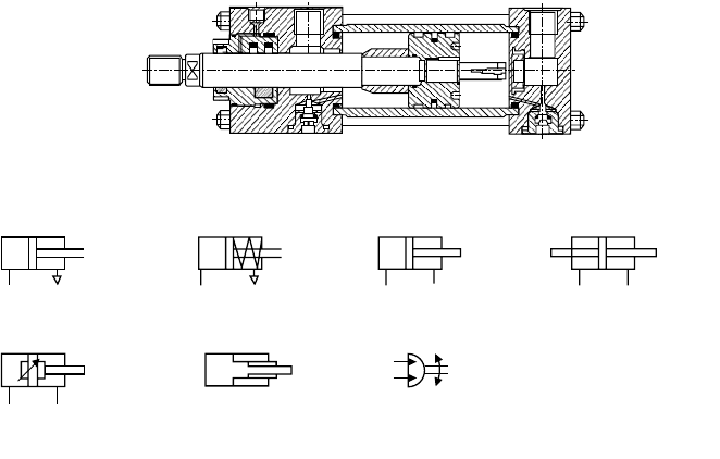
outside by the rod. Figure 21.97 shows the constructional solution of a hydraulic double acting cylinder
with a single rod. Single rod actuators are also known as asymmetrical cylinders because the working
area on the rod side is smaller than the area of the piston, as it is reduced by the section of the rod itself.
FIGURE 21.95 Symbols of hydraulic rotary motors.
FIGURE 21.96 Hydraulic rotary actuator (Parker Hannifin).
Varibale
dispalcement
motor
Bidirectional
motor
Unidirectional
motor
9258_C021_Sect002-005.fm Page 70 Wednesday, October 10, 2007 7:10 PM
Actuators 21-71
This involves actuating forces and feed speeds which are different in the two directions, with the same
feed pressure in the two thrust chambers.
Hydraulic actuators are able to support external overloads, as, if the load exceeds the available thrust
force, the rod stops or reverses, but generally does not suffer any damage. Cylinders may get damaged
however, or at least suffer a drop in performance, when they have to support loads which are not applied
along the axis of the rod, that is, with components in the radial direction, as reactions are generated on
the rod supports and piston bearings, which leads to fast wear of the same and reduces the tightness
with oil leakage as a result.
The main features of a linear actuator are its bore, its stroke, its maximum working pressure, the type
of working fluid, and the way its connections are fitted.
The symbols of the different types of actuators can be seen in Figure 21.98.
21.4.3.3 Valves
Valves are the components in hydraulic circuits that carry out the task of regulating the hydraulic power
sent to the actuator. Their role is to turn the oil flow on or off or to divert it according to needs, thereby
permitting adjustment of the two fundamental physical magnitudes of fluid transmission: pressure and
flow rate. They are subdivided as follows on the basis of the operations they carry out:
•
Directional valves
•
On-off valves
•
Pressure regulator valves
•
Flow-rate regulator valves
In servomechanism applications valves with the continuous positioning of the moving components in
them, said flow proportional valves or servovalves, and pressure proportional valves are used.
Directional Valves
Directional valves determine the passage and the flow direction of the oil current by means of the
movement of appropriate moving parts contained in them, actuated from outside. Directional valves,
FIGURE 21.97 Single rod double-acting piston actuator (Atos).
FIGURE 21.98 Actuators symbols.
Singal acting,
single ended actuator
Semi-rotary actuator
limited angle
Double acting, singal
ended telescopic
actuator
Double acting, singal
ended actuator with
variable cushioning
Double acting,
singal ended actuator
Double acting,
double ended actuator
Singal acting, spring
return actuator
9258_C021_Sect002-005.fm Page 71 Wednesday, October 10, 2007 7:10 PM
