Bichop R.H. (Ed.) Mechatronic Systems, Sensors, and Actuators: Fundamentals and Modeling
Подождите немного. Документ загружается.

21-82 Mechatronic Systems, Sensors, and Actuators
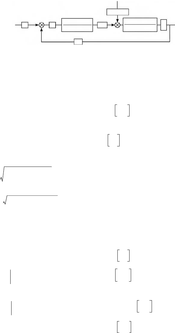
that the leaks are negligible, the diagram of the linearized system is shown in Figure 21.112, which
indicates:
where, in the above expressions:
proportional valve static gain
proportional valve flow gain
A
C
piston area [m
2
]
proportional valve flow-pressure gain
γ
coefficient of viscous friction
hydraulic stiffness in centred position [N/m]
V
T
total volume of the two chambers [m
3
]
M mass of the moving parts [kg]
FIGURE 21.112 Block diagram of the linearized model of an hydraulic servosystem with position control.
compensator transfer function [V/V]
static speed gain
static gain of the position transducer [V/m]
force constant
σ
n
natural frequency of the proportional valve [rad/s]
ζ
proportional valve damping factor
hydraulic resonance frequency [rad/s]
hydraulic damping factor
force disturbance time constant [s]
X
SET
V
SET
K
OLF
(τ s –1)
K
OLV
K
TP
K
R
e
G
c
e
c
–
–
+
+
F
E
V
RET
x
x
–
1
s
•
s
2
+ 2
n
s +
ζσ
σ
2
n
σ
2
n
s
2
+ 2
A
A
s +
ζ σ
σ
2
A
σ
2
A
G
C
K
OLV
K′
S
K
Q
A
C
A
C
2
K
PQ
γ
–
------------------------
=
m/s
V
---------
K
TP
K
R
=
K
OLF
K
PQ
A
C
2
K
PQ
γ
–
------------------------
=
m
sN
------
σ
A
C
0
M
-----
1 K
PQ
γ
/A
C
2
()–[]=
ζ
A
γ
MK
PQ
C
0
/A
C
2
()–
2 C
0
M 1 K
PQ
γ
/A
C
2
()–[]
--------------------------------------------------------
=
τ
A
C
2
C
0
K
PQ
---------------
=
K′
S
A
Vmax
V
max
-------------
=
m
2
V
------
K
Q
∂
Q
∂
A
V
---------
A
V0
,P
L0
=
m
3
s m
2
----------
K
PQ
Q
∂
P
L
∂
--------
A
V 0
,P
L0
=
m
3
s Pa
---------
N
s/m
---------
C
0
4
β
A
C
2
V
T
-------------=
9258_C021_Sect002-005.fm Page 82 Wednesday, October 10, 2007 7:10 PM

Actuators 21-83
The open loop transfer function is
(21.53)
Supposing G
C
to be constant, the static gain in open loop is
(21.54)
The closed loop transfer function is
(21.55)
where
The transfer function between output and disturbance, said dynamic compliance, is
(21.56)
Static compliance is
(21.57)
having put
G
OL
=
V
RET
e
-----------
G
C
K
OLV
K
TP
σ
n
2
s
2
2
ζσ
n
s
σ
n
2
++
------------------------------------
σ
A
2
s
2
2
ζ
A
σ
A
s
σ
A
2
++
----------------------------------------
1
s
--
⋅⋅⋅⋅=
K
0
G
C
K
OLV
K
TP
⋅⋅
G
C
K
S
′
K
Q
A
C
K
TP
A
C
2
K
PQ
γ
–
-----------------------------------
==
G
CL
=
x
X
set
--------
K
R
G
C
K
OLV
σ
n
2
σ
A
2
s
2
2
ζσ
n
s
σ
n
2
++()s
2
2
ζ
A
σ
A
s
σ
A
2
++()sG
C
K
OLV
σ
n
2
σ
A
2
K
TP
+
----------------------------------------------------------------------------------------------------------------------------------------
=
1
a
5
s
5
a
4
s
4
a
3
s
3
a
2
s
2
a
1
s 1+++++
------------------------------------------------------------------------------
=
a
5
1
σ
n
2
σ
A
2
K
0
------------------
, a
4
2
σ
n
σ
A
K
0
------------------
ζ
A
σ
n
-----
ζ
σ
A
------
+
==
a
3
1
K
0
-----
1
σ
n
2
-----
4
ζ
A
ζ
σ
n
σ
A
------------
1
σ
A
2
------
++
, a
2
2
K
0
-----
ζ
σ
n
-----
ζ
A
σ
A
------
+
, a
1
1
K
0
-----
===
G
FCL
x
F
e
----
K
OLF
τ
s 1–()s
2
2
ζσ
n
s
σ
n
2
++()
σ
A
2
s
2
2
ζσ
n
s
σ
n
2
++()s
2
2
ζ
A
σ
A
s
σ
A
2
++()sG
C
K
OLV
σ
n
2
σ
A
2
K
TP
+
----------------------------------------------------------------------------------------------------------------------------------------–==
x
F
e
----
s=0
K
OLF
G
C
K
OLV
K
TP
---------------------------
K
PQ
G
C
K
S
′
K
Q
A
C
K
TP
-----------------------------------
1
G
C
K
S
′
K
P
A
C
K
TP
-----------------------------------== =
K
PQ
K
Q
K
P
------
, K
P
P
L
∂
A
V
∂
---------
A
V0
, P
L0
pressure gain
Pa
m
2
------
==
9258_C021_Sect002-005.fm Page 83 Wednesday, October 10, 2007 7:10 PM

21-84 Mechatronic Systems, Sensors, and Actuators
Finally, a static stiffness is defined equal to
(21.58)
The predominant time constant, which is obtainable from the closed loop transfer function, is the
coefficient a
1
= 1/K
0
.
In conclusion, the following general considerations can be drawn:
•
The speed gain K
OLV
, and therefore the open loop static gain K
0
, depend to a considerable degree
on the flow gain K
Q
and increase with increases in K
Q
. K
Q
increases as P
S
increases, decreases as
∆P
L0
increases, and does not vary with A
V0
. In the hypothesis of
γ
below 1000 Ns/m, the effect of
K
PQ
is modest, practically negligible.
•
The force constant K
OLF
depends on the flow-pressure gain K
PQ
and increases with it. |K
PQ
| increases
with A
V0
and with ∆P
L0
, while it decreases as P
S
increases; therefore |K
OLF
| decreases as P
S
increases.
Leaks lead to an increase in K
OLF
.
•
Static stiffness depends considerably on the pressure gain of the valve and increases with it. Given
that K
P
decreases with the leaks, these lead to a reduction in static stiffness. Furthermore, given
that |K
PQ
| increases with A
V0
while K
Q
does not vary with A
V0
, the pressure gain decreases with the
increase in A
V0
, and therefore static stiffness decreases if the valve is working in greater opening
conditions.
Furthermore, given that |K
PQ
| decreases as P
S
increases, while K
Q
increases as P
S
increases, the
pressure gain increases as P
S
increases and therefore, the static stiffness increases with P
S
.
•
The hydraulic resonance frequency increases with the increase in hydraulic stiffness C
0
and
decreases with the increase of the mass M. It is practically uninfluenced by the flow-pressure gain
K
PQ
if
γ
< 1000 Ns/m.
•
The predominant time constant is inversely proportional to the speed gain, decreases as K
Q
increases, that is it decreases as P
S
increases, increases as ∆P
L0
increases, and is indifferent to
variations in A
V0
.
21.4.5 Pneumatic Actuation Systems
Just as described for the hydraulic system, the components of a pneumatic actuation system are:
•
The compressed air generation system, consisting of the compressor, the cooler, possibly a dryer,
the storage tank, and the intake and output filters
•
The compressed air treatment unit, usually consisting of the FRL assembly (filter, pressure regu-
lator, and possibly a lubrifier), which permits filtration and local regulation of the supply pressure
to the actuator valve
•
The valve, that is, the regulator of the pneumatic power
•
The actuator, which converts the pneumatic power into mechanical power
•
The piping
•
The sensors and transducers
•
The system display, physical magnitude measurement, and control devices
Some of the components of the pneumatic actuation system such as the compressors, treatment units,
and some valves used in pneumatic servosystems are described below. The actuators are similar in
function and construction to hydraulic ones, though they are built slightly lighter because of the lower
working pressure.
F
e
x
----
s=0
G
C
K
S
′
K
P
A
C
K
TP
=
9258_C021_Sect002-005.fm Page 84 Wednesday, October 10, 2007 7:10 PM
Actuators 21-85
21.4.5.1 Compressors
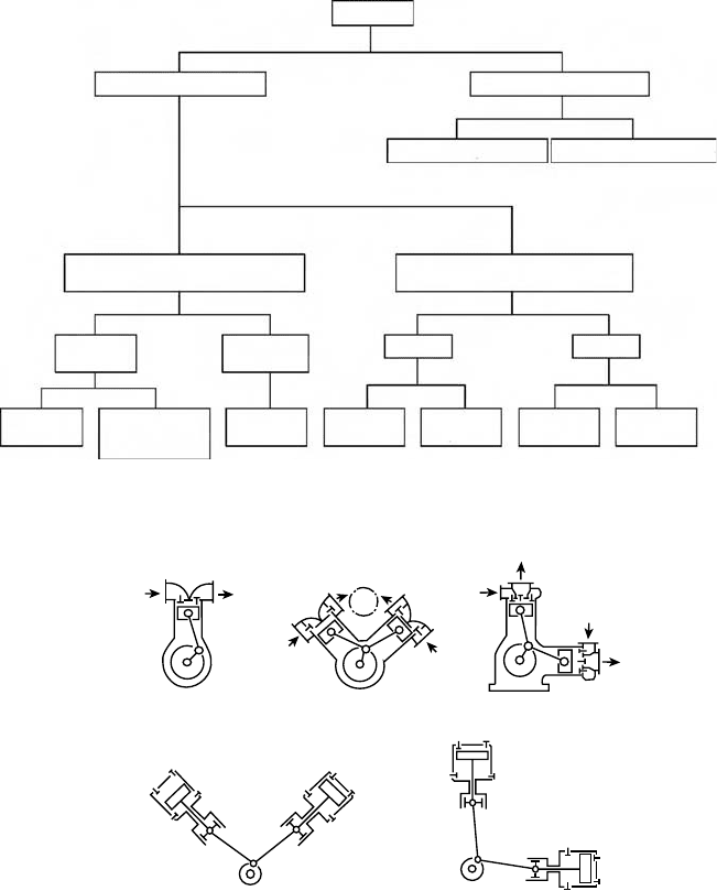
The types of compressors used to produce compressed air are summarized in Figure 21.113. In volumetric
compressors, the air or gas is sucked in by means of a valve in the compression chamber where its volume
is reduced to cause compression of the gas. Opening of the delivery valve, when a predetermined pressure
has been reached, results in the distribution of the air mass to the user.
Vice versa, in dynamic compressors or turbocompressors, the kinetic energy is converted into pressure
energy transferred to the gas as a result of the rotary motion of the impeller.
Alternating piston compressors determine the compression of the gas as an effect of the motion of
the piston, moved by a connecting rod and crank mechanism, inside a gas-tight cylinder. They can be
single and double acting, with one or more pistons and one or more stages (Figure 21.114). They make
it possible to obtain pressures of hundreds bar, where there are several stages, and flow rates of thousands
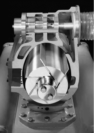
of cubic meters per hour, in the case of several cylinders. Vane compressors (Figure 21.115) have a rotor,
fitted eccentrically with respect to the axis of the cylinder in which it rotates, which leads to a certain
FIGURE 21.113 Classification of pneumatic compressors.
FIGURE 21.114 Piston compressors: (a) single action and (b) double action.
Compressors
Roots
compressors
Two shaftOne shaft
Screw
compressors
Scroll
compressors
Vane
compressors
Membrance
compressors
Swash plate
and wobble plate
compressors
Piston
compressors
Displacement compressors
Radial turbo compressors
Rotary piston compressors
oscillating
Without crank
mechanism
With crank
mechanism
Reciprocating piston compressors
oscillating
Axial turbo compressors
Dynamical type compressors
(b)
(a)
9258_C021_Sect002-005.fm Page 85 Wednesday, October 10, 2007 7:10 PM
21-86 Mechatronic Systems, Sensors, and Actuators
number of vanes which can move radially with respect to its axis. In the continuous rotation motion of
the rotor, the vanes are centrifuged in contact with the seat of the stator, isolating chambers whose volume
varies progressively with the angular stroke, guaranteeing input suction on the one hand, and a com-
pressed gas output on the other. The compression pressures are below 15 bar, with maximum flow rates
of 500 m
3
/h. Compared with reciprocating piston compressors, they have less flow pulsation, fewer
vibrations, and are more compact.
Screw compressors have two rotors rotating in opposite directions inside a stator, one with convex
lobes and the other with concave lobes. The coupling of the profiles of the two rotors leads to a reduction
of the volume during the angular stroke and consequent compression of the gas. With pressures typically
below 15 bar, they provide a sufficiently continuous flow, up to values of about 3000 m
3
/h.
In the same way, Roots compressors, also known as superchargers, are made up of two figure-of-eight-
shaped rotors counter-rotating inside a stator in such a way as to transport volumes of gas from suction
to delivery. Their efficiency is low because of the leakage between the rotors themselves and between the
lobes and the casing, and they are, therefore, used for low compression pressures, below 2 bar. However,
they do permit operation without lubrication, like screw compressors, so that oil-free air can be obtained.
Both axial and radial dynamic compressors are used to obtain high compressed air flow rates from a
few thousand to 100,000 m
3
/h.
21.4.5.2 Compressed Air Treatment Units
Pneumatic supply to a servosystem is generally provided by a local gas treatment unit, consisting of a
filter, connected to a compressed gas distribution and generation network, a pressure regulator, and in
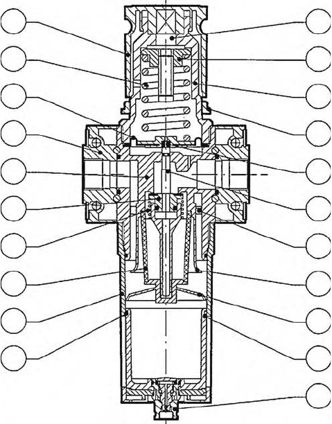
case a lubricator L. Figure 21.116 shows an example of an integrated filter device and pressure regulator.
The air first passes through the filter and is filtered by the deflector while the solid and liquid impurities
in contact with the walls are deposited on the bottom of the cup, also as an effect of the conical bottom
screen, located below the porous cylindrical element in sintered bronze or fabric. The filtered air then
flows into the inlet of the pressure regulator, made up of an obturator in equilibrium between pressure
FIGURE 21.115 Rotary vane compressor (Pneumofore).
9258_C021_Sect002-005.fm Page 86 Wednesday, October 10, 2007 7:10 PM
Actuators 21-87
forces. Control of the downstream pressure is determined by the position of the main obturator, which
regulates the flow towards the outlet. The passage aperture is closed when the force due to the downstream
pressure, acting on a diaphragm and on a translating piston, is in equilibrium with the force of the top
spring, the preload of which is set by the rotation of the control knob. Vice versa, if the pressure force is
below the desired value, the flow sent to the user tends to compensate for the pressure error with
consequent closing of the obturator again when the set point has been reached. The opposite situation
occurs if the regulated pressure is above the requested value, so that an aperture passage opens between
the user and discharge.
21.4.5.3 Pneumatic Valves
Pneumatic valves are functionally similar to those used in hydraulic systems, so that reference should be
made to the general considerations described above. In particular, this is also valid for the directional
valves of the digital and proportional types. Even in pneumatic systems, there are digital spool or poppet
two-, three-, or four-way distributors, with two or three working positions, and actuated manually,
mechanically, pneumatically, and electrically.
Flow proportional valves are substantially similar to hydraulic ones and are available both with the
torque motor electromechanical converter (servovalve), and with servosolenoid acting directly on the spool.
As well as these components for controlling the gas flow, digital electrically controlled two- or three-
way valves are also used, and their control signals are modulated using PWM (pulse width modulation),
PFM (pulse frequency modulation), PCM (pulse code modulation), PNM (pulse number modulation),
or a combination of these.
FIGURE 21.116 Pneumatic filter/pressure reducer (Metal Work).
2
6
8
20
1
11
12
16
21
18
3
4
5
9
10
13
14
15
17
19
7
9258_C021_Sect002-005.fm Page 87 Wednesday, October 10, 2007 7:10 PM
21-88 Mechatronic Systems, Sensors, and Actuators
As far as pressure regulation valves are concerned, three-way pressure proportional valves are available
for pneumatic actuation which convert an electrical reference signal with standardized input into a
controlled output pressure with good dynamics and high precision.
PWM (Pulse Width Modulation) Valves
The structure of PWM valves is similar to the corresponding electrically controlled unistable digital
valves, but uses a technique for modulating the width of the pulses sent to the solenoid for supplying
proportional control of the flow rate. This technique envisages that the input voltage reference analog
signal V
REF
(for example 0–10 V) is converted by a special driver into a digital V
PWM
(ON/OFF) signal
with pulse duration proportional to the input signal. Alternatively, the modulated signal can be generated
directly by a digital controller, such as a PLC.
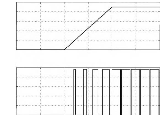
Figure 21.117 shows the PWM operating principle. The digital voltage signal sent to the valve solenoid
is made up of a pulse train, with a constant amplitude, with a constant period T, but with the duration
t of every pulse being a linear function of the analog value of the reference voltage. The average valve
opening value, and therefore an initial approximation of the generated flow, is a function of the duration
t of the pulse, in particular of the duty cycle t/T, and increases as the latter increases.
PWM valves generally do not have any feedback, so that the value of the downstream pressure, and
therefore of the flow rate, depends on the type of pneumatic circuit present.
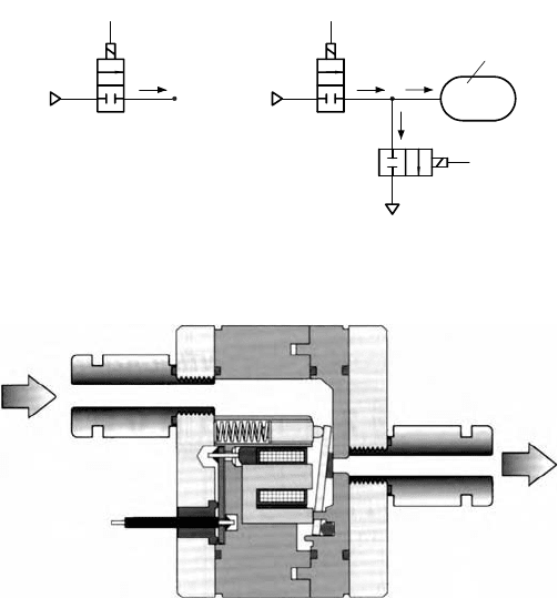
Figure 21.118 shows two plans which depict operation of the two-way, two-position valves, with PWM,
used as a flow regulator (Figure 21.118a) and as a pressure regulator (Figure 21.118b). In plan a, the
valve proportionally controls the flow which transits between the two points at pressure P
S
(feed pressure)
and at pressure P
V
(downstream pressure) maintained constant. In this case, this flow is only a function
of the aperture of the valve and therefore the proportionality is of the linear type. In plan b, the cross-
fitted valves control the pressure P
R
, for example, within a fluid capacity of volume V, respectively
regulating the mass flow rate G
1
and discharge flow G
2
. The time gradient for the controlled pressure P
R
corresponds to the resulting flow G entering the reservoir.
FIGURE 21.117 PWM (pulse width modulation) input and output signals.
0.250.1
0
10
8
6
4
2
20
V
pwm
[V]
V
ref
[V]
0
0
0
0.1
0.2 0.3
0.25
25
10
15
5
0.2 0.3
0.05
0.05
0.15
Time[s]
Time[s]
0.15
9258_C021_Sect002-005.fm Page 88 Wednesday, October 10, 2007 7:10 PM
Actuators 21-89
The parameters affecting the performance of a regulation made by a PWM on/off valve are as follows:
•
Valve opening and closing times
•
Dependence on the opening/closing times of the upstream and downstream pressures
•
Valve size
•
Period T or modulation carrier frequency f = 1/T
•
Working life of the valve
While small opening/closing times and high flow capacity are always antithetical characteristics in an
on/off valve, when designing the system it is always necessary to find a compromise between the need
for good control resolution and linearity and a high response dynamic.
In pneumatic servosystem applications, typical carrier frequency values f = 1/T range between 20 and
100 Hz, so that valves with opening/closing times of 1 ÷ 5 ms are used.
An example of a normally closed 2/2 valve that guarantees minimum opening times (below 1 ms with
speed-up command) can be seen in Figure 21.119. These characteristics are obtained by reducing the
mass of the moving parts, with the use of a poppet connected to a small oscillating bar, while practically
eliminating the friction between the parts in relative motion.
Proportional Pressure Regulator Valves
These valves are normally three-way, with double poppets or with spool. Poppet valves operate in a
similar way to pressure regulator valves. In the same way as with pressure regulators, the poppet which
separates the high pressure environment from the regulated pressure one is in equilibrium between the
force due to the regulated pressure and that exerted by the action of the control block. The latter can
directly be the force of the servosolenoid armature, or that due to a pressure controlled by the control
block which acts on a piston or on a diaphragm linked with the poppet.
FIGURE 21.118 PWM (pulse width modulation) digital valves: (a) flow regulator and (b) pressure regulator.
FIGURE 21.119 Two-way digital poppet valve (Matrix).
V
PWM1
G
2
G
1
P
S
P
S
P
V
P
V
P
R
w
w
w
V
G
(b)
(a)
G
V
PWM2
V
PWM
9258_C021_Sect002-005.fm Page 89 Wednesday, October 10, 2007 7:10 PM
21-90 Mechatronic Systems, Sensors, and Actuators
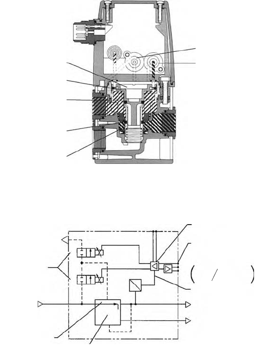
Figure 21.120 shows an example of a pressure proportional valve with double poppets. The ports at
supply pressure, controlled pressure, and discharge are respectively indicated by P, A, and E. In the
position indicated in the figure, the supply poppet 2 is at the top end of its stroke, as the seal 1 is against
the fixed seat. In the same way, the regulating poppet 3 is in contact with the poppet 2 by means of the
seal 5. The opening of the feed aperture, between the port P and the port A, is determined by the
equilibrium of the forces acting on the piston of poppet 3, in particular the force F
R
of the regulation
pressure P
R
in the servochamber 4 directed downwards, and the force F
C
due to the action of the regulated
pressure P
c
on the outlet, directed upwards. If F
R
= F
C
, the moving bodies in the valve are in the positions
shown in the figure, so that the chamber at controlled pressure P
C
is isolated both from supply and
discharge. If F
R
> F
C
, then the two poppets move downwards and the feed aperture is opened so as to
convey the air mass towards the output and rebalance the pressure P
C
at the desired value. In the opposite
case, if F
R
< F
C
, the regulating poppet moves upwards, but while remaining at the top end of its stroke,
the seal 5 opens and permits the passage of the masses from port A to the exhaust E.
In Figure 21.120, 6 and 7 indicate the PWM on/off valves, which regulate the pressure P
R
of the
servochamber 4.
The pneumatic control plan of the valve is shown in Figure 21.121. The two 2-way PWM valves receive
the modulated control signal from the regulation block. These are fitted in such a way that one controls
FIGURE 21.120 Pressure proportional valve (Parker).
FIGURE 21.121 Pneumatic control scheme of the pressure proportional valve.
3
5
1
2
6
7
Inlet P
Exhaust E
(B)
Pressure
sensor
(C)
PWM
solenoid
valves
Outlet A
4
A - regulated pressure
2.9 to 145 PSIG
(0.2–10bar)
E exhaust
Pressure
sensor
24VDC
U
+
–
P
R
W
W
P
Differential
amplifier
U/I - Control signal
(0–10 VDC, 4–20 mA)
Sensor output
singals
Feedback loop
(1/4” &1/2” versions only)
14.5 to 174 PSIG
(1–12 bar)
Pilot
chamber
Inlet
pressure
Pulse width
modulated 2-way
solenoid valves
4-20mA )
or
0/24VDC Alarm
(0–10VDC
9258_C021_Sect002-005.fm Page 90 Wednesday, October 10, 2007 7:10 PM
Actuators 21-91
a flow entering the servochamber 4 (see Figure 21.120) while the other controls the flow exiting towards
discharge. By means of appropriate action, the control signal is converted into a pressure proportional
signal.
21.4.6 Modeling a Pneumatic Servosystem
The circuitry plan of a pneumatic servosystem capable of controlling the position, speed, or force can
be similar to that shown in Figure 21.109 for hydraulic actuation. The signal of the transducer of the
desired magnitude must be specially fed back in a closed loop on the regulator depending on the
controlled magnitudes.
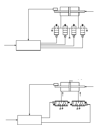
In the plan in Figure 21.122, the axial position of the piston, fed back by means of the position
transducer, is determined by controlling the pressure in thrust chambers 1 and 2 by means of the flow
proportional interfaces. The position reference is compared with the feedback signal and the error is
compensated in a control regulator. On the basis of the valve opening strategy used, the signal is sent to
the regulating valves which feed the chambers of the piston, hypothesized to be symmetrical. The pressure
forces acting on the thrust surfaces of the piston oppose the external force disturbance. The circuitry
plan hypothesizes the use of four digital valves each with two unistable ways, electrically controlled. This
solution makes it possible to use small-sized valves, with resulting high bandwidth, which must be
compatible with the overall bandwidth requested by the pneumatic servosystem. In this solution, the
proportionality of the opening of the valves is obtained by pulse width modulation of the digital signal.
Each pair of valves V
11
, V
12
and V
21
, V
22
constitutes a three-way valve the output of which is connected
to a piston chamber, so that the scheme in Figure 21.122 can be equivalent to that in Figure 21.123 with
the three-way analogically controlled valves V
1
and V
2
.
The cylinder model envisages a system with three-differential equations, two of continuity of the air
mass in the chambers and one of dynamic translation equilibrium.
FIGURE 21.122 Scheme of a pneumatic servosystem with two-ways digital valves.
FIGURE 21.123
Scheme of a pneumatic servosystem with three-ways proportional valves.
Position
reference
Regulation
and PWM
Position
transducer Piston
Force
disturbance
v
12
v
11
v
21
v
22
Position
reference
Regulation
Position
transducer
Force
disturbance
Piston
v
1
G
1
G
2
v
2
P
2
P
2
P
s
P
s
v
ref 1
v
ref 2
x,x, x,
9258_C021_Sect002-005.fm Page 91 Wednesday, October 10, 2007 7:10 PM
