ASM Metals HandBook Vol. 14 - Forming and Forging
Подождите немного. Документ загружается.

0.4 ( )
(b)
0.8 ( )
(b)
1.2 ( )
(b)
0.4 ( )
(b)
0.8 ( )
(b)
1.2 ( )
(b)
C11000 372 (54) 352 (51) 352 (51) 365 (53) 331 (48)
345 (50)
C17200
(c)
896 (130) 896 (130) 896 (130) 896 (130) 896 (130)
896 (130)
C17500
(c)
. . . . . . 724 (105) . . . . . .
724 (105)
C15100 428 (62) 400 (58) 400 (58) 407 (59) 400 (58)
400 (58)
C19400 538 (78) 510 (74) 496 (72) 517 (75) 496 (72)
490 (71)
C19500 614 (89) 572 (83) 572 (83) 592 (86) 572 (83)
558 (81)
C19700 538 (78) 510 (74) 496 (72) 517 (75) 496 (72)
490 (71)
C23000 593 (86) 593 (86) 593 (86) 572 (83) 552 (80)
538 (78)
C26000 662 (96) 662 (96) 662 (96) 627 (91) 524 (76)
524 (76)
C35300 641 (93) 572 (83) 572 (83) 496 (72) 483 (70)
469 (68)
C41100 517 (75) 496 (72) 496 (72) 468 (68) 448 (65)
434 (63)
C42500 621 (90) 621 (90) 621 (90) 552 (80) 475 (69)
462 (67)
C50500 490 (71) 469 (68) 469 (68) 490 (71) 468 (68)
469 (68)
C51000 710 (103) 662 (96) 648 (94) 621 (90) 572 (83)
538 (78)
C52100 765 (111) 745 (108) 731 (106) 614 (89) 558 (81)
552 (80)
C63800 827 (120) 807 (117) 793 (115) 724 (105) 696 (101)
696 (101)
C65400 745 (108) 731 (106) 731 (106) 627 (91) 627 (91)
627 (91)
C66600 669 (97) 655 (95) 641 (93) 613 (89) 586 (85)
579 (84)
C68800 786 (114) 744 (108) 745 (108) 786 (114) 745 (108)
731 (106)
C70250
(c)
690 (100) 655 (95) . . . 552 (80) 517 (75)
. . .
C70600 524 (76) 496 (72) 496 (72) 489 (71) 483 (70)
483 (70)
C72400
(c)
793 (115) 690 (100) 621 (90) 793 (115) 690 (100)
621 (90)
C72500 572 (83) 517 (75) 517 (75) 531 (77) 504 (73)
503 (73)
C73500 579 (84) 579 (84) 579 (84) 525 (76) 518 (75)
517 (75)
C74000 648 (94) 600 (87) 586 (85) 593 (86) 565 (82)
552 (80)
C75200 579 (84) 579 (84) 579 (84) 558 (81) 558 (81)
558 (81)
C77000 807 (117) 751 (109) 717 (104) 758 (110) 696 (101) 676 (98)
"Good way" and "Bad way" refer to the orientation of the bend with respect to the sheet or strip rolling direction (see Fig. 13
). Note:
Tensile strengths of 965 and 1103 MPa (140 and 160 ksi) are available in 0.25 and 0.5 mm (0.010 and 0.020 in.) thicknesses with
specially supplied mill tempers.
Source: Ref 2
(a)
Sheet thickness, mm (in.).
(b)
Bend radius, mm (in.).
(c)
Mill hardened to strength shown, then formed.
The practice of cold rolling to increase strip temper degrades bend formability. However, it is often used because most
alloys still exhibit useful bend formability at modest cold-rolling reductions. Product applications that require both high
strength and good bend performance are usually satisfied by selecting copper alloys that are precipitation and/or solute
strengthened with additions that greatly increase the work-hardening rate and thus minimize cold-rolling requirements to
achieve the desired strength.
Bend formability is typically dependent on bend direction with respect to strip-rolling direction (Fig. 13 and Table 6). All
cold-rolled materials exhibit directionality. The extent of bend directionality varies from alloy to alloy, but always
increases with increasing cold reduction. Bend directionality results from the development of strong textures during
rolling. Copper alloys with low stacking fault energy, such as Alloy C26000 (cartridge brass), develop strong {110}
<112> textures during rolling and can exhibit bend directionality even at approximately 30% cold-rolling reduction.
Dilute copper alloys and copper-nickel alloys do not develop well-defined rolling textures, and they show less bend
directionality even at high (70%) cold-rolling reductions. In general, sharper bends can be made in the good-way than in
the bad-way orientations for alloys that are cold rolled and/or solute strengthened. Bend anisotropy in precipitation-
hardening systems is strongly process dependent.
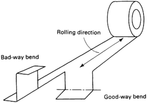
Fig. 13
Bend formability of copper alloys as a function of rolling direction. Bends with the axis transverse to the
rolling direction are termed good-way bends; bends with the axis parallel to the rolling direction are bad-
way
bends. See also Table 6. Source: Ref 3
Figure 14 shows the effects of bend directionality on part layout. This part includes both good-way and bad-way bends. If
the part were fabricated from an alloy with strong bend directionality--for example, phosphor bronze (Alloy C51000) in
spring temper--the part layout would be restricted to avoid failure at bad-way bends. With alloys such as C68800 or
C72500, which exhibit significantly less bend directionality, the part layout is not as restricted. It is not always possible to
orient parts to minimize web scrap, regardless of the alloy selected, because tool design and part-handling and transfer
costs may override the cost penalty of poor strip utilization.
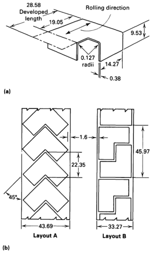
Fig. 14 Impact of bend anisotropy on part layout. (a) Hypothetical part, which has equal-
radius bends at 90°
orientations in the plane of the strip. Selection of the appropriate copper strip alloy for this applicatio
n depends
on the material strength and the bend properties in the relevant orientations. (b) Potential nesting of blanks for
the part shown in (a). Layout A is required for directional alloys such as C51000 and results in 38% scrap; a
nondirectional alloy such as C68800 would allow the more efficient layout B, with 23% scrap.
Dimensions given
in millimeters (1 in. = 25.4 mm). Source: Ref 3.
Special Considerations. The values listed in Table 6 for the minimum bend radii of various alloys as a function of
temper are approximate; actual results can deviate because of tool condition and shop practice. The bend performance
required also depends on the part application. For example, orange peel (surface roughening) is unacceptable if the part is
to be plated or subjected to other finishing operations and if appearance is important. Often, more than one alloy is
available that will meet product requirements. In the absence of other limitations, bend formability may be the deciding
factor in alloy selection.
The bend performance of copper alloy strip degrades as bend angle increases; that is, a 180° bend is more severe than a
90° bend angle. The effect of bend angle on bend formability is more severe as gage increases and/or bend radius
decreases. Bend performance improves as the width-to-thickness ratio of the bend region is reduced to values of less than
8 to 1. Reducing the width-to-thickness ratio can enhance bend performance by as much as three times.

References cited in this section
2.
T.E. Bersett, Back to Basics: Properties of Copper Alloy Strip for Contacts and Terminals, in
Proceedings of
the Fourteenth Annual Connector Symposium, Electronic Connector Study Group, 1981
3.
J.H. Mendenhall, Ed., Understanding Copper Alloys, Olin Corporation, 1977
Forming of Copper and Copper Alloys
Frank Mandigo and Jack Crane, Olin Corporation
Drawing and Stretch Forming
In drawing and stretch forming, a suitably shaped blank of sheet metal is drawn or formed into a die cavity to produce a
part. A clamping ring, draw beads, and/or other restraints are usually applied at the periphery of the blank to prevent
wrinkling and/or tearing of the blank as it is drawn or formed into the die cavity. The complexity of the edge restraint
required is usually directly proportional to the complexity of the final part.
A deep-drawn part is characterized by having a depth greater than the minimum part width. A deep-drawn part can be
fabricated in a single drawing step or in multiple steps by redrawing preforms developed by deep-draw, shallow-draw,
and/or stretch-forming methods. Ironing can be used during redrawing to control the wall thickness of the final part.
Additional anneals may be required between redrawing steps.
A shallow-drawn part has a depth less than the minimum part width and is usually formed in one process step. It can be a
final part or the preform for deep drawing.
A stretch-formed part is fabricated by pressing a punch into a blank that is fully or partially restrained at its periphery to
develop positive biaxial strain on the part surface. A stretch-formed part can be a final part or the preform for drawing
operations. Additional information on drawing and stretch forming is available in the articles "Deep Drawing" and
"Stretch Forming" in this Volume.
Materials Characteristics and Effects of Alloy Composition and Temper
Single-Step Drawing. Copper alloys that have high r values will provide the largest limiting draw ratio in a single
deep-draw step. The r value is defined as the ratio of true width strain to true thickness strain in the region of uniform
uniaxial elongation during a tensile test. It measures the resistance of a material to thinning. The r value correlates with
deep-drawing performance because it reflects the difference between the load-carrying capability of the cup sidewall and
the compression load required to draw in the flange of the cup or blank during a deep-drawing operation.
The deepest single-step draws (highest LDR) can be made with Alloy C52100, followed by the brasses (in order of
decreasing zinc level) and by copper. The LDR of cartridge brass (Alloy C26000) increases as its grain size increases.
Multiple-Step Deep Drawing. The number of redrawing steps and the frequency of intermediate annealing
treatments required depend on the initial preform geometry, the extent of ironing required, and the work-hardening rate of
the particular alloy. Fewer redrawing steps are required if the preform geometry closely matches that of the final part. The
trade-offs involved in selecting a fabrication procedure for the initial preform (for example, deep drawing, shallow
drawing, or stretch forming) are complex.
In contrast to single-step deep drawing, in which alloys with high work-hardening rates give the highest LDR, copper
alloys with lower work-hardening rates can be redrawn and ironed more times without intermediate annealing. The curves
shown in Fig. 15 suggest that Alloy C11000 (electrolytic tough-pitch, ETP, copper) will possess better redrawing and
ironing characteristics and will require lower press forces than copper alloys with solute additions of zinc, tin, and/or
silicon.
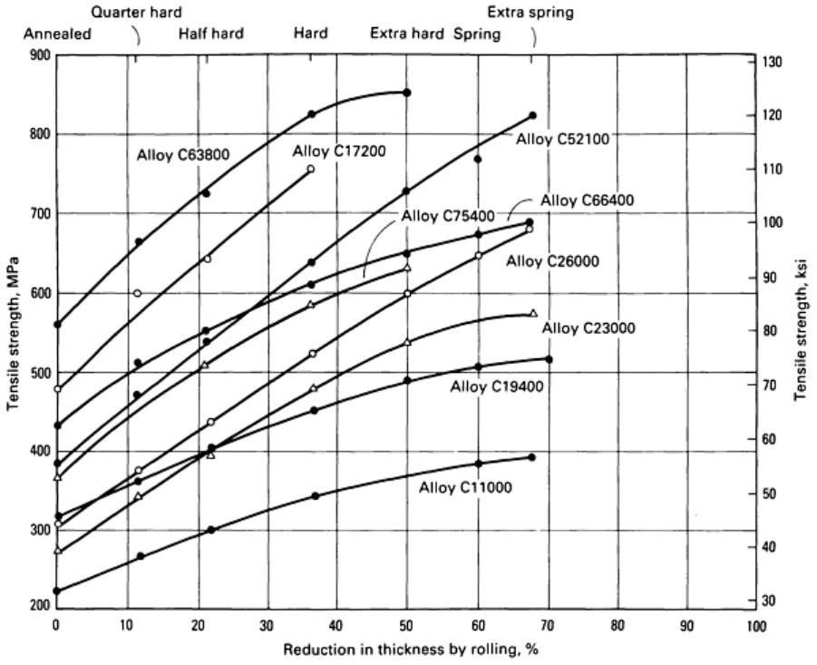
Fig. 15
Redrawing characteristics of 1.0 mm (0.040 in.) thick sheets of several copper alloys. Curves of lower
slope indicate a lower rate of work hardening and therefore a higher capacity for redrawing. Source: Ref 3.
In general, successively smaller reductions are selected at each redrawing step to ensure that the punch forces required to
decrease the flange circumference do not exceed the load-carrying capability of the part sidewall. The magnitude of the
incremental steps of redrawing is decreased if the part sidewall is to be ironed. Ironing increases the strength of the
sidewall and flange proportionally to the distance from the cup bottom. In some applications, redrawing capacity can be
improved by increasing the temper of the initial strip to enhance the load-carrying capability at the junction of the part
sidewall and the cup bottom. The alternative is to use a stronger alloy.
Stretch Forming. The stretch formability of copper alloys correlates with the total elongation measured in a tension
test. Annealed alloys that show high work-hardening rates offer the best stretch-forming characteristics. Improved
combinations of strength and stretch formability are achieved by solute elements that greatly increase the work-hardening
rate. Cold rolling to increase strip temper (strength) significantly reduces stretch formability.
The variation of tensile elongation with cold-rolling reduction for copper alloys is shown in Fig. 16. These data indicate
that high-tin and high-zinc alloys offer the best combinations of strength and stretch formability.
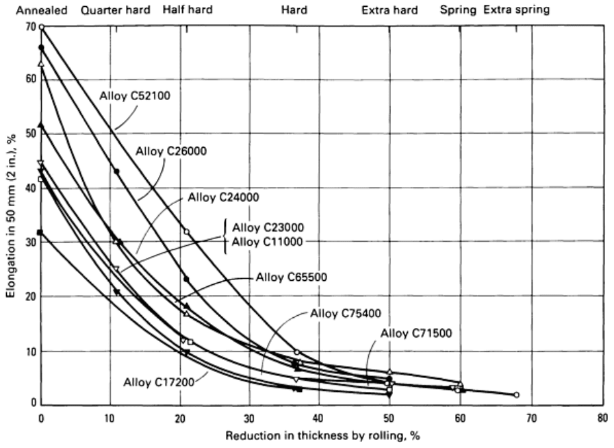
Fig. 16 Stretch-
forming characteristics of 1.0 mm (0.040 in.) thick copper alloys. Elongation values for a given
percentage of cold reduction indicate the remaining capacity for stretch forming in a single operation.
Source:
Ref 3.
Specific Characteristics of Copper Alloys. The higher-zinc brasses, such as Alloy C24000 (low brass), Alloy
C26000 (cartridge brass), and Alloy C26200 (high brass), have strengths comparable to those of low-carbon steels and
high ductilities. They are outstanding materials for deep drawing and stretch forming.
Many other families of copper alloys also have good deep-drawing and stretch-forming properties. Phosphor bronze A
(Alloy C51000) has an excellent combination of high strength and high ductility and is used to form deep-drawn thin-wall
shells that are then annealed and corrugated to produce bellows with high fatigue strength, corrosion resistance, and
excellent flexibility.
The nickel silvers (copper-nickel-zinc) are white copper alloys that also have excellent deep-drawing characteristics
similar to those of the high-zinc brasses. However, they have somewhat higher work-hardening rates and require more
intermediate annealing for redrawing than cartridge brass. In the fully annealed condition, Alloy C63800 (Cu-3Al-2Si-
0.4Co) also exhibits good deep drawability (similar to that of the nickel silvers). Annealed high-zinc leaded brasses are
suitable for shallow-drawn parts, such as garden-hose coupling nuts.
Copper-zinc-tin alloys such as C40500, C41100, C42200, and C425000 respond well to drawing and redrawing
operations. With regard to deep-drawing properties, C40500 and C41100 are similar to the high-copper brasses, and
C42200 and C42500 are similar to C24000.
Beryllium coppers can be drawn in the solution-annealed temper and then age hardened. For example, annealed Alloy
C17200 has been deep drawn to 80% reduction before annealing. Parts drawn from beryllium-copper alloys can
subsequently be heat treated to produce tensile strengths to 1275 to 1380 MPa (185 to 200 ksi).
There are many other special-purpose coppers and copper alloys. By examining their compositions and mechanical
properties carefully and by comparing them with standard alloys, the user can estimate how they will respond in deep-
drawing applications.
Grain Size Effects. For the coppers and single-phase alloys, grain size is the basic criterion by which deep drawability
and stretch forming are measured. In general, for a given alloy and sheet thickness, ductility increases with grain size, and
strength decreases. However, when grain size is so large that there are only a few grains through the thickness of the sheet
or strip, both ductility and strength, as measured by tensile testing, decrease. Figure 17 illustrates how elongation changes
with grain size for three different thicknesses of Alloy C26000 (cartridge brass). General recommendations for the grain
size of annealed strip for drawing and stretch-forming operations are provided in Table 7, along with the expected surface
characteristics.
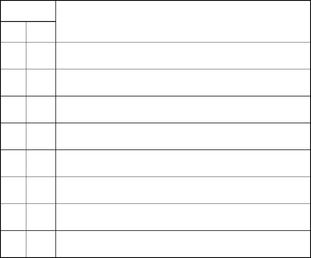
Table 7 Available grain size ranges and recommended applications
Average grain size
mm in.
Type of operation and surface characteristics
0.005-
0.015
0.0002-
0.0006
Shallow forming or stamping. Parts will have good strength and very smooth surface. Also used for very
thin metal
0.010-
0.025
0.0004-
0.001
Stampings and shallow-drawn parts. Parts will have high strength and smooth surface. General use for
metal thinner than 0.25 mm (0.010 in.)
0.015-
0.030
0.0006-
0.0012
Shallow-drawn parts, stampings, and deep-drawn parts that require buffable surfaces. General use for
thicknesses under 0.3 mm (0.012 in.)
0.020-
0.035
0.0008-
0.0014
This grain size range includes the largest average grain that will produce parts essentially free of orange
peel. Therefore, it is used for all types of drawn parts produced from brass up to 0.8 mm (0.032 in.) thick
0.010-
0.040
0.0004-
0.0016
Begins to show some roughening of the surface when severely stretched. Good deep-drawing quality in
0.4-0.5 mm (0.015-0.020 in.) thickness range
0.030-
0.050
0.0012-
0.002
Drawn parts from 0.4-0.64 mm (0.015-0.025 in.) thick brass requiring relatively good surface, or stamped
parts requiring no polishing or buffing
0.040-
0.060
0.0016-
0.0024
Commonly used for general applications for the deep and shallow drawing of parts from brass in 0.5-1.0
mm (0.020-0.040 in.) thicknesses. Moderate orange peel may develop on drawn surfaces
0.050-
0.119
0.002-
0.0047
Large average grain sizes are used for the deep drawing of difficult shapes or deep-drawing parts for
gages 1.0 mm (0.040 in.) and thicker. Drawn parts will have rough surfaces with orange peel except where
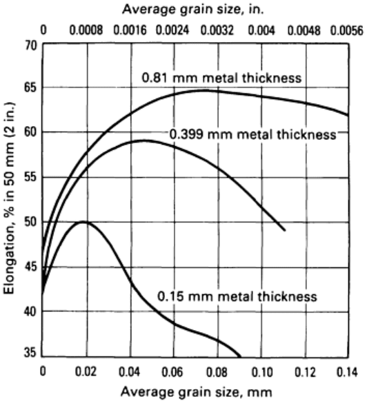
Fig. 17 Elongation versus grain size for Alloy C26000 sheets of various thicknesses. Source: Ref 3.
For optimal deep-drawing and stretch-forming properties, the grain size chosen should provide maximum elongation.
With reference to Fig. 17, peak elongation for 0.15 mm (0.006 in.) thick strip occurs at an average grain size of 0.020 mm
(0.008 in.). For 0.40 mm (0.0157 in.) thick brass, a range of 0.038 to 0.061 mm (0.0015 to 0.0024 in.) average grain size
would provide maximum drawability. For 0.81 mm (0.032 in.) thick material, a range of 0.060 to 0.090 mm (0.0024 to
0.0035 in.) average grain size would give optimal performance.
The surface finish required on the final part is an important consideration when selecting the grain size to be used. When
metal with a coarse grain size is drawn or stretch formed, the surface roughens and develops an appearance resembling
orange peel. Such a surface is more difficult and costly to polish and buff. Therefore, when a part requiring a buffed
surface is to be produced, much effort is expended in designing the tools and process to use brass with a fine grain size.
A classic example of this situation is the one-piece brass or bronze doorknob (Fig. 3a). Such useful and decorative articles
are made by the millions, and these types of shapes are difficult to produce on draw presses. These parts are usually
produced in transfer presses, and the process can include 15 to 20 operations with one intermediate anneal or partial
anneal. The Alloy C26000 or C22000 strip from which these parts are made is usually about 0.76 mm (0.030 in.) thick,
and the grain size is usually 0.020 to 0.035 mm (0.008 to 0.0014 in.) or 0.015 to 0.030 mm (0.0006 to 0.0012 in.) to
provide sufficient ductility for the part to be drawn without surface roughening.
Special Considerations (Ref 4). A common concern in all drawing operations is the formation of ears at the top of
the cup sidewall. Ears occur in preferred directions (usually 45 or 0 to 90°) relative to the strip-rolling direction. Earing
reflects the crystallographic texture of the strip. In part manufacture, ears must be trimmed; therefore, nonearing grades of
copper and copper alloy strip are preferred for drawn parts.
A common concern in all drawing operations is the formation of ears at the top of the cup sidewall. Ears occur in
preferred directions (usually 45 or 0 to 90°) relative to the strip-rolling direction. Earing reflects the crystallographic
texture of the strip. In part manufacture, ears must be trimmed; therefore, nonearing grades of copper and copper alloy
strip are preferred for drawn parts.

For copper alloys, the reduction in diameter in a single draw (cupping) usually ranges from 35 to 50%, with a 50%
reduction corresponding to ideal conditions. Drawing procedures vary widely in commercial practice. Reductions for
successive draws of the commonly formed brasses, under favorable operating conditions and without intermediate
annealing, are usually 45% for cupping; 25% for the first redraw; and 20, 16, 13, and 10% for subsequent redraws.
Greater reductions are usually obtained with blank thicknesses larger than about 1.62 mm (0.064 in.); for blank
thicknesses less than about 0.38 mm (0.015 in.), reductions are usually about 80% of the percentages given above. With
an annealing operation before each redraw, a reduction of 35 to 45% in each successive redraw can be obtained under
favorable operating conditions, assuming that the accompanying reduction in wall thickness is acceptable.
Die radius usually varies from about twenty times the metal thickness for material 0.127 mm (0.005 in.) thick to about
five times the metal thickness for material 3.18 mm (0.125 in.) thick. Radii of this size prevent high stress concentrations
at the die opening, which can lead to tearing in subsequent draws. Sharper radii are needed for flanged shells and for
meeting special design requirements.
The punch radius, except for the final stages of drawing, is usually less than one-third of the punch diameter, or four to
ten times the metal thickness. Clearance between punch and die is maintained at values that produce at least a slight
amount of ironing of the sidewalls.
References cited in this section
3.
J.H. Mendenhall, Ed., Understanding Copper Alloys, Olin Corporation, 1977
4.
"Advanced Sheet Metal Forming Cours
e," Metals Engineering Institute Home Study and Extension Course,
American Society for Metals, 1979
Forming of Copper and Copper Alloys
Frank Mandigo and Jack Crane, Olin Corporation
Coining
Nature of the Operation. Coining is a cold-forming process in which the work metal is compressed between two dies
so as to fill the depression of both dies in relief or to reduce the strip thickness. The most familiar coining operation is the
minting of coins. However, one of the most common uses of coining is in reducing the thickness or width of electrical and
electronic connectors and leadframe leads.
Materials Characteristics. The ability of a material to be coined is determined by its strength and work-hardening
rate. In general, copper, the lower-zinc brasses, the lower-alloy nickel silvers, and the copper nickels, which all exhibit
low work-hardening rates, exhibit good coinability (Fig. 15).
Forming of Copper and Copper Alloys
Frank Mandigo and Jack Crane, Olin Corporation
Spinning
Nature of the Operation. Spinning is a method of forming sheet metal or tubing into seamless hollow cylinders,
cones, hemispheres, or other circular shapes by a combination of rotation and force. Manual and power-automated
equipment is used for spinning copper alloys. More information is available in the article "Spinning" in this Volume.
