ASM Metals HandBook Vol. 14 - Forming and Forging
Подождите немного. Документ загружается.


Large irregular curves are obtained using stretch bending. The workpiece is gripped at the end, stretched, and bent as it is
stretched around a form. Usually, less springback occurs when the work is bent while it is stretched. The gripped ends are
customarily trimmed off. This method can accomplish in one operation what would otherwise take several operations.
The result is a possible savings in time and labor, even though stretch bending is a slow process. The tools, form blocks,
or dies for stretch bending are simpler in design and less costly than conventional press tooling. Stretch bending of bars is
described in more detail in the article "Stretch Forming" in this Volume.
Bending of Bars and Bar Sections
Bending Machines
The machines used for the bending of bars include the following: devices and fixtures for manual bending, press brakes,
conventional mechanical and hydraulic presses, horizontal bending machines, rotary benders, and bending presses.
Shapers have also been used to perform specific bending operations.
Manual Bending. Hand-powered machines or fixtures are used in many shops for making bends that do not require
much energy to form. This equipment is supplied with ratchets, levers, or gears to give the operator mechanical
advantage. Different types of fixtures are used for manual draw bending, stretch bending, or compression bending. Roll
bending is seldom done by hand. The tools used in manual bending are the same as those used on some power bending
machines. The maximum sizes of low-carbon steel bars that can be manually cold bent are given in Table 1.
Table 1 Maximum sizes of low-carbon steel bars for manual bending
Shape Size mm (in.)
Rounds 25 mm (1) (diam)
Squares
19 mm ( ) (per side)
Flats bent on flat
9.5 × 10² ( × 4)
Flats bent on edge
6.4 × 25 ( × 1)
Angles
4.8 × 25 × 25 ( × 1 × 1)
Channels
4.8 × 13 × 25 ( × × 1)
Press brakes are used for all types of bending, especially in small-lot production (25 to 500 pieces), when standard
tooling or low-cost special tooling can be used. Often, the punch is not bottomed in the die; but the stroke is controlled,
and the bar is bent "in air" (Fig. 4). With this technique, various bend angles can be made with the same die (see also the
article "Press-Brake Forming" in this Volume).
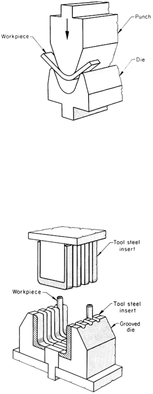
Fig. 4 Air bending of a bar in a press brake.
Mechanical presses are generally used only for mass production, because only large production lots can justify the
cost of tooling, which is more than that for most standard bending tools. Figure 5 shows a round bar being bent into a U-
bolt in a press. The bar is first cut to length and pointed at both ends (preliminary to a later threading operation). The bar
is then loaded into the press and held in a grooved die that bends the bar into a U in one stroke. In the setup shown in Fig.
5, more than one workpiece can be bent at a time. The following example describes an application of a mechanical press
in bending bars.
Fig. 5 Use of a grooved die in a mechanical press for bending a round bar into a U-bolt in one stroke.
Example 2: Bending a Welded Assembly in a Mechanical Press.
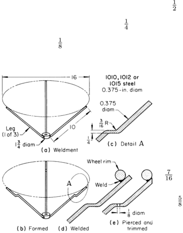
The wheel spider shown in Fig. 6 had three 254 mm (10 in.) long spokes of 9.52 mm (0.375 in.) diam low-carbon steel.
The spider was assembled by welding the three spokes to a 13 mm ( in.) thick steel hub. The assembly was loaded into
a 670 kN (75 tonf) mechanical press, a double bend (joggle) was made in the spokes, and the short straight surface
between the two bends was flattened to 6.4 mm ( in.) thick. The wheel rim was then welded to the spokes as shown in
Fig. 6(d). Next, the assembly was loaded into another press, in which the legs were sheared flush with the outer edge of
the rim and a 3.2 mm ( in.) diam hole was pierced in the flattened area of each spoke. The production rate was 25 per
minute.
Hydraulic presses are often used to bend bars in
much the same manner as mechanical presses. Although
hydraulic presses are usually slower than mechanical
presses, they have the advantage of exerting full force
over a long stroke. Therefore, deep bends can often be
made on a hydraulic press much smaller than the
mechanical press that would be required. In the
following example, a hydraulic press needed so little
head room that a closed shape could be bent over it.
Example 3: Bending a Double-Bar
Structure in a Hydraulic Press.
A double-bar structure was constructed of two 11 mm
( in.) diam bars that were connected by welded cross
members to form a ladderlike structure. A rectangular
shape was formed by making four 90° bends having 16
mm ( in.) inside radii. The two bars (sides of the
ladderlike structure) were bent simultaneously, using a
punch that forced the bars between rollers. By using a
small (27 kN, or 3 tonf) vertical hydraulic press, the four
bends could be made consecutively, allowing the
workpiece to encircle the press ram as bending was
completed. The overhead clearance would not have been
available with a mechanical press. This technique
permitted the fabrication of 360 double bends (90
frames) per hour.
Horizontal bending machines for bending bars consist of a horizontal bed with a powered crosshead that is driven
along the bed through connecting rods, crankshaft, clutch, and gear train. Dies are mounted on the bed, and forward
motion of the crosshead pushes the bar through the die. The long stroke and generous die space make this machine useful
for a variety of cold- and hot-bending operations, although speeds are lower than those for mechanical presses of similar
capacity. Horizontal benders are available in capacities from 89 to 2700 kN (10 to over 300 tonf).
Rotary benders, either vertical or horizontal, are used for the draw, compression, or stretch bending of bars. Such
machines consist of a rotary table in either a horizontal or vertical position on which the form block or die is mounted
(Fig. 1). Suitable hydraulic or mechanical clamping, tensioning, or compressing devices are provided to hold the
workpiece while the die rotates to the required position, or while the workpiece is bent about the central forming die.
Some machines can make bends by two, or all three, methods.
Bending presses are most widely used for bending tubing (see the article "Bending and Forming of Tubing" in this
Volume). However, bending presses are occasionally used for bending bars, as in the following example.
Example 4: Making a Double Crank in a Bending Press.
Fig. 6
Welded bar assembly that was formed by bending
in a mechanical press. Dimensions given in inches.
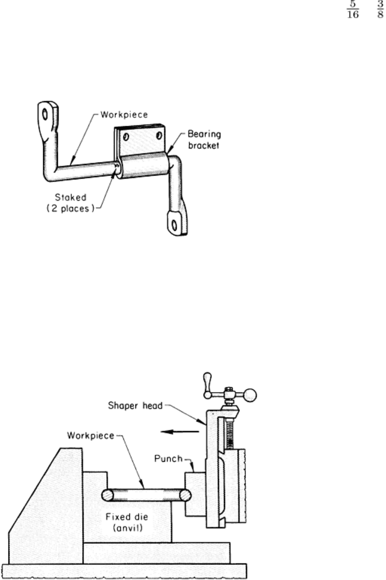
Double cranks such as the one shown in Fig. 7 were made in a bending press from round bars 7.9 or 9.5 mm ( or in.)
in diameter. The bars were cut to length and fed into the press to flatten the ends and pierce the holes. The two sharp
bends were made one at a time in the same press with a V-die. A bearing bracket was assembled on the crank, followed
by a double-staking operation in the same press. The greatest demand on the press was in the end-flattening operation,
which required a press capacity of 8900 to 13,300 kN (100 to 150 tonf).
Fig. 7 Double crank produced in a bending press.
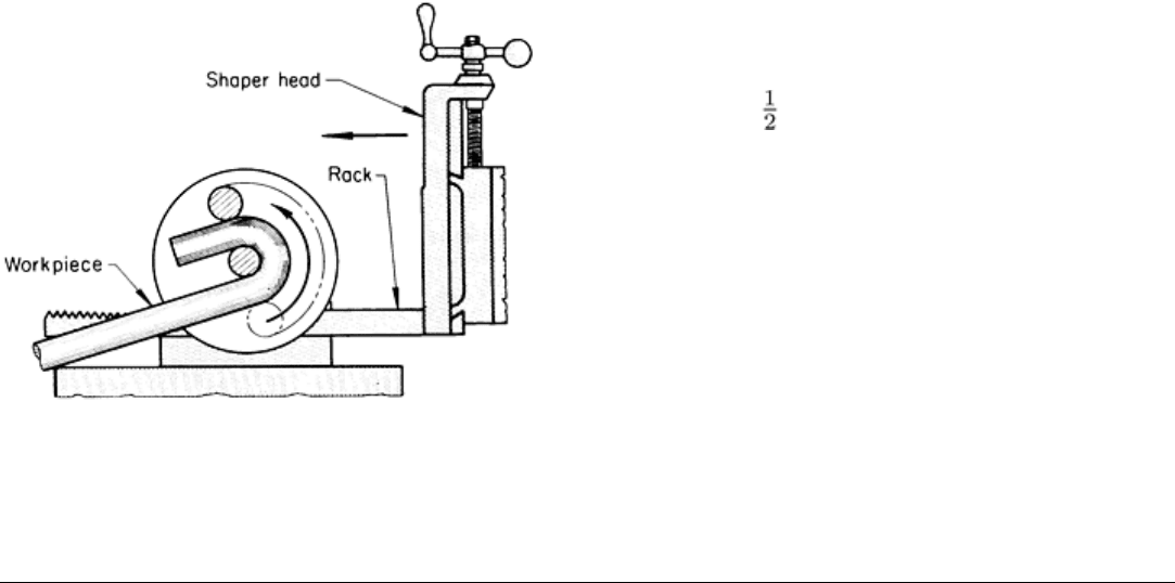
Shapers can be tooled for bending operations. One method is to have the fixed die, or anvil, held on the knee of the
shaper and the punch mounted on the ram (Fig. 8). The shaper must make one stroke only. The stroke can be adjusted to
allow for springback in the workpiece; therefore, the workpiece can be bent to fairly close limits.
Fig. 8 Use of a shaper for correction of springback in U-bolts, J-bolts, or rings.
The setup shown in Fig. 8 is used to correct for springback in formed parts such as J-bolts, U-bolts, and rings. A V-punch
and die mounted in the shaper can make bends of various kinds.
A shaper can also be provided with a rack and pinion to produce rotary motion for bending (Fig. 9). Bend radius can be
varied by the use of center pins of different diameters. A typical use of a shaper in the bending of bars is described in the
following example.
Example 5: Shaper Versus Press for the
Bending of J-bolts.
Originally, J-bolts were press bent cold in a die from sheared
lengths of 13 mm ( in.) diam hot-rolled merchant bars of
1025 steel. The press made the J-bolts by bending the bar into a
half circle with one long arm. Because the unbalanced support
caused variations in bending, some of the parts were
unacceptable.
The job was put on a shaper. For this operation, the stock was
sheared to double lengths, which the shaper bent into a circular
loop with two long arms (the ends). The looped bar was then
sheared in half. The cost of tooling for the shaper was much less
than that for the press.
A rack-and-pinion-actuated fixture similar to that shown in Fig.
9 was used to bend the bar into a circular loop. The bar stock
was placed in the fixture at a slight angle to allow one leg to
pass the other during forming. After the bar was cut in two, the J-bolt was finished in a setup such as that shown in Fig. 8.
Bending of Bars and Bar Sections
Tools
Tools for draw and compression bending are shown in Fig. 1. The form used in both processes is shaped to the contour of
the bend. It is usually grooved to fit the work. Often, the form is part of a right cylinder whose straight portion
(frequently, an insert) provides the surface against which the work is clamped. Hydraulic or mechanical pressure holds the
clamp against the workpiece. Annular grooves or roughened surfaces grip the bar or bar section.
To allow for springback, the bend radius is made smaller on the form than is required for the workpiece. The form is also
designed for a greater angle of bend than is needed. These two adjustments permit overbending the piece to allow for
springback. Such adjustments are made by trial and error. The form is tested and corrections are made before it is heat
treated.
The finish on the form (rotating or fixed) should be just good enough to avoid marring the workpiece. For most bar
bending, a machined finish is sufficient. For decorative stainless steel and polished aluminum, grinding or polishing of the
form surfaces may be needed. However, the clamping area should not be ground or polished unless necessary. The
smoother the finish in the clamping area, the greater the danger that the workpiece will slip through the clamp. The
pressure die and wiper shoe require a good finish (usually ground) because the work metal must slide along them.
When air bending bars in a press brake, simple V-blocks will suffice for the female dies. The opening of the V-blocks
should be eight times stock thickness for standard sections, and ten times stock thickness for heavy sections. The upper
die (punch) is shaped to the inside radius of the bend, and the angle of bend is controlled by the length of stroke. The
same die set can be used for making various bends, as well as for various stock thicknesses, by adjusting the stroke.
Press brakes can use rubber pads for tooling on bends that need support (see the article "Press-Brake Forming" in this
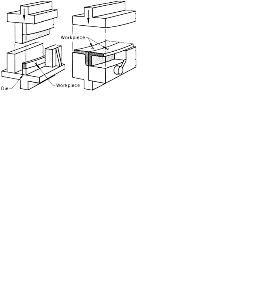
Volume). Completely shaped dies for bottoming can also be used in a press brake, as shown in Fig. 10.
Fig. 9 Bending with rotary motion in a shaper.
Most dies used in conventional mechanical or hydraulic
presses are completely shaped bottoming dies, which
makes them more expensive than tooling for other
bending machines. Tooling for bending presses is
specially designed to fit the needs of the machine and the
work to be done. Dies for bending presses are simple to
construct and relatively inexpensive. Tools for stretch
bending are covered in the article "Stretch Forming" in
this Volume.
Die Materials. Dies are usually made of hardened steel
for the production of thousands of pieces per month.
Tool steel is used for small one-piece dies. Larger dies
are made of low-carbon steel and then carburized and
hardened. Clamping inserts are made separately.
For moderate production of a few hundred pieces per
month, unhardened carbon steel is often used. If only a
few parts are needed, wood or an aluminum alloy may
be strong enough for dies.
For bottoming dies in presses, hardened tool steel is always used. For cold bending, A2 tool steel hardened to 58 to 62
HRC is most often selected. A hot-work tool steel, such as H11, hardened to 45 to 50 HRC is usually the choice for hot
bending.
Bending of Bars and Bar Sections
Bend Allowance
The stock consumed in a bend (that is, overall length of a bend) can be computed from the radius of curvature at the
neutral axis and from the angle of the bend. A formula often used for this computation is:
W = 0.01745 α(r + δ)
where W is the bend allowance, α is the angle of bend (in degrees), r is the radius of bend to inner stock surface, and δ is
the distance from the inner surface to the neutral layer (a commonly used approximation when this figure is not known is
one-third to one-half stock thickness). The constant 0.01745 is a conversion factor changing degrees to radians.
When bar stock for a workpiece whose ends are within, or very near, the bend area is cut square to the neutral axis, the
ends, after forming, will not be square to the neutral axis. The basic reason for this is the difference in circumference of
the outer and the inner surfaces of the bend. Additional deviation from squareness can be expected because all of the
material toward the outside of the bend from the neutral axis has undergone a tensile load and the material inside this line
has been under compressive load. Unless compensation can be made for these variations, the ends of the formed part must
be trimmed if they are to be square to the axis. However, when end details, locating surfaces, and other considerations
necessitate such action, it is still possible to cut the blanks to size in such a way that trimming after forming is eliminated.
Bending of Bars and Bar Sections
Lubrication
Successful bending depends to a large extent on the type of lubricant used. No one lubricant works equally well on all
materials. Selection of a lubricant varies among different shops. Typical lubricants for bending specific metals are listed
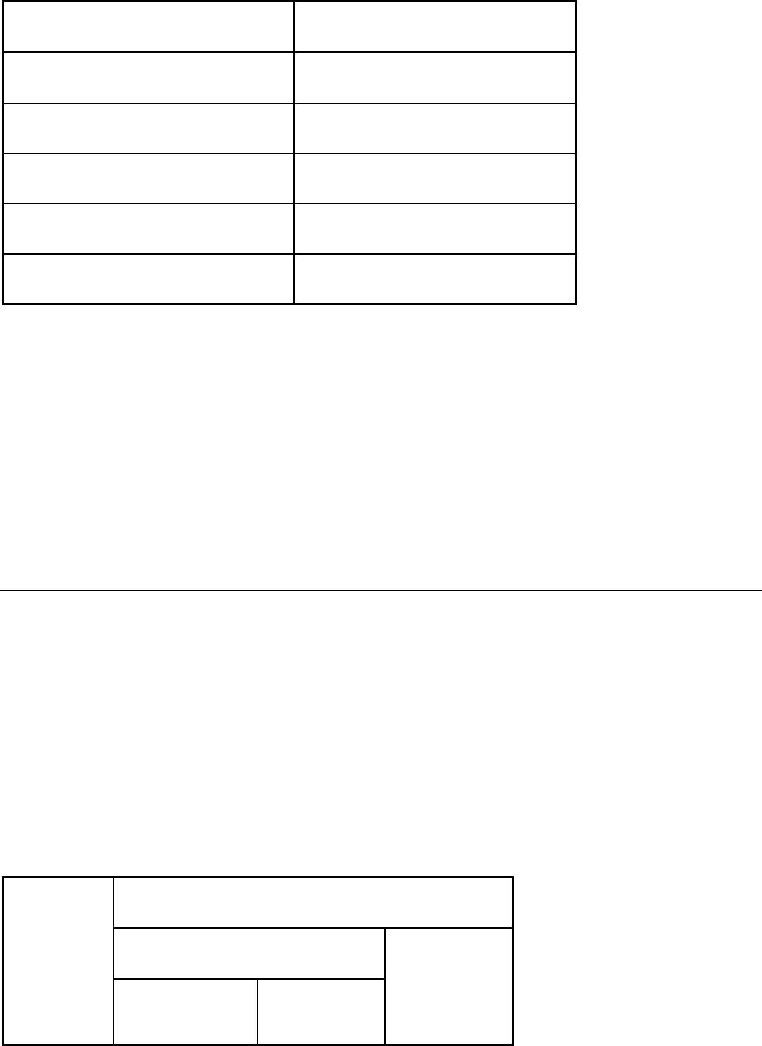
in Table 2.
Table 2 Typical lubricants for bending various metals
Fig. 10
Die setups in a press brake for edge bending a
bar (left) and for bending two structural angles (right).
Work metal
Lubricant
Low-carbon steel
Water-soluble, vegetable-oil base drawing oil
(a)
Stainless steel and other high-alloy iron-base alloys
Mineral-oil-base drawing oil
(a)
Aluminum alloys and copper alloys
Mineral oil
Brass (severe bends)
Soap solution
(b)
Hot bending of carbon, alloy, and stainless steels
Molybdenum disulfide
(a)
Available as proprietary material.
(b)
Creamy mixture of laundry soap and water
Overlubrication, in either quantity or type of lubricant, must be avoided. Not only is excessive lubrication likely to cause
wrinkling, but the cost of removal must be considered. It is never good practice to use a pigmented compound if
successful results can be obtained with an unpigmented compound, because pigmented compounds are more difficult to
remove.
Wiper dies are lubricated with a very small quantity of high-grade drawing lubricant. It is important not to overlubricate
pressure dies and wiper shoes.
Bending and Forming of Tubing
Introduction
THE PRINCIPLES for bending tubing are much the same as those for bending bars (see the article "Bending of Bars and
Bar Sections" in this Volume). Two important additional features in the bending of tubes are that internal support is often
needed and that support is sometimes needed on the inner side of a tube bend.
The wall thickness of the tubing affects the distribution of tensile and compressive stresses in bending. A thick-wall tube
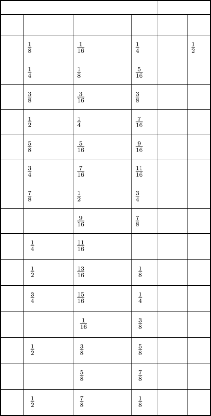
will usually bend more readily to a small radius than a thin-wall tube. Table 1 lists the minimum practical inside radii for
the cold draw bending of round steel or copper tubing, with and without various supports against flattening and wrinkling.
Table 1 Minimum practical inside radii for the cold draw bending of annealed steel or copper round tubing
to 180°
Radii can be slightly less for a 90° bend, but must be slightly larger for 360°.
Minimum practical inside radius
Grooved bending tools
Tubing
outside diameter
With mandrel; ratio,
<15
(a)
(best conditions)
With mandrel or
filler; ratio, <50
(a)
Cylindrical bending
block without
mandrel; ratio, <30
(a)
(poor conditions)
(normal conditions)
mm in. mm in. mm in. mm
in.
3.2
1.6
6.4
13
6.4
3.2
7.9
25
1
9.5
4.8
9.5
50
2
12
6.4
11
75
3
16
7.9
14
102
4
19
11
17
152
6
22
13
19
203
8
25 1 14
22
254
10
32
1
17
25 1 381
15
38
1
21
29
1
508
20
44
1
24
32
1
686
27
50 2 27
1
35
1
889
35
64
2
35
1
41
1
. . .
. . .
75 3 41
1
48
1
. . .
. . .
89
3
48
1
54
2
. . .
. . .

102 4 54
2
60
2
. . . . . .
(a)
Ratio of outside diameter to wall thickness of tubing
Bending and Forming of Tubing
Selection of Bending Method
The four most common methods of bending tubing are basically the same as those used in the bending of bars:
compression bending, stretch bending, draw bending, and roll bending. The method selected for a particular application
depends on the equipment available, the number of parts required, the size and wall thickness of the tubing, the work
metal, the bend radius, the number of bends in the workpiece, the accuracy required, and the amount of flattening that can
be tolerated.
Hand Versus Power Bending. The bending methods and tooling used in hand bending are the same as those for
power bending. Steel tubing as large as 38.1 mm (1.50 in.) in outside diameter with a 1.65 mm (0.065 in.) wall thickness
can be bent by hand, but the process is slow and repeatability is questionable. Some hand benders use an adjustable
friction device, a kind of sliding brake, to prevent sliding of the tubing. The friction prevents wrinkles and other defects in
bending. The following two examples illustrate several of the factors that must be taken into consideration in selecting
either hand bending or power bending to fabricate tubing.
Example 1: Hand Bending of a U-Shaped Furniture Part Having Two 90° Bends.
Bending equipment was needed to produce a U-shaped furniture part with two 90° bends from 19 mm ( in.) outside
diameter 1010 steel welded tubing with a 1.25 mm (0.049 in.) wall thickness. The two bends were made to a 50 mm (2
in.) radius as measured on the tube centerline. A small amount of flattening was tolerated. Production rate was 500 pieces
per month.
Because no great accuracy was needed and because the production volume did not warrant more than a minimum
investment, a bending fixture for compression bending by hand was selected, along with tooling to allow for both bends
to be made in one setup. If production volume had been larger, a power-driven bender or a bending press might have been
selected.
Example 2: Power Bending of Machine Tool Hydraulic Lines.
In the production of hydraulic lines for machine tools, from 9.5 mm and 13 mm ( and in.) OD steel tubing and from
6.4 mm ( in.) OD copper tubing, hand bending required 6400 manhours per year for 44,000 bends. A change to power
bending reduced the man-hours needed to 450.
Bending and Forming of Tubing
Tools
Tools used for the bending of tubes are similar to those for the bending of bars (see the article "Bending of Bars and Bar
Sections" in this Volume). One important difference is that tools for tubes need carefully shaped guide grooves to support
the side-walls and to preserve the cross section during the bend.
Form blocks, or bending dies, resemble those described in the article "Bending of Bars and Bar Sections" in this
Volume. They either rotate or are fixed, depending on the arrangement of the machine in which they are used. One end of
the tube is clamped at the end of the groove in the form block, and the tube is bent by being forced around the block and

into the groove. For round tubes, the depth of the groove in the form block should be one-half the outside diameter of the
tube to provide sufficient sidewall support.
The block becomes the template for holding the shape of the bend. Form blocks can be made of wood, plastic, or
hardboard; if they are to be used for an extensive production run, they can be made of tool steel and hardened.
Clamping blocks hold the end of the tube to the form block and maintain the holding force necessary to make the
bending action effective. Although the groove in the clamping block should be well formed, the finish should not be so
fine that the tube will slip. Ordinarily, the as-machined finish is adequate, but sometimes ridges or serrations are
machined into the clamp to increase the holding force. Rosin can be applied to the tube to prevent it from slipping in the
clamp.
If the clamped area is to be part of the finished piece, care must be taken to prevent scratches or mars. If the clamping
groove has to be ground or polished to provide a good surface, the portion of the tube to be clamped will have to be
longer to distribute the higher clamping force better. When the clamping length is short, the end of the tube is sometimes
plugged to prevent it from deforming from high clamping forces. Table 2 lists typical clamping lengths for bending steel
tubing.
Table 2 Typical clamping lengths for bending steel tubing
Radius
of bend
centerline
Wall thickness
of tube, mm (in.)
Typical length
clamped
<0.89 (0.035)
4-5 × OD
0.89-1.65 (0.035-0.065)
3-4 × OD
1 × OD
>1.65 (0.065)
2-3 × OD
<0.89 (0.035)
3-4 × OD
0.89-1.65 (0.035-0.065)
2-3 × OD
2 × OD
>1.65 (0.065)
1 -2 × OD
3 × OD <1.65 (0.065)
2-3 × OD
Pressure dies are used in the draw bending of tubing to press the workpiece into the groove in the form block and to
support the outer half of the tube. The most commonly used pressure die is as long as the developed length of the bend
plus some allowance for holding, and it does not slide over the tube but travels with it as it moves toward the bend area
(see the article "Bending of Bars and Bar Sections" in this Volume). In one face, it has a groove with a depth that is
slightly less than one-half the outside diameter of the tube.
A stationary pressure die or even a roller can be used on noncritical work. Either unit has a tube-forming groove
machined in its face. Most stationary pressure dies are made of low-carbon steel, which can be case hardened to resist
wear. Tool steel such as O1, A2, or D2, hardened to 55 to 60 HRC, or aluminum bronze is commonly used for sliding
dies.
