ASM Metals HandBook Vol. 14 - Forming and Forging
Подождите немного. Документ загружается.

The process was initially developed for riveting the 747 aircraft wing panels, which were too large to fit on an automatic
hydraulic riveting machine. The process proved so successful that a computer-controlled tool was developed to
incorporate EMR into the 767 aircraft wing spar assembly.
The EMR process is considered generally adaptable to any structural design in which fluid-tight, fatigue-critical, or large-
diameter fasteners are required. The EMR system has been mounted on a robot for automated assembly of automotive
components.
Electromagnetic Welding. The EMF concept has been expanded to encompass impact welding, in addition to
forming and mechanical joining. This refinement is referred to as pulsed magnetic (PM) welding and is in use in the
manufacture of nuclear fuel pins.
High-frequency high-intensity pulsed magnetic fields are being used to produce fuel pin end closures on cladding of
interest to a breeder reactor program. Solid-state welds between the fuel pin cladding and a tapered end plug insert are
produced by a pulsed magnetic field that accelerates and collapses the cladding, causing it to exert high-velocity impact
on the end plug insert.
The field is produced when capacitively stored energy is switched into a single-turn work coil. The resulting high velocity
of the cladding produces an impact bond. The peak magnetic field is in the range of 50 T (500,000 gauss), which
translates into pressures in excess of 689 MPa (100 ksi). These pressure loadings accelerate the cladding radially inward.
Collapse velocities of 304.8 m/s 1000 ft/s have been measured.
The end plug design is an important parameter in the welding process. The insert is tapered to allow the impact region to
self-clean and to relieve itself of the stress waves created by the impact. As the impact point moves along the tapered
surface, the high-velocity impact causes plastic deformation at the region of impact. At the high strain rates that occur at
impact, the cladding and end plug material behave like high-viscosity fluids. The result is that a small surface layer is
ejected. This self-cleaning action results in an atomically clean surface, and welding is accomplished without going to a
melt temperature. Bonds have routinely been observed with lengths five to ten times the cladding wall thickness.
Most of the work has been performed on type 316 stainless steel fuel pin cladding that was 20% cold worked with a 5.84
mm (0.230 in.) outside diameter and a 0.38 mm (0.015 in.) wall thickness. Other cladding materials were welded using
identical conditions. These included Inconel 706, Nimonic PE 16, and RA 330, which were in the solution-annealed
condition.
Combinations of Operations. Some parts that would require a number of separate conventional forming operations
can be made in a single operation by EMF. For instance, simple tooling can be devised to combine blanking, piercing, or
other cutting operations, and accomplish complex forming in one step. In the example that follows, a simple die was
made to pierce two holes in an aluminum alloy tube, expand the tube, and form a 180° flange on one end of the tube, all
in one EMF operation.
Example 2: One-Operation Forming and Piercing by EMF.
The tubular part shown at the right in Fig. 11 was produced in one EMF operation by using an expansion coil to form,
flange, and pierce a length of tubing against a single-piece die (setup shown at the left and center in Fig. 11). The
workpiece was a 100 mm (4 in.) length of aluminum alloy 6061-O tubing with an 83 mm (3¼ in.) outside diameter, 0.89
mm (0.035 in.) thick wall, and a yield strength of 50 MPa (7 ksi).
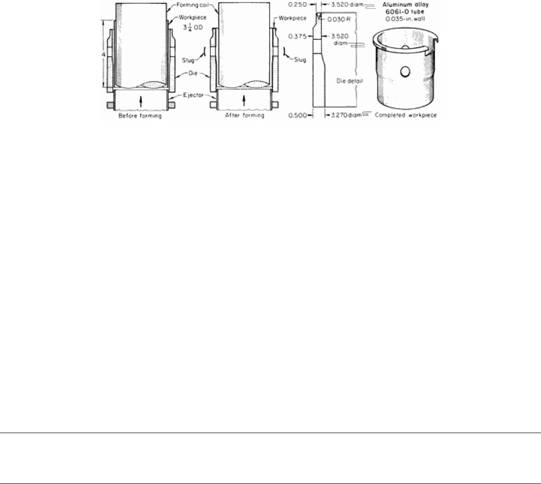
Fig. 11 Forming and piercing a tubular part in one operation. Dimensions given in inches.
The die was turned from 4340 steel tubing with a 12.7 mm (½ in.) thick wall, and two holes were drilled in the die to
accomplish the piercing operation. The formed part was removed from the die by means of a simple ejector. The forming
equipment had a capacity of 6 kJ (4400 ft · lbf), and cost approximately $18,000. The production rate was 240 pieces per
hour, using manual loading and unloading.
Plastics, Composites, Rubber, and Ceramics. The material onto which a workpiece is formed is not a significant
factor in the process except that it must be strong enough to withstand the impact of the workpiece. Therefore, assemblies
using metal parts formed onto plastics, composites, rubber, and ceramics are common.
Automotive components such as electric fuel pumps, gasoline fill tubes, cruise control power units, and emission control
devices use aluminum, usually anodized, over plastics. Wall thicknesses of 0.50 to 1.3 mm (0.020 to 0.050 in.) are
assembled over plastics that include Delrin 100, glass-filled polyester, and polycarbonate. Fiberglass, carbon fiber, and
other composite materials are joined with aluminum, copper, and brass in applications ranging from high-voltage fuses to
drive shafts for trucks.
Banding of rubber boots on shock absorbers, CV joints, and the like was among the earliest applications. Surge arrestors,
insulators, and other ceramic devices are assembled by EMF. Its potential application with new types of ceramics has not
been fully explored.
Electromagnetic Forming
Revised by Michael M. Plum, Maxwell Laboratories, Inc.
Safety
The potential hazards of EMF operations may be categorized as either mechanical and sonic or electrical hazards.
Mechanical and Sonic Hazards. Electromagnetic forming equipment can cause substantial damage if its forces are
misdirected, as would be expected of any equipment that exerts high pressure and delivers energy at a high rate. The
magnetic pulse produces pressure perpendicular to the surface exposed to the field. Thus, if a cylindrical workpiece is
positioned in such a way as to pass completely through a compression coil, only radial forces will be exerted on it during
the forming operation. If, however, such a workpiece were inadvertently inserted only partly through the coil, the force
produced by the magnetic pulse on the end could be sufficient to eject the workpiece from the coil at high velocity. In the
same way, improperly positioned parts could be ejected from an expansion coil. An appropriate coil shield should be
provided to protect personnel. Proper fixturing must be used to ensure that the machine will operate safely.
The sound produced in EMF operations results from the rapid movement of the workpiece compressing the air, and
ordinarily is at a moderate level. If, however, the area of the workpiece that is moved in the air is large, and the distance
moved is great, additional sound conditioning may be required. Production units are designed to comply with
Occupational Safety and Health Administration (OSHA) requirements.

The possibility of an electrical arc in a coil or field shaper is a remote potential source of mechanical or sonic hazard. In
the unlikely event of an electrical insulation failure, essentially all of the energy in the capacitor bank may be directed into
an arc, generating high-intensity sound and perhaps forcibly ejecting bits of insulation or metal. A shield should be placed
between the operator and the work coil to protect personnel. Protection against the sonic hazard depends on the distance
between the operator and the coil. Care should be taken to prevent metallic chips from falling onto exposed parts of the
field shaper gaps, where they could produce an arc-over. Insulators should be regularly checked for wear and cracks.
Electrical Hazards. Voltages used in typical EMF operations range up to 10 kV, and the capacitor banks can deliver
extremely high current. Furthermore, voltages up to 50 kV are used for special applications, such as impact welding. All
high-voltage components of the system are completely contained in a well-grounded heavy-gage metal cabinet. Doors and
panels are electrically interlocked to avoid unauthorized access to high-voltage components. Maintenance personnel
should work on energy-storage circuitry only after shorting the storage capacitors according to manufacturer's
instructions. Maintenance personnel should also observe all standard precautions when working with the high-voltage
components of the machine.
Pulsed voltages of the type that appear at the coil terminals of EMF equipment are much less dangerous than direct
voltage. Normally, pulses of no more than 1000 V appear in any exposed portion of the equipment. The typical 10 kHz
pulse appears for less than 1 μs. Nonetheless, precautions should be taken to prevent operators from being directly
exposed to such voltages. The workpiece should never be held by hand because the possibility always exists that an arc-
over between coil and workpiece could occur.
Coils are encased in metal shells that act as eddy current shields. As a result, the magnetic field is reduced to a very low
level at any distance beyond the coil. Although the potential dangers may seem obvious, all personnel should be warned
against touching or holding a coil, field shaper, or workpiece during the forming operation.
Electromagnetic Forming
Revised by Michael M. Plum, Maxwell Laboratories, Inc.
Equipment
The basic pieces of equipment in an EMF system are the capacitor bank, the coil, and the field shaper.
Capacitor banks are the energy-storage devices used for EMF. To charge the capacitor bank, alternating current is
converted to high-voltage direct current by a suitable power supply or charging circuit. The charging rate must be fast
enough to charge the capacitor bank in an interval not less than the desired repetition rate for the pulse discharge. For
maximum energy transfer to the coil during the impulse, internal resistance and inductance in the power supply must be
kept to a minimum.
Standard commercial EMF machines have capacitor bank energy sources rated from 8 to 200 kJ (5900 to 147,500 ft · lbf).
Units with a capacity greater than 16 kJ (11,800 ft · lbf) are designed on a modular basis with increments of 4 kJ (3000 ft ·
lbf).
Because production rates with manual loading and unloading are generally about 200 to 600 pieces per hour, machines for
this type of operation are designed for pulse repetition rates in this range. The faster pulse repetition rate desired for use
with automatic work-handling equipment is readily obtained, however, as it is limited only by the characteristics of the
charging circuit and the rate at which the components of the system dissipate heat.
Commonly available machines use capacitor banks rated at 8 to 16 kJ (5900 to 11,800 ft · lbf). Each capacitor is switched
into a parallel-plate bus (or low-inductance coaxial cable) system through individual molybdenum anode ignitrons
specially designed for pulse service. The capacitors are charged through a constant-current rectifier system.
The energy stored in the bank is precisely measured by a voltage-metering circuit. When the preset energy level is
reached, the charging cycle is terminated and the switches (ignitrons) are triggered, either automatically or by an outside
pulse, to discharge the capacitors into the forming coil. The storage systems are designed to have very low internal
inductance, so that maximum energy is transferred to the forming coil during the impulse.
The maintenance of control circuits and charging circuits using solid-state components is comparable to that required in
other industrial equipment of moderate to low complexity. The average life of a capacitor at a cycling rate of 600
operations per hour at maximum energy is about 3 million operations. At reduced energy levels, capacitor life is much
longer.
Coils and Field Shapers. The three primary factors in the design of coils and field shapers are electrical
characteristics, size, and strength. The theory of their design is extremely complex, and material and construction
requirements are highly critical, because forming coils must accept the repetitive discharge of large amounts of electrical
energy in pulses lasting only 10 to 100 μs and must generate uniform forming pressures as high as 340 MPa (50 ksi).
Using interchangeable field shapers with standard coils in compression operations promotes convenience, versatility, and
economy. For long production runs, coils with fixed field shapers provide greater efficiency and durability. A variety of
coils of standardized designs are available. Depending on the type and the application, coils can provide from a few
hundred thousand to several million operations before repair or replacement is required.
In terms of size, the diameter of the section in the workpiece to be formed determines the diameter of the working surface
of the field shaper, or of the coil when a shaper is not used. A clearance of about 1.3 mm (0.050 in.) per side is ordinarily
needed for insulation and work insertion and removal. For maximum efficiency, the clearance is kept as small as possible
because the effective force varies inversely with the square of the clearance distance.
In respect to strength, coils are usually of multiturn design, with sufficient mass to withstand repeated forming impacts.
The coil not only must be strong enough to sustain these repeated thrusts, but also must be massive and rigid enough to
minimize its deflection under load.
The problem of building coils to withstand high load is distinctly different in each of the three basic types of coils.
Because there are no stringent volume restrictions on compression coils, they can be strong and massive, regardless of the
size of the workpiece.
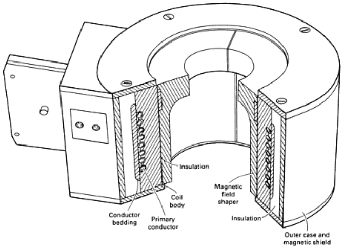
The coil receives support from a metallic coil body (usually of beryllium copper) and an insulating structure (see Fig. 12
and 13), which are needed for safe and efficient handling and for the efficient use of electrical energy.
Fig. 12 Sectioned view of magnetic compression coil with removable magnetic field shaper.
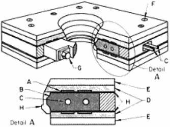
Fig. 13 Heavy duty wafer-
type compression forming coil. A, primary conductor; B, beryllium copper field
shaper; C, water passage; D, fiberglass insulation; E, steel backup plates; F, press bolt; G, shaper press bolt;
H, shaper insulation.
Expansion coils must fit inside the workpiece, and thus the space to provide a strong structure is restricted. In small-
diameter coils, shown in Fig. 3(b), the conductors must be relatively small in cross section to allow space for the return
flux, and the conductors must be supported by an insulating mandrel. The force that can be exerted by these coils is
ultimately limited by the strength of the mandrel. Production coils are typically 50 mm (2 in.) in diameter or greater.
Some flat spiral coils, shown in Fig. 3(c), also depend on the strength of an insulating backing to give the conductors
support, so that the peak force they can exert depends mainly on the strength of the support. Other contour-forming coils
have been made with massive construction; these have the same load limitations as do compression coils.
General-Purpose Compression Coil. Figure 12 shows a type of compression coil designed for ruggedness and
versatility in applications on tubular parts up to 230 mm (9 in.) in diameter. Standard coils have inside diameters of 100,
150, or 250 mm (4, 6, or 10 in.) and have interchangeable field shapers of beryllium copper, each designed for a specific
workpiece.
The flux concentration at the inner wall of the field shaper causes it to heat faster than the rest of the assembly. It is
cooled by convection or by forced air circulation. In high-speed coils, the field shaper is sometimes water cooled. Heat
generated in the coil body and primary conductor is removed by water circulating in the copper tubing of the primary
conductor.
Heavy-Duty Compression Coils. Even stronger, more efficient construction is found in a heavy-duty single-turn coil
and in the wafer-type coil shown in Fig. 13, for which the forming pressure is limited only by the properties of the shaper
material. Wafer coils are used in energy ratings up to 60 kJ (44,300 ft · lbf) and pressure ratings up to 340 MPa (50 ksi).
Expansion Coil. Light-duty expansion coils, for use at pressures up to about 50 MPa (7 ksi), consist of solenoid coils of
beryllium copper tubing wound on fiberglass forms. They are commonly up to 250 mm (10 in.) in active length and 100
mm (4 in.) in diameter, and are usually designed for the forming of specific workpieces. Coils that are 0.60 m (2 ft) long
or more than 2 m (6 ft) in diameter have been built and applied successfully in the aerospace industry.
In the following example, a deep contour was formed in a hoop-shaped part by impact against a ring die, using an
expansion coil.
Example 3: Electromagnetic Forming of a Grooved Hoop-Shaped Part.
As shown in Fig. 14, a grooved hoop-shaped part was formed by expanding a welded blank of 0.75 mm (0.030 in.) thick
steel into a ring die, without using a field shaper. The weld bead was ground smooth before forming. Because of the high
velocity of the blank when it struck the die, it conformed accurately to the die contour. About 40 kJ (3000 ft · lbf) of
energy was used. The 4340 ring die (Fig. 14) was made by rolling, welding on lugs, bolting into a hoop shape, and then
turning the inside contour in a lathe. Because the die was not subjected to static pressure, there was no need for the sturdy
construction that would have been necessary had other forming methods been used. Using the EMF technique, it was
merely necessary that the die be many times more massive than the workpiece.
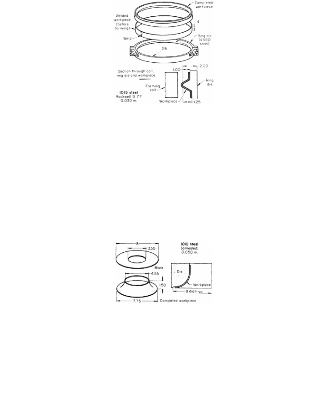
Fig. 14 Grooved hoop-shaped part. Dimensions given in inches.
Flat Spiral Coil. For contour forming of flat blanks, flat spiral coils apply essentially uniform pressure over a circular
flat area, except for a small area in the center. It is difficult to achieve durability at peak pressures above 35 MPa (5 ksi) in
such coils. The design of a flat spiral coil depends greatly on the requirements of the application. The electromagnetic
forming of a contoured part from flat stock, using a flat spiral coil, is described in the example that follows.
Example 4: Electromagnetic Contour Forming of an Orifice From a Flat Blank.
The fluid flow constrictor shown in Fig. 15 was formed by the use of a flat coil in a setup like that shown in Fig. 3(c). The
annealed 1010 steel blank, a flat annular disk with a 200 mm (8 in.) diameter, was laid on the coil under the die. The
magnetic field generated pressure against the disk, driving it against the die.
Fig. 15 Contoured part made from a flat blank by EMF. Dimensions given in inches.
The forming equipment had a rating of 12 kJ (8900 ft · lbf). An output of 10 kJ (7400 ft · lbf) was used in forming the
orifice. The production rate was 240 pieces per hour. Because of its use as a flow constrictor, the 115 mm (4.55 in.)
orifice diameter was accurately held. It was maintained without any trimming after forming. In cross section, the formed
part had an exponentially curved contour.
Electromagnetic Forming
Revised by Michael M. Plum, Maxwell Laboratories, Inc.
Electrical Principles
Because of the short duration of the magnetic impulse in EMF, the pressure must be high enough to impart sufficient
kinetic energy to the workpiece during the pulse to do the desired forming. Any resistance to the motion of the workpiece
during the impulse reduces the amount of useful forming energy transferred. Accordingly, for high efficiency, the peak
pressure should be several times that necessary to exceed the static yield strength of the workpiece and to overcome any
other constraints for the duration of the impulse.
Pressure Waveform. Electrically, a forming coil is an inductor, along with a small amount of series resistance. When
an energy storage capacitor is discharged through such a coil, the discharge is a momentary oscillating current. The
frequency of this oscillation is often called the ringing frequency by electrical engineers. This oscillating current has a
damped sine waveform. The frequency is inversely proportional to the square root of the product of the capacitance of the
storage bank and the inductance of the coil. The rate of decrease of the amplitude of the pulse is proportional to the
resistance of the coil circuit. The pressure produced by the coil is proportional to the square of this current; thus, the
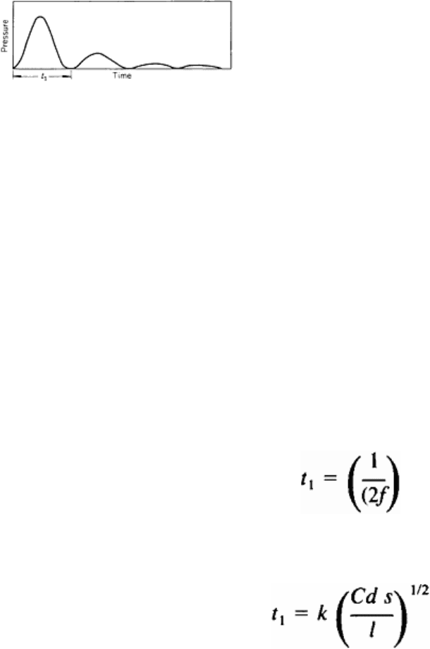
pressure pulse is essentially positive and approximates a damped sine square form, as illustrated in Fig. 16.
Virtually all of the forming energy is provided by the first wave;
succeeding waves transmit less energy to the workpiece because of their
lower energy content and because of the progressively widening gap
between coil and workpiece as forming takes place. The portion of the
energy of the electrical discharge that is not transferred to the workpiece
as kinetic, or deformation, energy appears as resistance heating.
An energy discharge, or pulse, can be characterized by its peak pressure,
which is that of the first wave, and by the duration of the first wave (Fig.
16). The time between successive waves changes slightly as the
workpiece moves (changing the inductance of the coil) and as heating changes the resistance of the electrical circuit.
However, these effects are ordinarily negligible.
Peak pressure is approximately related to other process variables. It is:
• Directly proportional to the energy of the electrical impulse from the capacitor bank
• Inversely proportional to the resistivity of workpiece and coil
•
Inversely proportional to the total of the volume of the workpiece and the field shaper penetrated by the
electromagnetic field (skin effect) and the volume between the coil and workpiece surfaces
The effect of workpiece size and electrical resistivity on peak pressure is discussed in the section "Typical Energy
Relations" below. Wave duration for the first wave in a pressure pulse in the idealized situation is inversely proportional
to the ringing frequency of the system:
Also, to a close approximation:
where k is a proportionality constant, C is the capacitance of the energy storage bank, d is the diameter of the workpiece
(for the surface adjacent to the coil), l is the working length of the workpiece (width of coil), and s is the thickness of the
flux pattern between coil and workpiece (including skin depth of workpiece and field shaper). Thus, the wave duration
increases with increasing capacitance of energy bank, diameter of workpiece nearest the coil, and spacing between coil
and workpiece, but decreases with increasing length of workpiece. The skin depth in workpiece and field shaper increases
with the increasing wave duration.
Fig. 16 Typical pressure waveform in EMF.
Electromagnetic Forming
Revised by Michael M. Plum, Maxwell Laboratories, Inc.
Typical Energy Relations
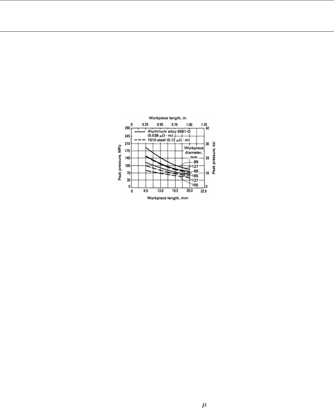
The actual energy relations in the forming of aluminum alloy 6061-O, with a resistivity of 0.038 μΩ· m, and low-carbon
steel, with a resistivity of 0.12 μΩ· m, are shown in Fig. 17. The data were obtained using a 12 kJ (8900 ft · lbf) machine
operating at rated capacity with a standard wafer-type compression coil of the type shown in Fig. 13. In the forming
operations described, the initial gap between field shaper and workpiece was 1.5 mm (0.060 in.).
Fig. 17 Effect of workpiece dimensions and electrical resistivity on peak pressure.
The variation of peak forming pressure with workpiece length is shown for tubular workpieces 89 to 165 mm (3½ to 6½
in.) in diameter with a wall thickness greater than 0.75 mm (0.030 in.).
The effects of workpiece dimensions and resistivity on peak forming pressure or pulse height were qualitatively as
predicted in the section "Electrical Principles" in this article. The pressure for a workpiece length of 25 mm (1 in.) was
about half of that for a length of 6.4 mm (¼ in.); the pressure for a workpiece diameter of 165 mm (6½ in.) was about
two-thirds of that for a diameter of 89 mm (3½ in.). Peak pressure was higher for work metal of lower resistivity: 20 to
50% higher for the 6061-O than for the low-carbon steel, with the percentage difference being greater for workpieces of
larger diameter and shorter length.
Because the pressure is directly proportional to the energy, Fig. 17 is valid for other energy levels as well. Thus, if the 12
kJ (8900 ft · lbf) equipment produces a pressure of 95 MPa (14 ksi) on a workpiece 125 mm (5 in.) in diameter and 15
mm (0.6 in.) long, it will produce 70 MPa (10.5 ksi) if operated at a 9 kJ (6600 ft · lbf) level, or 50 MPa (7 ksi) at a 6 kJ
(4400 ft · lbf) level.
The same relations apply for other combinations of coil and storage bank, as well as for other types of coils. Qualitatively
they are similar; quantitatively they depend on the actual dimensions, design of the coil, and capacitance of the storage
bank.
Although the length and diameter of the workpiece have a substantial effect on the peak forming pressure, they have only
a slight effect on the length of the pressure pulse, which is about 50 to 60 s. The reason is that coils of the type shown in
Fig. 13, to which Fig. 17 refers, are designed to have a limited range of inductance regardless of the workpiece contours.

Electromagnetic Forming
Revised by Michael M. Plum, Maxwell Laboratories, Inc.
Reference
1. M. Cenanovic, Magnetic Metal Forming by Reversed Electromagnetic Forces, in
Proceedings of the Fourth IEEE
Pulsed Power Conference, Institute of Electrical and Electronics Engineers, 1983
Electromagnetic Forming
Revised by Michael M. Plum, Maxwell Laboratories, Inc.
Selected References
• W.F. Brown, J. Bandas, and N.T. Olson, Pulsed Magnetic Welding of Breeder Reactor Fuel Pin End Closures,
Weld.
J., June 1978
•
S.B. Carl and C.M. Foster, "Aerostar Aluminum Driveshaft," Technical Paper, Series 841697, Society of Automotive
Engineers, Dec 1984
•
"Electromagnetic Hammer for Metal Working," NASA Technical Briefs, National Aeronautics and Space
Administration, Jan/Feb 1986
• Tooling and Manufacturing Engineers Handbook, Vol 2, Forming, 4th ed., Society of Manufacturing Engineers
Drop Hammer Forming
Introduction
DROP HAMMER FORMING is a process for producing shapes by the progressive deformation of sheet metal in
matched dies under the repetitive blows of a gravity-drop hammer or a power-drop hammer. The configurations most
commonly formed by the process include shallow, smoothly contoured double-curvature parts; shallow-beaded parts; and
parts with irregular and comparatively deep recesses. Small quantities of cup-shaped and box-shaped parts, curved
sections, and contoured flanged parts are also formed.
Advantages and Limitations. The main advantages of drop hammer forming are:
• Low cost for limited production
• Relatively low tooling costs
• Dies that can be cast from low-melting alloys and that are relatively simple to make
• Short delivery time of product because of simplicity of toolmaking
• The possibility of combining coining with forming
These advantages must be weighed against the following limitations:
• Probability of forming wrinkles
• Need for skilled, specially trained operators
• Restriction to relatively shallow parts with generous radii
•
Restriction to relatively thin sheet (about 0.61 to 1.63 mm, or 0.024 to 0.064 in.; thicker sheet can be formed only
if the parts are shallow and have generous radii)
Drop hammer forming is not a precision forming method; tolerances of less than 0.8 to 1.6 mm ( to in.) are not
practical. Nevertheless, the process is often used for sheet metal parts, such as aircraft components, that undergo frequent
design changes or for which there is a short run expectancy.
Drop Hammer Forming
Hammers for Forming
Gravity-drop hammers and power-drop hammers are comparable to a single-action press. However, they can be used to
perform the work of a press equipped with double-action dies through the use of rubber pads, beads in the die surfaces,
draw rings, and other auxiliary equipment.
Because they can be controlled more accurately and because their blows can be varied in intensity and speed, power-drop
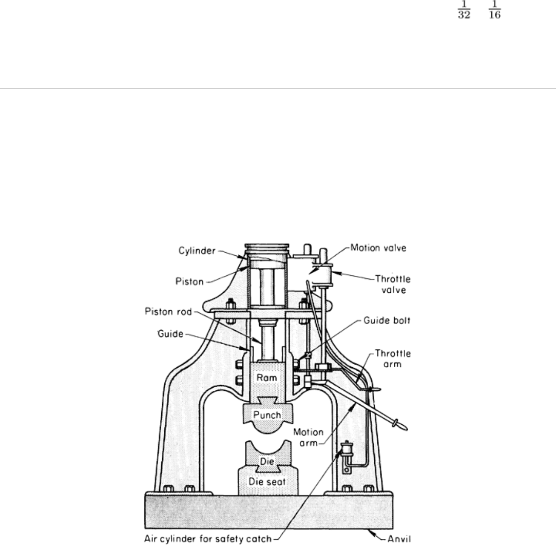
hammers, particularly the air-actuated types, have virtually replaced gravity-drop hammers. A typical air-drop hammer,
equipped for drop hammer forming, is shown in Fig. 1.
Fig. 1 Schematic of an air-actuated power-drop hammer equipped for drop hammer forming.
Power-drop hammers are rated from 4.5 to 155 kN (10M to 35,000 lbf), representing energies from 15 to 575 U (11,000
to 425,000 ft · lb). Air-drop hammers range in size (ram area) from 762 by 610 mm (30 by 24 in.) to 3.05 by 3.05 m (120
by 120 in.) with impact energies ranging from 8.9 to 134 kJ (6600 to 99,000 ft · lbf). Ram dimensions and other pertinent
details concerning these hammers can be found in the article "Hammers and Presses for Forging" in this Volume.
Planishing hammers are used to supplement drop hammer forming. These are fast-operating air-driven or motor-driven
machines that are generally used for low-production operations to form dual-curvature surfaces. They are also used to
planish welds and to smooth out wrinkles or other imperfections in drawn or drop hammer formed parts.
