ASM Metals HandBook Vol. 14 - Forming and Forging
Подождите немного. Документ загружается.

Effects of Spinning on Work Metal Properties
Power spinning is a severe cold-working operation and therefore has a marked effect on the mechanical properties of the
work metal. A well-defined and directional grain flow pattern is produced by power spinning. The surface finish of a spun
workpiece is usually good enough so that no additional machining is required after spinning. Spun finishes are commonly
about 1.5 m (60 in.), although finishes as smooth as 0.5 m (20 in.) have been produced by power spinning.
Strength and Hardness. In spinning, tensile and yield strengths increase, and ductility decreases. The magnitude of
effect depends on the amount of wall reduction and on the susceptibility of the metal to work hardening.
In many applications, the increase in strength caused by spinning is highly desirable because it eliminates the need for
heat treating. In other applications, the change in mechanical properties is not desired, and the workpieces must be
annealed after spinning.
To measure the work hardening in the deformation zone, Rockwell F (HRF) readings were taken on the cross section of a
spun copper workpiece that was reduced 43%. The results are shown in Fig. 12. It is evident that the area near the roller
contact has higher hardness than the area at the mandrel side.
Fig. 12 Hardness distribution (HRF) in a copper workpiece reduced 43% by spinning.
Spinning
Assembly by Spinning
Spinning is frequently used for less conventional applications than those described earlier in this article and in the article
"Tube Spinning" in this Volume. It is often the least expensive means of joining two or more parts to form an assembly.
For example, a tube can be inserted through a hole in a plate, and the protruding end of the tube can then be spun to
secure it to the plate. Small parts are assembled by this technique with a special tool rotated by a drill press.
Rubber-Pad Forming
Introduction
RUBBER-PAD FORMING, also known as flexible-die forming, employs a rubber pad or a flexible diaphragm as one
tool half, requiring only one solid tool half to form a part to final shape. The solid tool half is usually similar to the punch

in a conventional die, but it can be the die cavity. The rubber acts somewhat like hydraulic fluid in exerting nearly equal
pressure on all workpiece surfaces as it is pressed around the form block.
Rubber-pad forming is designed to be used on moderately shallow, recessed parts having simple flanges and relatively
simple configurations. Form block height is usually less than 100 mm (3.9 in.). The production rates are relatively high,
with cycle times averaging 1 min or less.
The advantages of the rubber-pad forming processes compared to conventional forming processes are:
• Only a single rigid tool half is required to form a part
•
One rubber pad or diaphragm takes the place of many different die shapes, returning to its original shape
when the pressure is released
• Tools can be made of low cost, easy-to-
machine materials due to the hydrostatic pressure exerted on the
tools
•
The forming radius decreases progressively during the forming stroke, unlike the fixed radius on
conventional dies
• Thinning of the work metal, as occurs in conventional deep drawing, is reduced considerably
• Different metals and thicknesses can be formed in the same tool
• Parts with excellent surface finish can be formed as no tool marks are created
• Set-up time is considerably shorter as no lining-up of tools is necessary
The disadvantages are:
•
The pad or diaphragm has a limited lifetime that depends on the severity of the forming in combination
with the pressure level
• Lack of sufficient forming pressure results in parts with less sharpness or with wrinkles, which ma
y
require subsequent hand work
• The production rate is relatively slow, making the process suitable primarily for prototype and low-
volume production work
Equipment. The hydraulic presses used in most flexible-die forming are similar to those described in the article "Presses
and Auxiliary Equipment for Forming of Sheet Metal" in this Volume. Some processes use special machines, which are
described in this article in the discussions of the specific processes. In most applications, only one solid tool half is
specially made. The tool half can be made of epoxy resin, zinc alloys, hardwood, or other inexpensive material, as well as
aluminum, cast iron, or steel.
Equipment is available with cycling rates as high as 1500 per hour. Some flexible-die forming methods have been applied
to high-volume production, such as the forming of deeply recessed taillight reflectors for automobiles, and the deep
drawing of toaster shells (Example 3).
The application of rubber pads in press-brake dies is discussed in the article "Press-Brake Forming" in this Volume. In the
past, flexible-die forming methods were designated by specific processes: Guerin process, Verson-Wheelon process,
trapped-rubber process, Marform process, Hydroform process, SAAB process, and Demarest process. Modern technology
has reduced this list, categorizing the methods into three basic groups: rubber pad, fluid cell, and fluid forming. Detailed
applications of these rubber-die forming processes to specific metals are available in the articles "Forming of Stainless
Steel," "Forming of Aluminum Alloys," "Forming of Copper and Copper Alloys," and "Forming of Titanium and
Titanium Alloys" in this Volume.
Rubber-Pad Forming
Rubber-Pad Forming
The Guerin process is synonymous with the term rubber-pad forming. An improvement over the Guerin process is the
Marform process, which features the addition of a blankholder and die cushion to make this process suitable for deeper

draws and to alleviate the wrinkling problems common to the Guerin process. Another variation of the Guerin process is
the trapped-rubber process, in which the forming force is provided by a hammer instead of a hydraulic press. Like the
Marform process, the trapped-rubber process can be used for deeper draws and results in less scrap due to wrinkling than
the basic Guerin process. The design and construction of the ASEA Quintus rubber-pad presses are further refinements of
the Guerin and Marform processes.
Guerin Process
The Guerin process is the oldest and most basic of the production rubber-pad forming processes. Its advantages are
simplicity of equipment, adaptation to small-lot production, and ease of changeover.
Some metals that are commonly formed by the Guerin process are listed in Table 1. Titanium can be formed only if the
workpiece and the form block are both heated. The resulting deterioration of the rubber pad often makes the process too
costly, as compared to forming by conventional dies.
Table 1 Metals commonly formed by the Guerin process
Maximum thickness
(a)
Metal
mm
in.
Mild forming
Aluminum alloys
2024-O, 7075-W
4.7
0.187
2024-T4
1.6
0.064
Austenitic stainless steels
Annealed
1.3
0.050
(b)
Quarter hard
0.8
0.032
(c)
Titanium alloys 1.0
0.040
(d)
Stretch flanging
Aluminum alloy 2024-T4
1.6
0.064
Austenitic stainless steels
Quarter hard
0.8 0.030
(a)
Typical; varies with type of equipment and part design.
(b)
Up to 2.0 mm (0.078 in.) when compression dams are used (see the section "Accessory Equipment" and Fig. 2 in
this article).
(c)
Only very mild forming.
(d)
When heated to 315 °C (600 °F)
Presses. For maximum forming capability, the force capacity of the press and the area of the rubber pad must be
suitable for the operation under consideration. The rubber pad is generally about the same size as the press ram, but it can
be smaller (Example 2).
Tools. The principal tools are the rubber pad and the form block, or punch (Fig. 1). The rubber pad is relatively soft
(about Durometer A 60 to 75) and is usually three times as deep as the part to be formed. The pad can consist of a solid
block of rubber, or of laminated slabs cemented together and held in a retainer, as shown in Fig. 1. The slabs can also be
held loose in a flanged retainer. The retainer is generally made of steel or cast iron, and it is approximately 25 mm (1 in.)
deeper than the rubber pad. It is also strong enough to withstand the forming pressures generated (up to 140 MPa, or 20
ksi, in some applications, although an upper limit of 14 MPa, or 2 ksi, is more common).
Fig. 1 Tooling and setup for rubber-pad forming by the Guerin process. Dimensions given in inches.
The minimum pad thickness is 1 times the height of the form block, as shown in Fig. 1. Pad thicknesses generally vary
from 152 to 305 mm (6 to 12 in.), and the most commonly used thickness is 203 to 229 mm (8 or 9 in.).
Form blocks are made of wood, plastic, masonite, cast iron, steel, or alloys of aluminum, magnesium, zinc, or bismuth.
The softer materials are used in making prototypes or experimental models or in small production runs. The life of a
wood, plastic, or soft-metal form block can be extended by facing it with steel. Form blocks are fitted with locating pins
to hold the blanks in position while they are being formed.
The form block is loosely mounted on a platen, or pressing block (Fig. 1), which fits closely into the rubber-pad retainer
to avoid extrusion of the rubber during the forming process. Several form blocks are often mounted on one platen so that
several parts can be formed simultaneously with one stroke of the press. Two or three platens can be used with each press;
they can be slid or rotated from under the press ram for loading and unloading.
Accessory equipment includes draw clips, cover plates, wiping plates, forming rings and forming bars, and dams and
wedge blocks. These are used to increase the pressure on the workpiece in specific locations and to aid in the forming of
difficult shapes.
Draw clips are fastened to the edge of a blank to equalize the drawing force on a flange and to keep it from wrinkling.
Wiping plates, usually hinged to the pressing block, mechanically transfer the pressure of the rubber pad to hard-to-form
flanges. Forming rings and forming bars work in the same way, except that they encircle the part and therefore are not
hinged. Dams are shaped and positioned so that with the sidewall of the form block they form a trap. The dam has a face
sloping toward this trap so that rubber is cammed against the sidewall as the rubber pad moves down, thus increasing the
pressure in that area. Wedge blocks use the same kind of camming action to apply mechanical pressure to the side of a
workpiece. Examples 1 and 4 in this article illustrate the use of dams. Cover plates are used to hold blanks flat during
forming or to protect previously formed areas from distortion.
Procedure. The rubber-pad retainer is fixed to the upper ram of the press, and the platen, containing the form block, is
placed on the bed of the press. A blank is placed on the form block and is held in position by two or more locating pins.
The pins must be rigidly mounted in the form block so that the rubber will not drive them down into the pinhole or push
them out of position; and they must be no higher than necessary to hold the blank, or they will puncture the rubber pad. In
some applications, nests can be used to locate the blank during forming.
As the ram descends, the rubber presses the blank around the form block, thus forming the workpiece. The rubber-pad
retainer fits closely around the platen, forming an enclosure that traps the rubber as pressure is applied. The pressure
produced in the Guerin process is ordinarily between 6.9 and 48 MPa (1 and 7 ksi). The pressure can be increased by
reducing the size of the platen. Pressures as high as 140 MPa (20 ksi) have been developed through the use of small
platens in high-capacity presses (see Example 1).
The pressure is not a function of the number of parts being formed, but of the platen area. To obtain maximum production
with each stroke of the press, therefore, as many form blocks as possible are mounted on a single platen. The depth of the
finished parts formed by this process seldom exceeds 38 mm (1 in.). However, deeper parts can be formed by using a
press with a high force capacity and a rubber pad with a small surface area. In one application, such a setup produced 140
MPa (20 ksi) of pressure and was able to form a flange 70 mm (2 in.) deep.
Straight flanges can be easily bent by the Guerin process if they are wide enough to develop adequate forming force. If
the flanges are not wide enough, accessory tools must be used.
Minimum widths for flanges of stainless steel and aluminum alloys that can be bent by rubber-pad forming are listed in
Table 2. Angles on flanges in soft metal can generally be held to a maximum variation of ±1°. In hard metals, such as
half-hard stainless steels, which have more springback than annealed stainless steels, a ±5° tolerance can be met only with
special care. An envelope (all-around) tolerance of ±0.38 mm (±0.015 in.) is possible on the contour of soft-metal pieces,
but on hard metal, the tolerance must be increased to ±0.51 mm (±0.020 in.).
Table 2 Minimum formable flange widths for the rubber-pad forming of stainless steels and aluminum alloys
Minimum flange width
(a)
Alloy and/or temper
mm
in.
Stainless steels
Annealed 4.8 + 4.5t
+ 4.5t
(b)
Quarter hard 16
Aluminum alloys
2024-O, 7075-O 1.6 + 2.5t
+ 2.5t
(b)
2024-T3, 2024-T4 3.2 + 4t
+ 4t
(b)
(a)
Using minimum permissible bend radius; a larger bend radius requires a wider flange.
(b)
t, sheet thickness
Stretch flanges and shrink flanges can be formed around curves and holes if the deformation is slight to moderate. If
forming is severe, auxiliary tools must be used to support the work and to prevent wrinkling.
Shallow Drawing. Cover plates are often used to hold webs flat while flanges are being formed. In the following
example, a pressure of 140 MPa (20 ksi) was used to form a part so well that only minimal hand reworking was required.
To obtain the 140 MPa (20 ksi) pressure, a rubber pad 508 mm (20 in.) in diameter (surface area: 0.19 m
2
, or 300 in.
2
)
was mounted in a 27 MN (3000 tonf) hydraulic press. The bed size of the press was 1520 mm (60 in.) front-to-back and
1570 (62 in.) left-to-right. Stroke length was 457 mm (18 in.), and shut height was 1270 mm (50 in.). The press had a
turntable that held two form blocks; therefore, one block could be unloaded and loaded while the other was under the
press ram. The rubber pad was 203 mm (8 in.) thick and made in two pieces. One piece was 178 mm (7 in.) thick and had
a hardness of Durometer A 80 to 85. The second piece, which was replaceable, was 25 mm (1 in.) thick and had a
hardness of Durometer A 70 to 75.
Example 1: Shallow Drawing of a Fuselage Tail Cap by the Guerin Process.
The fuselage tail cap shown in Fig. 2 was rubber-pad formed at 140 MPa (20 ksi) using the 27 MN (3000 tonf) hydraulic
press and the 508 mm (20 in.) diam pad described above. The cap was originally made by spinning, but at a rate of only
one piece per hour. Changing to high-pressure rubber-pad forming by the Guerin process increased the production rate to
12 pieces per hour.
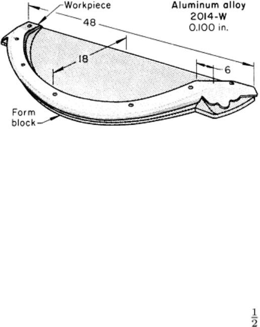
Fig. 2 Fuselage tail cap that was formed by the Guerin process in a high-pressure setup. D
imensions given in
inches.
A blank of aluminum alloy 2014-O, 0.81 mm (0.032 in.) thick, was solution heat treated to the W temper and was
lubricated with heavy-duty floor wax. The part was formed before age hardening was complete. A compression dam
surrounded the form block (Fig. 2) and was used to concentrate pressure on the flange.
Matched Laminations. In the following example, accurately matched laminations were made by forming one over the
other on a form block by the Guerin process.
Example 2: Forming of a Two-Piece Cockpit Rail on a Single Form Block.
By using a rubber pad instead of a conventional die, it was possible to form the two mating parts of a cockpit rail section
on a single form block. One of the two parts is shown in Fig. 3. The second part was formed over the first after it had been
formed.
Fig. 3 Cockpit rail section that was formed on a single form block by the Guerin process.
Dimensions given in
inches.
A fully developed blank, 2.54 mm (0.100 in.) thick, was cut from aluminum alloy 2014-O and solution heat treated.
Forming was done by the Guerin process with a minimum pressure of 52 MPa (7.5 ksi). No lubricant was used. The form
block (Fig. 3) was made of masonite and was plastic faced. The production rate was 20 pieces per hour.
Blanking. With the Guerin process, rubber pads can be used for blanking and piercing as well as for forming. Rubber
pads produce better edges on the workpiece than band sawing, and almost as good as those made by routing. An edge
radius up to the thickness of the metal can be produced on some heavy-gage metals. The rubber-pad method can blank
aluminum alloy 2024-O up to 0.81 mm (0.032 in.) thick and, for some shapes, up to 1.0 mm (0.040 in.) thick. The
minimum hole diameter or width of cutout is 50 mm (2 in.). A minimum of 38 mm (1 in.) trim is needed for external
cuts.
The form block has a sharp cutting edge where the blank is to be sheared. In hard-metal blocks, this edge can be cut into
the form block, as shown in Fig. 4(a) and 4(b). Form blocks of soft metal, plastic, or wood need a steel shear plate for the
cutting edge (Fig. 4c); the shearing edge should be undercut 3 to 6°.
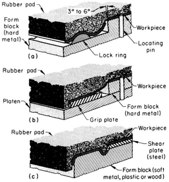
Fig. 4
Three techniques for blanking by the Guerin process categorized by clamping method. (a) Lock ring. (b)
Grip plate. (c) Raised extension of the form block.
The trim metal beyond the line of shear must be clamped firmly so that the work metal will break over the sharp edge
instead of forming around it. This clamping is done by a lock ring (Fig. 4a), a grip plate (Fig. 4b), or a raised extension of
the form block (Fig. 4c).
These clamping devices also localize pressure at or near the cutting line. A rounded edge on the finished blank can be
produced by locating the lock ring or grip plate a small distance from the shear edge (Fig. 4a and 4b). The metal droops in
the unsupported area and forms around the sharp corner before it shears. The result is a smooth, rounded edge.
Drawing of shallow parts is often done by a modification of the Guerin process in which the contour is recessed (for
example, a die cavity) into the form block rather than being raised on it. The blank is securely clamped between the
rubber pad and the surface around the recess before forming begins.
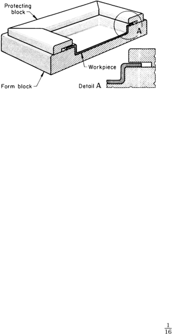
Clamping the work metal before drawing and the amount of pressure used are both important for successful drawing. The
work metal must be securely clamped to prevent it from flowing irregularly and subsequently forming wrinkles, but not
so tightly that the metal cannot flow at all, which will cause thinning, or even tearing, of the work metal. To avoid this,
either the edges can be lubricated or a protecting block with an undercut slot to accommodate the flange (Fig. 5) can be
placed over the edges of the workpiece. The width of the block and undercut must provide the correct balance between
clamping force and drawing force. The undercut should be 0.08 to 0.15 mm (0.003 to 0.006 in.) higher than the thickness
of the work metal.
Marform Process
The Marform process was developed to apply the
inexpensive tooling of the Guerin and Verson-Wheelon
processes (see the section "Verson-Wheelon Process" in
this article) to the deep drawing and forming of wrinkle-
free shrink flanges. A blankholder plate and a hydraulic
cylinder with a pressure-regulating valve are used with a
thick rubber pad and a form block similar to those used in
the Guerin process. The blank is gripped between the
blankholder and the rubber pad. The pressure-regulating
valve controls the pressure applied to the blank while it is
being drawn over the form block.
While forming a soft aluminum alloy blank, the diameter
can usually be reduced 57%, and reductions as high as
72% have been obtained. A shell depth equal to the shell
diameter is normal when the minimum stock thickness is
1% of the cup diameter. Depths up to three times shell diameter have been reached with multiple-operation forming. The
minimum cup diameter is 38 mm (1½ in.).
Foil as thin as 0.038 mm (0.0015 in.) can be formed by placing the blank between two aluminum blanks about 0.76 mm
(0.030 in.) thick and forming the three pieces as a unit. The inner and outer shells are discarded.
Presses. The Marform process is best suited to a single-action hydraulic press in which pressure and speed of operation
can be varied and controlled. A Marform unit comes as a package that can be installed in a hydraulic press having ample
stroke length and shut height. However, a press that incorporates a hydraulic cushion system into its bed has been
designed specifically for Marforming.
The rubber pressures used depend on the force capacity of the press and the surface area of the rubber pad. Recent
installations range from 34 to 69 MPa (5 to 10 ksi).
Tools. The rubber pad used in Marforming is similar to that used in the Guerin process. It is normally 1½ to 2 times as
thick as the total depth of the part, including trim allowance. The rubber pad can be protected from scoring by the use of a
throw sheet, which is either cemented to the pad or thrown over the blank.
Well-polished steel form blocks are used for long runs and deep draws. Aluminum alloy form blocks must be hard coated
to prevent galling for draws deeper than 38 mm (1½ in.). Masonite form blocks can be used if they can withstand the
abuse and wear of forming a particular part in a given quantity. When a cast shape is more economical, aluminum or zinc
alloy form blocks can be used.
Blankholder plates are usually made of low-carbon steel. The contact surface is ground flat and polished to avoid
scratching of the blank. Clearance between the form block and the mating hole in the blankholder is 0.76 to 1.52 mm
(0.030 to 0.060 in.) per side. The edge should have a 1.6 mm ( in.) radius.
A radius plate is necessary when the machine pressure is insufficient for forming the flange radius within tolerance. The
part is drawn first without the plate, then redrawn using the plate to form the exact radius. The radius plate is usually 13
mm (½ in.) thick and 25 mm (1 in.) wider than the workpiece. A sealing ring is used to prevent the rubber pad from
extruding out of the container.
Procedure. The blank rests on the blankholder plate above the form block. The rods supporting the seal ring and
blankholder plate (Fig. 6) are supported on a variable-pressure hydraulic cushion. As the press ram is lowered, the blank
is clamped between the rubber pad and the blankholder before forming begins. As the rubber pad continues to descend,
the blank is drawn over the form block while the pressure control valve in the hydraulic cushion releases fluid at a
controlled rate. The pressure in the hydraulic cushion must be adjusted to prevent wrinkles from forming in the flange but
to permit the blank to be drawn into a smooth shell. The part is stripped from the form block by the blankholder. The
following example describes an application of the process.
Fig. 5
Use of a protecting block to prevent work metal
irregularities in shallow drawing by the Guerin process.
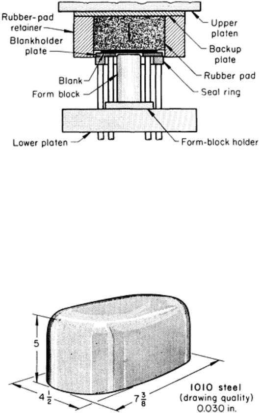
Fig. 6 Tooling and setup for rubber-pad forming by the Marform process.
Example 3: Deep Drawing of Toaster Shells by the Marform Process.
The toaster shell shown in Fig. 7 was deep drawn in large quantities (80,000 pieces) from 0.76 mm (0.030 in.) thick deep-
drawing-quality 1010 steel. The blanks were lubricated by brushing with a soap compound. Available pressure was 41
MPa (6 ksi). The depth of the trimmed shell was 127 mm (5 in.). The reduction time per piece was 22 s.
Fig. 7 Toaster shell that was deep drawn by the Marform process. Dimensions given in inches.
Drop Hammer Forming With Trapped Rubber
A process similar to the Guerin process, for forming shallow workpieces, is a trapped-rubber process, which uses a drop
hammer in place of the hydraulic press; the primary differences are the faster forming speed and the impact force of the
hammer. The use of rubber pads in drop hammer forming is illustrated in the article "Drop Hammer Forming" in this
Volume.
Figure 8 shows the effects of forming flanges on aluminum alloys 5052-O and 2024-O by the drop hammer (trapped-
rubber) and Guerin processes. When flanges deeper than 32 mm (1¼ in.) are made by the Guerin process, stretch flanges
can tear and shrink flanges can wrinkle. However, when the drop hammer process is used, fewer deformities occur (Fig.
8).