ASM Metals HandBook Vol. 14 - Forming and Forging
Подождите немного. Документ загружается.


Speeds that are best suited to manual spinning depend mainly on work metal composition and thickness. For example, a
given blank of stainless steel is successfully spun at 60 m/min (200 surface feet per minute, or sfm), and speed is
determined by "operator feel" to be maximum for the conditions. Under otherwise identical conditions, changing to an
aluminum blank will permit speeds of 120 to 180 m/min (400 to 600 sfm). Similarly, if the thickness of the stainless steel
blank were decreased to one-half the original thickness (no other changes), speed could be safely doubled or tripled.
Selection of optimal speed depends largely on "operator feel." In many spinning operations, speed is changed (usually
increased) during the operation by means of a variable-speed drive on the headstock.
Lubricants should be used in all room-temperature spinning operations, regardless of work metal composition,
workpiece shape, or type of spinning tools used. The usual practice is to apply the lubricant to the blank with a swab or
brush before loading the blank into the machine. In some cases, additional lubricant is added during operation as judged
necessary by the operator. The need for additional lubricant depends on the tenacity of the lubricant used and on blank-
rotation speed.
The most important property of a lubricant used for spinning is its ability to adhere to the rotating blank. Ordinary cup
grease is often used. It can be heated to reduce its viscosity, thus making it easier to apply to the blank. Upon application
to the cold blank, the viscosity of the grease increases. In addition, cup grease can be easily removed.
Other lubricants used for spinning include soaps, waxes and tallows (and proprietary mixtures of two or more of these
materials), and pigmented drawing compounds. All of these, however, are more difficult to remove than simple grease.
Therefore, the more tenacious lubricants are not used if an easier-to-remove lubricant will provide acceptable results.
Spinning
Power Spinning
Power spinning is also known as shear spinning, because in this method metal is intentionally thinned by shear forces as
high as 3.5 MN (400 tonf). Power spinning is used in two broad areas of application: cone spinning and tube spinning. In
cone spinning, the deformation of the metal from the flat blank is in accordance with the sine law (see the section
"Mechanics of Cone Spinning" in this article).
Virtually all ductile metals can be processed by power spinning. Products range from small hardware items made in large
quantities (metal tumblers, for example) to large components for aerospace applications in unit or low-volume production.
Blanks as large as 6 m (240 in.) in diameter have been successfully power spun. Plate stock up to 25 mm (1 in.) thick can
be power spun without applying heat. When heated, blanks as thick as 140 mm (5 in.) have been successfully spun.
Conical and curvilinear shapes are those most commonly produced from flat (or preformed) blanks by power spinning.
The mechanics of the process should be known and the rules followed when planning manufacturing processes that
include power spinning.
Mechanics of Cone Spinning
The application of shear spinning to conical shapes is shown schematically in Fig. 4. The metal deformation is such that
forming is in accordance with the sine law, which states that the wall thickness of the starting blank, t
1
, and that of the
finished workpiece, t
2
, are related as follows:
t
2
= t
1
(sin )
where is one-half the apex angle of the cone. When spinning in accordance with the sine law, the axial thickness is the
same as the thickness of the starting blank (Fig. 4).
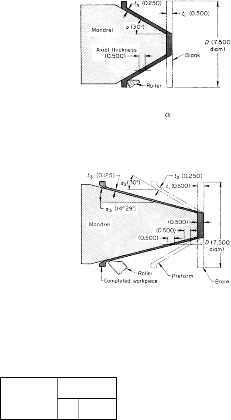
Fig. 4 Setup and dimensional relationships for the one-operation power spinning of a cone. D
, mandrel
diameter; t
1
, original (blank) thickness; t
2
, spun thickness; , included angle. Dimensions given in inches.
When spinning cones to small angles (<35° included angle), the best practice is to use more than one spinning pass with a
different cone angle for each pass, as illustrated in Fig. 5. When using this technique, the workpiece is annealed or stress
relieved between passes.
Fig. 5 Setup and dimensional relationships for the two-
operation spinning of a cone to a small angle (35°
included angle). Dimensions given in inches.
This practice permits a high total reduction while maintaining a practical limit of 50 to 75% between process anneals. The
reduction between successive annealing operations is determined by the maximum acceptable limits of deformation for
the metal being spun (Table 2); this value is obtained by multiplying t
1
by a factor (0.5 for 50%, 0.25 for 75%, and so on)
and then dividing the result by t
1
to obtain the sine of the required half angle.
Table 2 Recommended maximum reductions for the single-pass power spinning of various metals
Maximum reduction, %
Metal
Cone
Hemisphere

Aluminum alloys
2014
50
40
2024
50
. . .
3000
60
50
5086
65
50
5256
50
35
6061
75
50
7075
65
50
Pure beryllium
(a)
35
. . .
Copper 75
. . .
Molybdenum
(a)
60
45
Nickel-base alloys
Waspaloy
40
35
René 41
40
35
Steels
4130
75
50
4340
70
50
6434
70
50
D6ac
70
50
H11
50
35

Stainless steels
Type 321
75
50
Type 347
75
50
Type 410
60
50
17-7PH
65
45
A286
70
55
Titanium
(a)
Commercially pure
45
. . .
Ti-6Al-4V
55
. . .
Ti-3Al-13V-11Cr
30
. . .
Ti-6Al-6V-2.5Sn
50
. . .
Tungsten
(a)
45 . . .
(a)
Hot spun
Even in multiple-pass spinning, the original blank diameter is retained, and the exact volume of material is used in the
final part. At any diameter of either the preform or the completed workpiece, the axial thickness equals the thickness of
the original blank. For example, if a flat plate has a diameter of 190 mm (7 in.) and a thickness of 12.5 mm ( in.), the
spun preform has this same 12.5 mm ( in.) axial thickness, but the wall thickness is only 6.4 mm ( in.) (t
1
, Fig. 5),
thus satisfying the sine law. Similarly, the final workpiece has an axial thickness of 12.5 mm, ( in.), but in accordance
with the sine law, it has a wall thickness of only 3.2 mm ( in.) (t
3
, Fig. 5).
Effects of Deviation From the Sine Law. Deviation from the sine law is usually expressed in terms of
overreduction or underreduction. In overreduction, the final thickness of the workpiece is less than that dictated by the
sine law; in underreduction, the thickness is greater. In overreduction, the flange will lean forward; in underreduction, the
flange will lean backward. If a thin blank is spun with severe underreduction, the flange will wrinkle. This phenomenon
corresponds to a deep-drawing operation in which the blankholder pressure is insufficient.
In power spinning, overreduction has an additional effect on the shape of the workpiece. As the workpiece is overreduced,
back extrusion can occur (Fig. 6). For a given amount of reduction, the likelihood of back extrusion increases with
increasing mandrel angle (Fig. 6).
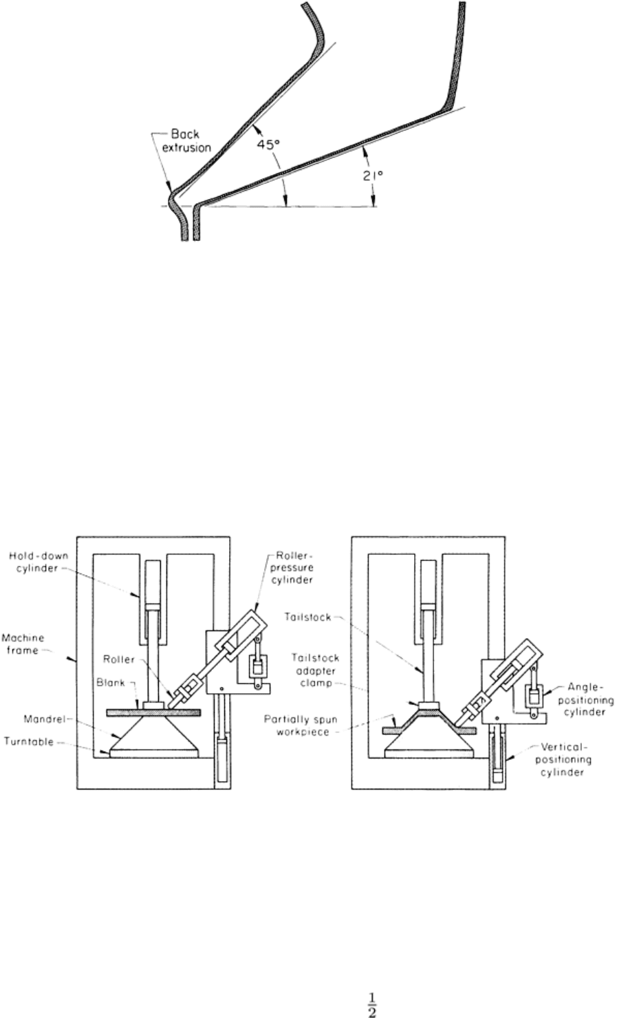
Fig. 6 Back extrusion as a result of overreduction in the power spinning of low-carbon steel.
The phenomenon of back extrusion in spinning is explained in terms of the compressive stress in the spun workpiece that
pushes the spun section backward. If the tailstock of the machine is removed, it is possible to obtain curvilinear shapes on
a conical mandrel by varying the amount of overreduction during spinning.
Machines for Power Spinning
Most power spinning is done in machines specially built for the purpose. The significant components of such a machine
are shown in Fig. 7. Although Fig. 7 illustrates the power spinning of a conical shape, similar machines are used for the
spinning of tubes (see the article "Tube Spinning" in this Volume).
Fig. 7 Schematic of power spinning in a vertical machine.
Machines for power spinning are usually described by specifying the diameter and length (in inches) of the largest
workpiece that can be spun and the amount of force that can be applied to the work. It is also common practice to specify
that the machine can spin a given thickness of metal at a 50% reduction in thickness in one pass.
The capacity of spinning machines ranges from 455 × 380 mm (18 × 15 in.) at 18 kN (4000 lbf) to machines capable of
spinning workpieces as large as 6 m (240 in.) in diameter × 6 m (240 in.) long. Force on the work can be as great as 3.5
MN (800,000 lbf). Machines have been built that spin steel 140 mm (5 in.) thick.
Spinning machines can be vertical or horizontal. Machines used for spinning workpieces 1.8 m (70 in.) or more in
diameter are usually vertical because they are better suited to handling large work.
Machines for power spinning can be automated to various degrees. Most spinning machines use template guides that
control the shape and accuracy of the workpiece. Most machines used for production spinning are semiautomatic; that is,
they are loaded and unloaded by the operator, but the entire spinning cycle is controlled automatically. Machines can also
be equipped with automatic loading and unloading devices, thus making them fully automatic.
Tools for Power Spinning of Cones
Mandrels, rollers, and other tools are subjected to more rigorous service in power spinning than in manual spinning;
therefore, more careful consideration must be given to design and materials of construction.
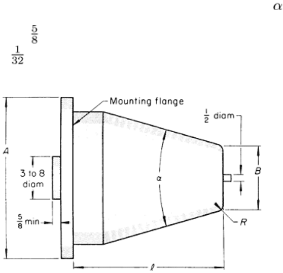
Mandrels. A typical mandrel profile is illustrated in Fig. 8. Dimensions A and B and angle can vary as required. Usual
practice is to have, first, an integral flange to permit the mandrel to be bolted to the headstock and, second, a boss of
suitable diameter and at least 16 mm ( in.) in thickness that fits into the headstock of the machine (Fig. 8). Radius R can
vary from a minimum of 0.8mm ( in.) to a round nose.
Fig. 8 Typical profile of a mandrel for the power spinning of cones. Dimensions given in inches.
Mandrel wear or failure is frequently a problem in the power spinning of conical shapes. The mandrels used in production
spinning must be hard in order to resist wear, and they must resist the fatigue resulting from normal eccentric loading.
Failure is often caused by spalling (flaking off). Mandrels can also be damaged by the rollers plunging into the workpiece
at the start of metal flow. The need for plunging can sometimes be eliminated by machining a ring on the preform to a
depth equal to the depth the rollers would otherwise be plunged. This technique permits the rollers to enter the machined
space before they start moving along the mandrel, thus eliminating the severe stress on the mandrel as spinning is begun.
Materials selection for the mandrels used in cone spinning depends primarily on the number of identical workpieces to be
spun. Based on quantity, the most commonly used materials are:
• Gray iron (as-cast) for the low-production spinning of soft metals (10 to 100 pieces)
•
Alloy cast iron (sometimes flame hardened in areas susceptible to high wear), for spinning 100 to 250
pieces
• 4150 or 52100 steel hardened to about 60 HRC, for spinning 250 to 750 pieces
• Tool steels such as O6, A2, D2, or D4 hardened to 60 HRC or slightly higher, for high production
The finish of the mandrels should be no rougher than 1.5 m (60 in.). The various diameters should be within ±0.025
mm (±0.001 in.) concentric with each other within approximately 0.05 mm (0.002 in.) total indicator reading.
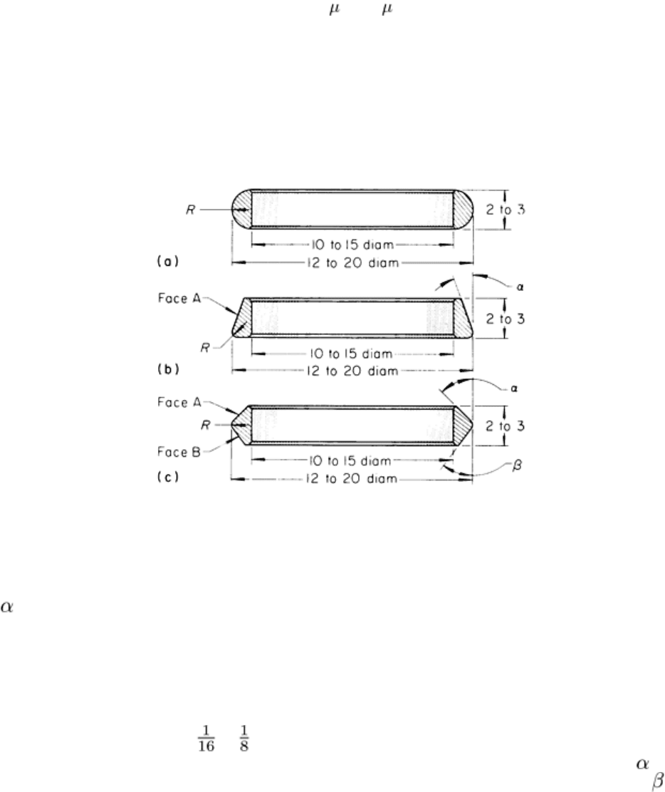
Rollers. Three types of rollers are shown in Fig. 9. Rollers are usually 305 to 510 mm (12 to 20 in.) in outside diameter,
depending on the type and size of the spinning machine. Roller widths are usually 50 to 75 mm (2 to 3 in.), and inside
diameters range from 255 to 380 mm (10 to 15 in.). The shape of the rollers depends largely on the shape of the
workpiece to be spun. Full-radius rollers (Fig. 9a) are usually used to produce curvilinear shapes, while those illustrated in
Fig. 9(b) and 9(c) are preferred for the spinning of cones.
Fig. 9 Typical rollers used in the spinning of cones and hemispheres. (a) Full-
radius roller. (b) Corner roller. (c)
Thinning roller. Dimensions given in inches.
Angle shown in Fig. 9(b) and 9(c) is necessarily varied to suit the work being spun (particularly the angle of the cone).
This angle is intended for clearance and should be such that the work metal does not touch face A (Fig. 9b) or either face
A or face B (Fig. 9c). The radius R should not be less than the final wall thickness.
The type of roller illustrated in Fig. 9(b) is widely used in cone spinning. A typical setup, using two of these rollers
opposed, is illustrated in Fig. 10. When two rollers are used to spin a part from flat plate, the rollers are set the same.
However, when spinning is done from a preformed shape, common practice is to make one the lead roller and to set it
ahead of the other by 1.6 to 3.2 mm ( to in.). If more than two rollers are used, this increment is continued between
successive rollers. The angle between the axis around which the rollers revolve and the workpiece (angle , Fig. 10) is
usually about 10°, while the angle between the same roller axis and the peripheral face of the roller (angle , Fig. 10)
may vary and is shown in Fig. 10 as approximately 30°.
Rollers are made from a variety of hard materials. The five
materials most widely used for the power spinning of
conical shapes, in order of ascending wearability and cost,
are W2 tool steel, O6 tool steel, D2 tool steel, D4 tool
steel, and carbide. Choosing among these materials is
usually done on the basis of quantity of workpieces to be
spun. The less costly W2 and O6 tool steels are generally
suitable for low-to-medium production quantities. Tool
steels D2 and D4 are preferred to high production
quantities. Carbide is seldom used except for specialized
applications in which the need has been proved and the
high cost can be justified.
Rollers made from any of the above tool steels should be
hardened to 60 to 65 HRC. All rollers should be polished
to a maximum surface roughness of 0.25 m (10 in.).
Auxiliary tools for cone spinning include tailstock
adapters, tracer templates, tracer followers, and stripping
devices. A tailstock adapter clamps the work to the
mandrel (Fig. 7) and is made of carbon or alloy steels or of
tool steel. The clamping face of the tailstock adapter must
be ground square to the spindle axis.
Tracers are used to spin workpieces that vary in wall
thickness or shape. Tracer templates are made of low-
carbon steel, such as 1020, that is, 3.2 to 4.8 mm ( to in.) thick. Large templates have lightening holes for easier
handling. Tracer templates are made to the same standards of accuracy as dies and similar tools. Tracer followers can be
ball bearings or hardened tool steel fingers, depending on cone shape.
Stripping devices can be full rings or fork-type fingers, attached to the roller carrier. The need for stripping devices
depends on the size and shape of the workpiece.
The use of preforms is common in cone spinning when the included angle of the cone is less than 35° or when the
percentage of wall reduction is high. Preforms are usually prepared by cold forming in a die, although hot forging or
machining or a combination of both can be used. Some preforms are made by spinning.
Speeds and Feeds for Cone Spinning
Most metals spin best at high speeds. The minimum speed considered to be practical is about 120 m/min (400 sfm), but
speeds this low are seldom used except for the spinning of small-diameter workpieces. Machine spindles sometimes
cannot rotate fast enough with such workpieces to achieve the desired surface speed. Speeds of 305 to 610 m/min (1000
to 2000 sfm) are most widely used, regardless of work metal composition, workpiece shape, or reduction per pass.
Feed. Most cone-spinning operations are done at feeds of 0.25 to 2 mm/rev (0.01 to 0.08 inches per revolution, or ipr). In
practice, however, feeds are usually calculated in millimeters per minute (mm/min) or inches per minute (ipm). Most
machines used in cone spinning are equipped with electronic or hydraulic devices that steplessly change the rate of feed
as the diameter on which the rollers are working changes continuously. The rate of feed usually ranges from 38 to 380
mm/min (1 to 15 ipm).
Feed rate is important, because it controls the workpiece finish and the fit of the workpiece to the mandrel. With all other
factors constant, an increase in feed rate will make the workpiece fit tighter on the mandrel, and the finish of the
workpiece will coarsen. On the other hand, a decrease in feed rate will cause a loose fit, and workpiece finish will
improve. The diameter of the mandrel should be the same as the inside diameter required on the workpiece (no allowance
for springback), and the workpiece should be spun to fit the mandrel. The fit may be loose, snug, or tight.
Fig. 10
Relative positions of rollers and workpiece in
the spinning of a cone.
To find the optimal combination of speed, feed, and pressure, a few pieces should be spun experimentally when a new job
is set up. During continuous operation, the temperature of the mandrels and spinning tools changes; therefore, after the
first hour or so, it is often necessary to adjust the pressure, speed, and feed for uniform results.
Power Spinning of Hemispheres
The use of preforms to control percentage of reduction has enabled power spinning to be applied to the forming of
hemispheres, ellipses, ogives, and in general, any curvilinear surface of revolution. However, the design of the preform
for curvilinear shapes is more complicated than that for conical shapes. In the spinning of conical shapes, it is possible to
find an axial thickness of the spun part that corresponds to the thickness of the blank (Fig. 5). No such relationship exists
for a curvilinear surface. In the path from the pole to the equator, the axial thickness of the metal on a hemisphere changes
from stock thickness at the pole to infinity at the equator (the inverse of sin 0° being infinity). The blank thickness must
be back tapered to compensate for the change in thickness that will take place during spinning. This is shown in Fig. 11;
the machined taper started at 3.8 mm (0.150 in.) in thickness (in the center of the blank) and ended at 7.6 mm (0.300 in.)
in thickness at the circle where the 30° radial line of the sphere was projected to the blank. At the corresponding 45° line,
the blank thickness was 5.38 mm (0.212 in.); at the 15° line, 14.73 mm (0.580 in.). Below the 30° line, however, the
reduction was greater than permissible for the material, and the operation was planned as if spinning a cylinder. The blank
for this portion had a flange with a thickness proportional to the percentage of reduction.
A usable blank can be designed by first finding in Table
2 the allowable reduction for the work metal to be used.
A beginning stock thickness should be selected that,
with the maximum reduction, will give the thickness
desired on the sphere. The ratio of finished stock
thickness to original stock thickness is then taken as the
sine of an angle, which will be the angle of the surface at
the latitude at which preforming must start. Beyond this
point, the reduction required to make the hemisphere
will be greater than is permissible for the work metal.
There will be no reduction at the pole, because at that
point blank thickness and final thickness will be the
same. At 45° from the pole, final part thickness will be
0.707 times the original thickness (sin 45° = 0.707). At a
corresponding circle on the blank, therefore, the original
thickness must be 1.414 times the final part thickness.
Other latitudes can be similarly chosen, and necessary
stock thickness at a corresponding circle on the blank
determined. Preforming must start at the circle
corresponding to the limiting latitude (the point where
the maximum permissible reduction has taken place). In
a cross-section view, the circles resulting from the above
method will appear as points, and the thickness of the
stock at these points can be determined. When the points
are laid out, a dozen or more points are connected to
yield the final part shape.
In modern shops, such calculations are usually performed with the aid of a computer. It is common practice in such
systems to use 1200 to 1500 points on a shape such as a large hemisphere.
The thickness of the starting blank can be obtained by multiplying the known thickness of the finished part by an
appropriate factor. Similarly, by dividing the starting blank thickness by the appropriate factor, the thickness of the
finished part is obtained. The factors are related to the percentage of reduction and are the reciprocal of the difference
between the percentage reduction (expressed as a decimal) and one, as follows:
• For 50% reduction, use a factor of 2
• For 66 % reduction, use a factor of 3
• For 75% reduction, use a factor of 4
Fig. 11
Hemisphere spun from a machined and
preformed blank. Dimensions given in inches.

• For 80% reduction, use a factor of 5
Use of this system is illustrated in the following example.
Example 1: Forming a 1.5 m (60 in.) Diam Hemisphere by Power Spinning.
Large hemispheres (Fig. 11) were power spun from solution-treated aluminum alloy 6061 using the following
calculations. From Table 2, it was determined that a 50% reduction could be made with this alloy. Preliminary
calculations for thickness of the starting blank were as follows:
t = final wall thickness · factor for percentage reduction
= 3.81 mm (0.15 in.) · 2
= 7.62 mm (0.300 in.)
In calculating the blank thickness at various points on the sphere, it was found that at the pole, or 90° point, the thickness
had to be reduced to 3.81 mm (0.150 in.) and that some reduction was required out to a point directly above the 30°
tangency on the hemisphere, where the thickness of the starting blank had to be 7.62 mm (0.300 in.). Beyond this point, a
flange would be preformed by spinning, and an additional thickness would be required. It was estimated that an increase
in blank thickness of 30% would be enough, and initial blank thickness established at 9.91 mm (0.390 in.).
Machining of the blank to graded thickness was done in a tracer-controlled vertical boring mill, with the blank held on a
vacuum chuck. After machining, the flange was preformed to the desired contour by conventional power spinning,
accomplishing a reduction in wall thickness that provided a uniform 7.62 mm (0.300 in.) wall.
Final spinning was accomplished in one pass of the rollers after the alloy was given a controlled amount of room-
temperature aging (usually 13 to 18 h). During final spinning one roller led the other by a vertical offset of 1.6 to 3.2 mm
( to in.), using 19 mm ( in.) radius tool rings at a feed of about 2.3 mm/rev (0.09 ipr). Speed varied from 300 rpm
maximum down to 40 rpm at the flange.
The procedure described in Example 1 has also been successfully applied to the forming of hemispheres and ellipses 152
mm to 1.8 in (6 to 70 in.) in diameter from 17-7 PH and type 410 stainless steels, from alloy steels such as 4130 and 4140,
and from aluminum alloys 5086, 2014, and 2024 (as well as 6061). In one case, the procedure was used for the hot
spinning of an ogive 762 mm (30 in.) in diameter and length from molybdenum.
Hot Spinning of Hemispheres. The use of heat for decreasing the strength and increasing the ductility of the work
metal is sometimes required because the machine capacity is insufficient for cold forming the thickness to be spun or
because the room-temperature ductility of the work metal is too low. Hot spinning is done only when necessary, because
heating, subsequent cleaning, and increased tool deterioration all contribute to increased cost.
Lubricants and Coolants for Power Spinning
Power spinning requires the use of a fluid that serves as both a lubricant and a coolant. Because of the large amount of
heat generated, a water-base fluid is most commonly used. Usually, a colloidal suspension of zinc in lithium soap or
molybdenum disulfide paste is mixed with water to function as the lubricant. These lubricant-coolant combinations are
satisfactory for most metals, although zinc-free lubricants and coolants should be used for the spinning of stainless steel to
avoid surface contamination.
Various oils and oil mixtures, such as 10% lard oil in kerosene, have also been successfully used for power spinning.
Regardless of composition, the fluid must be free flowing and applied by pumps in copious amounts, or both workpieces
and tools will be damaged from heat.
When spinning aluminum or stainless steel, the workpieces or mandrels or both are sometimes coated with the lubricant
before spinning. During spinning, workpieces and tools are flooded with a coolant, such as an emulsion of soluble oil in
water.