ASM Metals HandBook Vol. 14 - Forming and Forging
Подождите немного. Документ загружается.

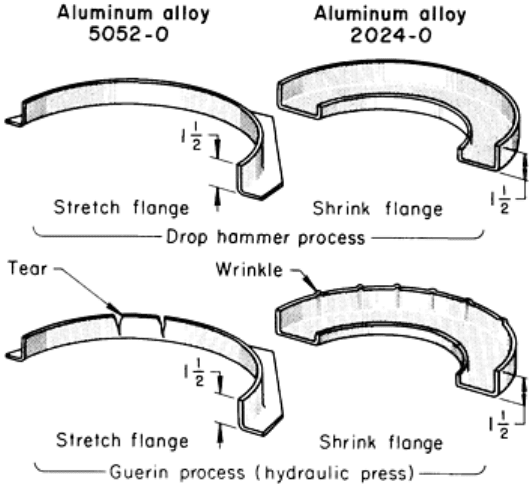
Fig. 8 Effect of impact in forming stretch and shrink flanges by the drop hammer (or trapped-
rubber) and
Guerin processes. Dimensions given in inches.
ASEA Quintus Rubber-Pad Press
ASEA presses, generally designed with force capacities of 50 to 500 MN (5600 to 56,000 tonf), are constructed of wire-
wound frames and have separate guiding columns (Fig. 9). By winding the press frames with prestressed wire, only
compressional stresses are present in the large castings or forgings of the yokes and columns, even when subjected to
maximum forming pressure. Therefore, when the press is loaded, the frame remains in slight compression, and the major
structural components never operate in the tensile mode.
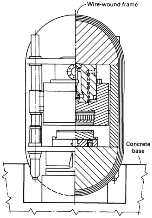
Fig. 9 Schematic of ASEA Quintus rubber-pad hydraulic press with wire-wound frame.
The press is equipped with a forged-steel rubber-pad retainer that has a replaceable insert to allow for forming at even
higher pressures. Although the maximum tool height is sacrificed by using these high-pressure inserts, cutting the work
area in half doubles the maximum forming pressure of the press when needed.
Standard table sizes range from 0.7 × 1.0 m (28 × 39 in.) to 2 × 3 in (79 × 118 in.). These presses provide forming
pressures to 100 MPa (15 ksi). Hard and brittle materials such as titanium, along with the die, can be heated outside the
press by an infrared heater; blanks can also be heated by conduction from the table through the heat transferred through
the die (Fig. 10).
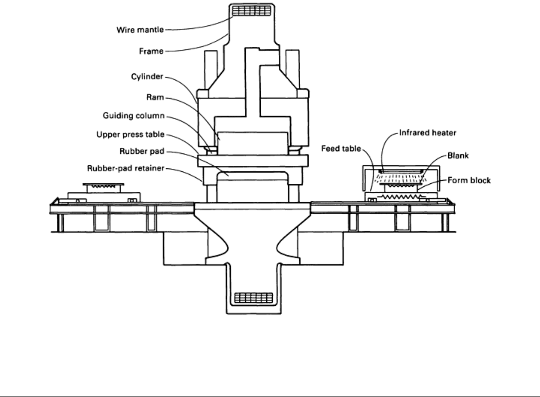
Fig. 10 Schematic of ASEA Quintus rubber-
pad press with provision for heating hard and brittle materials using
infrared heater or heating elements contained in feed table.
Rubber-Pad Forming
Fluid-Cell Forming
Initially developed as the Verson-Wheelon process, the fluid-cell process uses a fluid cell (a flexible bladder) backed up
by hydraulic fluid to exert a uniform pressure directly on the form block positioned on the press table. This process can be
classified in terms of the presses used (Verson-Wheelon and ASEA Quintus) as well as a specialized method (Demarest
process) for producing cylindrical and conical parts. The Verson-Wheelon press has cylindrical press housings of
laminated, prestressed steel that serve as pressure chambers. The ASEA Quintus press has a forged steel cylinder that is
wound with high strength steel wire to create a prestressed press frame with extremely good fatigue properties.
Fluid-cell forming can be used for recessed parts that are beyond the capabilities of rubber-pad forming, for all flange
configurations (including C-shaped flanges), and for complex parts with reentrant features and intricate joggles.
Maximum form block height is 425 mm (16.7 in.), and typical cycle time is 1 to 2 min.
Verson-Wheelon Process
The Verson-Wheelon process was developed from the Guerin process. It uses higher pressure and is primarily designed
for forming shallow parts, using a rubber pad as either the die or punch. A flexible hydraulic fluid cell forces an auxiliary
rubber pad to follow the contour of the form block and to exert a nearly uniform pressure at all points.
The distribution of pressure on the sides of the form block permits the forming of wider flanges than with the Guerin
process. In addition, shrink flanges, joggles, and beads and ribs in flanges and web surfaces can be formed in one
operation to rather sharp detail in aluminum, low-carbon steel, stainless steel, heat-resistant alloys, and titanium.
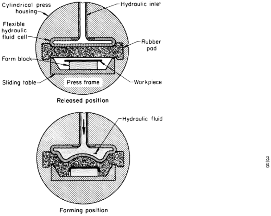
Presses. The Verson-Wheelon press has a horizontal cylindrical steel housing, the roof of which contains a hydraulic
fluid cell (Fig. 11). Fluid-cell bladders can be of neoprene or polyurethane composition. Hydraulic fluid is pumped into
the cell, causing it to inflate or expand. The expansion creates the force needed to flow the rubber of the work pad
downward, over and around the form block and the metal to be formed.
Below the chamber containing the rubber pad and
the hydraulic fluid cell is a passage, extending the
length of the press, that is wide and high enough to
accommodate a sliding table containing form
blocks. At each end of the passage is a sliding table
that is moved into position for forming.
The rubber pad used in the Verson-Wheelon process
has a hardness of about Durometer A 35. It is
usually protected from sharp corners on the form
block and blank by a throw sheet or work pad that is
harder and tougher than the pad itself. The throw
sheet is much less costly to replace than the rubber
pad below the fluid cell.
Verson-Wheelon presses are available with forming
pressures ranging from 35 to 140 MPa (5 to 20 ksi)
and force capacities of 22 to 730 MN (2500 to
82,000 tonf). Sliding tables range in size from 508 ×
1270 mm (20 × 50 in.) to 1270 × 4170 mm (50 ×
164 in.). The larger machine can form parts having
flange widths to 238 mm (9 in.).
Heating elements can be used with the sliding tables
for producing parts made of magnesium. The
maximum temperature is 315 °C (600 °F), and
special heat-resistant throw pads are used to protect
the hydraulic fluid cell.
Tools. The form blocks for the Verson-Wheelon
process are made in much the same way as those for
the Guerin process. Compression dams or deflector
bars can be used to direct pressure into local areas for forming shrink flanges or return bends, as described in Example 4.
Aluminum alloy or zinc alloy form blocks are recommended. Because of the high pressures, masonite or wood form
blocks may break down from repeated use. More than one form block can be used at a time; the quantity depends on the
size and shape of the form block.
Damage to the rubber pad can be reduced by removing all burrs and sharp edges from the blank. Form blocks should be
smooth; all sharp corners and projecting edges should be well rounded; high tooling pins should be eliminated; deep
narrow crevices or gaps between parts of form blocks should be eliminated; holes in blocks should be plugged during
forming.
Procedure. The sliding table containing the form blocks is loaded and slid into the press. Hydraulic fluid is pumped into
the cell, expanding it and driving the rubber pad down against the workpiece and around the form blocks. The pressure is
released, and the table of formed pieces is slid out, unloaded, and reloaded for another cycle.
Repositioning the form blocks after a few cycles will distribute the wear on the rubber pad and lengthen its life. The use
of a hard-rubber (or occasionally leather) pad slightly larger than the blank assists in the uniform forming of flanges and
prevents wrinkles.
Fig. 11 Principal components of the Verson-Wheelon process.
The cycle time for the Verson-Wheelon process is longer than that of conventional presses, such as those used with the
Guerin process. To reduce cell filling and draining time, it is good practice to load the table to capacity or to have dummy
blocks on the sliding table when only one part is being formed.
In the following example, the time to form a part in a Verson-Wheelon press was less than when the part was made by the
Guerin process. The higher forming pressure completely formed the part in one operation (whereas the Guerin process
had required two operations) and reduced hand work after machine forming.
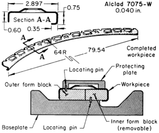
Example 4: Verson-Wheelon Versus Guerin Process for the Forming of a Complex Part.
The complex part shown in Fig. 12 was originally formed by the Guerin process in a 40 MN (4500 tonf) hydraulic press
from 1.0 mm (0.040 in.) thick alclad aluminum alloy 7075-W. The improved method used a Verson-Wheelon press that
could exert a pressure of 69 MPa (10 ksi) and had a capacity of 360 MN (41,000 tonf). A pressure of 48 MPa (7 ksi) was
needed to form the part. The same tool was used for both processes.
In the Guerin process, forming was done in two
operations. Joggles and stringer tabs were set by hand
after forming. In the first press operation, the outer
flange was formed, and the inner and return flanges
were partly formed. In the second press operation, the
forming was completed with rubber strips confined by
the dams.
In the Verson-Wheelon process, the outer, inner, and
return flanges and the joggles were formed in one
operation. This translated into a 30% labor-cost
advantage for the Verson-Wheelon process over the
Guerin process for this workpiece.
The heat-treated aluminum alloy 6061 form block was
mounted to a baseplate, with the inner and outer rims
acting as dams. Because of the return flange on the
inside radius of the part, the aluminum alloy form
block was split longitudinally, and the outer half was
fastened to the baseplate (see tooling setup in Fig. 12).
The inner half, bushed and located on pins projecting
from the baseplate, was removed from the base with
the finished part. Locating holes in the blank and the
outer form block matched locating pins in the cover
plate.
The 127 × 2240 mm (5 × 88 in.) blank was routed, and lightening holes were individually pierced and flanged, in a punch
press in both processes before rubber-pad forming. After forming, the part was aged to the T6 temper. The production lot
was 20 pieces. Several thousand pieces were produced on the form blocks.
Secondary Operations. Even though higher forming pressures are used, many pieces made by the Verson-Wheelon
process (as well as by the Guerin process) need hand work to remove wrinkles and to add definition to details. A further
refinement in the use of throw pads is a shaped rubber pad. Pad laminations are built up around a cavity that approximates
the shape of the part, so that flow of the rubber is less severe and forming pressure is more evenly distributed than with
the conventional flat rubber pad. The shape of the cavity is only approximate and can be used for similar parts.
Demarest Process
Cylindrical and conical parts can also be formed by a modified rubber bulging punch. The punch, equipped with a
hydraulic cell, is placed inside the workpiece, which is in turn placed inside the die. Hydraulic pressure expands the
punch. Forming with an expanding punch using the Demarest process is described in the following example.
Example 5: Use of Expanding Punches to Form Aircraft Fuel-Tank Sections.
Fig. 12 Complex part that was formed in a Verson-
Wheelon press. Dimensions given in inches.
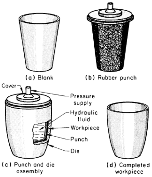
Aluminum alloy workpieces, rolled and welded into cones (Fig. 13a), were formed into aircraft fuel-tank sections with
expanding rubber punches (Fig. 13b). The cones were lowered into cast iron dies, which weighed 1600 kg (3500 lb) each
and were designed to withstand 10 MPa (1.5 ksi) of forming pressure.
The rubber punch was lowered into the workpiece, and a steel
cover was clamped over the whole assembly (Fig. 13c). The
punch was expanded under 2800 kPa (400 psi) of hydraulic
pressure, which formed the work metal into the curved shape
of the die (Fig. 13d).
The time taken for the entire process, including dismantling of
the die and unloading of the workpiece, was 3 min. In contrast,
spinning requires 15 to 20 min.
ASEA Quintus Fluid Cell Process
The ASEA Quintus fluid cell process is a further development
of the Guerin process, allowing deeper and more complex
parts to be formed. It uses a flexible rubber diaphragm backed
up by oil as either the male or female tool half. The
pressurized diaphragm forces the blanks to assume the shape
of the solid-tool halves. The high uniform hydrostatic pressure
permits the forming of shallow- to medium-depth parts with
complex shapes to final shape, practically eliminating the
subsequent hand forming usually required to apply the Guerin
process.
Presses. The ASEA Quintus fluid cell press (Fig. 14)
consists of a horizontally placed cylindrical press frame, two
rectangular, independently operated press tables on each side
of the press, and all electric and hydraulic equipment necessary
to operate the press placed on top of and alongside the press.
The press frame is a forged steel cylinder that has been wound
under pre-stress with high strength steel wire, so that only compressional stresses can occur in the steel forgings, even at
maximum pressure. Therefore, the fatigue properties of the Quintus wire-wound frame are excellent and the risk of
fracture virtually eliminated.
Fig. 13 Forming of a fuel-
tank section from a blank
using the Demarest process.
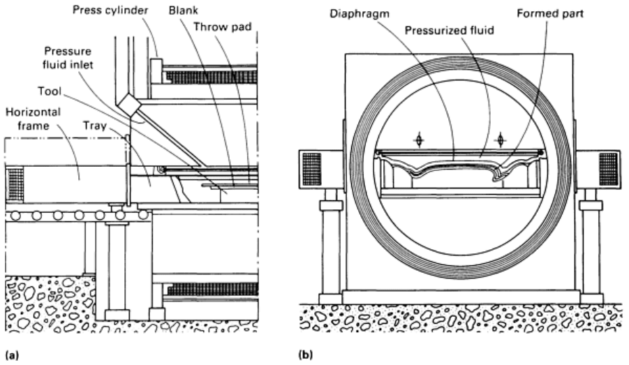
Fig. 14
Illustration of the principal components of a new generation ASEA Quintus fluid cell press. (a) Tray
containing blanks inserted into press prior to pressurizing. (b) Pressurized fluid cell diaphragm forming a blank.
A diaphragm (bladder) of natural rubber is located inside the press and covers the entire surface of the press table.
Hydraulic fluid is pumped into the cell created by the frame and the diaphragm, and the diaphragm is forced by the
increased pressure to expand into the table, which forces the blank to assume the shape of the form block, thus forming
the part. Once forming is done, the table is shuttled out to one side of the cylindrical press frame, and the table on the
other side can be shuttled inside the press to allow forming of parts placed on that table.
In the new generation of ASEA Quintus fluid cell presses, the flexible diaphragm can be changed in less than 30 min. No
rubber pad is required, and the diaphragm, which is made of natural rubber, can be repaired on-site should a sharp corner
of a tool or blank penetrate the roll-up pad that rolls out to cover the press table when it is shuttled into the press.
ASEA Quintus fluid cell presses are available with maximum forming pressures ranging from 100 to 200 MPa (14 to 29
ksi) and force capacities up to 1400 MN (157,000 tonf). The forming tables range in size from 700 × 2000 mm (27.5 ×
78.7 in.) to 2000 × 5000 mm (78.7 × 196.8 in.). The large presses can accommodate tools as high as 425 mm (16.7 in.)
and consequently form parts as deep or flanges as wide as 425 mm (16.7 in.).
Tools. Because of the uniform hydrostatic pressure exerted by the press on the tools, they can be made of low-strength
and low-cost tool materials such as hardwood, bakelite, epoxy, zinc-alloy, and so on, as well as of stronger materials such
as aluminum, cast iron, and steel. Depending on the shape of the part, and tolerance and surface finish requirements, parts
can be formed over a male die (form block), in a female die, or in an expansion die. The side of a part requiring a high
surface finish should face the diaphragm, while the side of a part requiring close tolerances should face the tool. Parts
with complex shapes and tight radii or made of high strength materials, demanding high pressures, and parts required in
large quantities may require tools of zinc or aluminum alloys.
Procedure. The ASEA Quintus fluid cell press has two independently operated press tables. This allows parts to be
unloaded and new blanks loaded on tools on one press table while parts are being formed on the other table inside the
press. A press table can be loaded with one large single tool half occupying the full size of the table or several smaller
tool halves; the number is restricted only by the size of the table.
Once blanks are loaded on the tools, the table is shuttled into the cylindrical press frame to a position where the flexible
diaphragm, located in the upper half of the press, covers the entire table area. Oil is then pumped into the cell, causing the
diaphragm to expand, which forces the blanks to assume the shapes of the tools. When the parts are formed, the pressure
is relieved and the oil is evacuated from the cell allowing the table to be shuttled out from the press so that parts can be
unloaded from the tools. The cycle time for a Quintus fluid cell is usually 1 to 3 min, depending on the press size and
forming pressure selected.
Rubber-Pad Forming
Fluid Forming
In contrast to conventional two-die forming, which produces local stress concentrations in a workpiece, fluid forming
(previously classified as rubber-diaphragm forming) employs a flexible-die technique that inhibits thinning and crack
initiation due to the uniformly distributed pressure. In the fluid forming process, a rubber diaphragm serves as both the
blankholder and a flexible-die member. Fluid forming differs from the rubber-pad and fluid-cell processes in that the
forming pressure can be controlled as a function of the draw depth of the part.
Fluid forming was initially known as the Hydroform process. The process, as originally conceived, is incorporated into
the Verson Hydroform press. After a hydraulic pump delivers fluid under pressure into the pressure-dome cavity, the
punch containing the die is driven upward into the cavity against the resistance provided by the fluid, and the workpiece is
formed.
In the SAAB rubber-diaphragm method, hydraulic fluid being compressed by the press piston alone (no moving die is
involved) forces the workpiece to assume the contour of the die. Air vents incorporated into the die facilitate the removal
of trapped air and eliminate blisters on the surface of the workpiece. The ASEA Quintus fluid forming press was
developed through slight modification of the SAAB process and optimization of press specifications with easily
changeable pressure domes.
Another adaption of the fluid forming method is the ASEA Quintus technique used in the ASEA Quintus deep-drawing
fluid forming press. Dome pressure and punch draw are both controlled from below the blank by two concentric rams,
each of which governs one of these two variables. The units have interchangeable pressure domes.
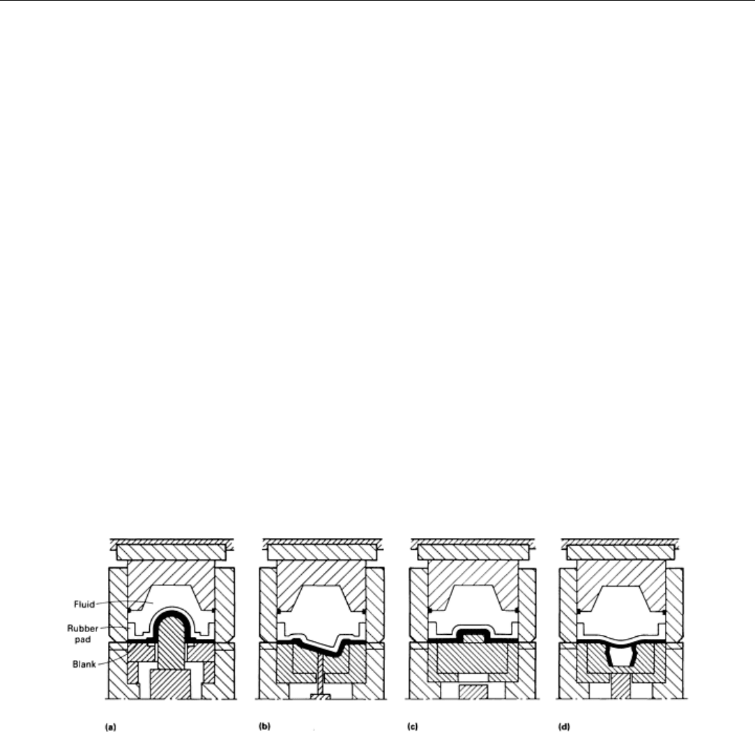
Fluid forming is intended for punch, cavity, hydroblock, or expansion forming of deep-recessed parts (Fig. 15). Cycle
time is 15 to 20 s for most parts.
Fig. 15
Four forming techniques that can be used in a fluid forming press. (a) Punch draw. (b) Cavity draw. (c)
Hydroblock draw (male-die forming). (d) Expansion draw.
Verson Hydroform Process
This process differs from those previously described in that the die cavity is not completely filled with rubber, but with
hydraulic fluid retained by a 64 mm (2½ in.) thick cup-shaped rubber diaphragm. This cavity is termed the pressure dome
(Fig. 16). A replaceable wear sheet is cemented to the lower surface of the diaphragm, as shown in Fig. 16. More severe
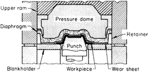
draws can be made by this method than in conventional draw dies because the oil pressure against the diaphragm causes
the metal to be held tightly against the sides as well as against the top of the punch.
Reductions in blank diameter of 60 to 70% are common for
a first draw. When redrawing is necessary, reductions can
reach 40%. Low-carbon steel, stainless steel, and aluminum
in thicknesses from 0.25 to 1.65 mm (0.010 to 0.065 in.) are
commonly formed. Parts made of heat-resistant alloys and
copper alloys are also formed by this process.
Presses. A special press, called a Hydroform press, is used
for this process. A lower hydraulic ram drives the punch
upward; the upper ram is basically a positioning device. A
hydraulic pump delivers fluid under pressure to the pressure
dome. The blankholder is supported by a solid bolster and
does not move during the operation.
Dome pressures range from 41 to 103 MPa (6 to 15 ksi), and
punch force capacities vary from 3.2 to 19 MN (368 to 2089
tonf). Special guide pins and a platen adaptor convert a standard Hydroform press into a single-action conventional
hydraulic press with a force capacity of 6.2 to 40 MN (700 to 4470 tonf). This variation of the process has the punch
stationary and the blankholder actuated by the die cushion of a single-action hydraulic press, as shown in Fig. 20.
Maximum blank diameters are 305 to 1020 mm (12 to 40 in.), maximum punch diameters are 254 to 864 mm (10 to 34
in.), and maximum draw depths are 178 to 305 mm (7 to 12 in.). The maximum rating is 1500 cycles per hour. The
practical production rate in cycles per hour is usually about two-thirds the machine rating. However, the operation often
takes the place of two or three conventional press operations.
Tools. Punches can be made of tool steel, cold-rolled steel, cast iron, zinc alloy, plastic, brass, aluminum, or hardwood.
Choice of material depends largely on the work metal to be formed, number of parts to be made, shape of the part, and
severity of the draw.
Blankholders are usually made of cast iron or steel and are hardened if necessary. Clearance between punch and
blankholder is not critical; it may be 50% or more of the thickness of the metal being drawn.
For short runs, an auxiliary blankholding plate can be placed on a blankholder that is already in place. The auxiliary
blankholder plate should not overhang in the punch clearance more than its thickness, and it should not be larger than the
blankholder.
Rubber strips are placed on the blank to break the vacuum caused by dome action during drawing. Blankholders can be
contoured to match the shape of a preformed blank or to preform the blank as an aid in forming.
Procedure. The blank to be formed is placed on the blankholder. The pressure dome, filled with the hydraulic fluid and
covered by the rubber diaphragm, is lowered over the blank, and preliminary pressure is applied through a pump in the
hydraulic supply line. The preliminary pressure can range from 14 to 69 MPa (2 to 10 ksi), depending on the part to be
formed.
The punch is raised and pushed into the blank from underneath. As the form in the blank rises into the hydraulic chamber,
the pressure in the chamber increases sharply, reaching as high as 103 MPa (15 ksi). A pressure control valve keeps the
pressure within programmed limits. When parts are formed of thin metal, a vacuum release valve can be built into the
punch to aid stripping after forming.
Three cams are programmed to control the operation of the machine. The first controls the height of rise of the punch, the
second controls edging or sharpening of the corner radii, and the third returns the punch at the end of the stroke while the
blankholder strips the finished part from the punch. The forming of a complex part by the rubber-diaphragm process is
described in the following example.
Example 6: Rubber-Diaphragm Forming of a Complex Jet-Engine Part.
Fig. 16 Fluid-cell forming in a Hydroform press.
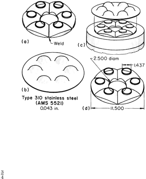
Fuel-nozzle swirl cups for high-performance turbojet engines were originally produced by welding six press-formed
sections of type 310 stainless steel, AMS 5521 (Fig. 17a). Forming the six sections was difficult, and the finished parts
were expensive. The rejection rate was also high.
Fig. 17 Original and improved methods of forming a fuel-
nozzle swirl cup for a turbojet engine. (a) Part formed
by original method; six press-formed sections welded together. (b) Partly drawn blank ready for rubber-
diaphragm forming. (c) Punch of six similar wedge-
shaped segments doweled into bottom plate, used for
rubber-diaphragm forming. (d) Swirl cup as formed by the rubber-diaphragm method an
d subsequently pierced
and trimmed. Dimensions given in inches.
Rubber-diaphragm forming in a Hydroform press was tried. This press formed the part from one blank 1.1 mm (0.043 in.)
thick by 324 mm (12 in.) in diameter. Less press force was used, and costs were reduced 50%.
Before forming, the blank was rough drawn (Fig. 17b) in a 1330 kN (150 tonf) hydraulic press to a depth of 35.6 mm
(1.40 in.), and its thickness was reduced to 0.99 mm (0.039 in.). After degreasing and annealing, the partly formed blank
was drawn in a 305 mm (12 in.) Hydroform press, using the punch shown in Fig. 17(c). The blank rested on a blankholder
mounted on a subbolster. Diametral clearance between punch and blankholder was a minimum of 50% of the work metal
thickness. The production rate was 30 pieces per hour.
After forming, six equally spaced 36.50 mm (1.437 in.) diam holes and a 63.50 mm (2.500 in.) diam center hole were
pierced in a 490 kN (55 tonf) mechanical press. The outside diameter was trimmed in a lathe after the part had been
pierced, annealed, and restruck. The completed workpiece is shown in Fig. 17(d).
Lubricants. The following example shows the importance of the lubricant and its application when the depth of draw is
near the limit for the rubber-diaphragm process.
Example 7: Use of Lubricant to Eliminate Tearing and Wrinkling in Severe Rubber-
Diaphragm Drawing.
The stepped cover shown in Fig. 18 represented the limit of forming severity for the rubber-diaphragm equipment that
was available. The material was 1.0 mm (0.040 in.) thick cold-rolled drawing-quality 1008 steel. The shell was 102 mm
(4 in.) deep and had a step in its outer contour. Attempts to draw the stepped shell in one operation in a Hydroform press
were not successful. Subsequently, two Hydroforming operations were developed in which the larger width of the cover
was drawn first, and then the narrower portion above the step was produced in a redrawing operation to complete the part.