ASM Metals HandBook Vol. 14 - Forming and Forging
Подождите немного. Документ загружается.

area on the leading end and the smaller flat area on the trailing end.
The position of the top roll is fixed, while the lower front roll is adjustable vertically to suit the thickness of the blank.
Optimal adjustment of the lower roll is important for gripping the stock and for minimizing the length of the flat areas on
the workpiece. The rear, or bending, roll is adjustable angularly (usually 30° off vertical), as shown in Fig. 2. Angular
movement of this roll determines the diameter of the cylinder to be formed.
All of the rolls are powered in most pinch-type machines. On some machines, however, only the two front rolls are
powered and the bending roll is rotated by friction between the roll and the work metal (Fig. 2). This arrangement is
usually satisfactory in forming medium-to-heavy stock to large diameters. However, when forming sheet or plate that is
thin or soft (or both) or when the diameter is large, the amount of friction is sometimes insufficient to rotate the bending
roll. This condition can result in a marred surface if the work metal is soft or has a bright mill finish (aluminum sheet, for
example).
A pinch-type machine can produce a more nearly true cylindrical shape than a pyramid-type machine because the work
metal is held more firmly. This results in smaller flat areas on the leading and trailing ends of the workpiece.
As shown in Fig. 2, the work metal is fed to the powered pinch rolls (front), which grip the plate and move it through the
machine. Forming begins when the work metal contacts the bending roll (rear) and is forced upward. As the forward
motion of the workpiece continues, a cylindrical shape is produced, except for the unformed flat area along the leading
end and a small flat area at the trailing end of the workpiece (Fig. 2). The width of the flat area on the trailing end usually
ranges from ½t to 2t (t, work metal thickness), depending on the design of the machine.
In most pinch-roll forming, one of two procedures is used to minimize flat areas. The most common method is to preform
both ends of the work metal in the machine. This is done by reversing the rotation of the rolls and feeding a short section
of the work metal from the rear, thus preforming one end. The work metal is then removed from the machine; the formed
section can be fed into the machine from the front, or it can be turned to the opposite unformed end and fed through from
the rear of the machine. This procedure eliminates most of the flat areas.
Another method is to preform the leading and trailing ends of the work metal in a press brake, hydraulic press, or joggling
press. However, this technique is seldom used, because it is usually more convenient to preform in the pinch-roll
machine.
On the other hand, preforming in a press brake or in hydraulic or joggling presses can sometimes save time in the rolling
machine, thus increasing the productivity of the machine. Additional advantages of a pinch-roll machine, as compared to
a pyramid-roll machine, are:
•
When all rolls are power driven, thinner sheets can be rolled, and cylinders can be formed to within about 50 mm
(2 in.) of the diameter of the top roll
• A given size of a pinch-type machine can roll a greater range of metal thicknesses because of the method of feed
• Greater dimensional accuracy can be obtained in one pass in a pinch-type machine than in a pyramid-
type
machine
The principal disadvantage of a pinch-roll machine is its unsuitability for rolling workpieces from angles, channels, and
other structural forms.
Shoe-Type Pinch-Roll Machines. One important modification of the conventional three-roll pinch-type machine is
the shoe-type machine, which uses the pinch principle and incorporates a forming shoe, as shown in Fig. 3. Because of
the relationship of the two front rolls and the forming shoe to the workpiece, the flat area becomes barely discernible
compared with the length of flat area obtained when rolling in a conventional machine (without preforming).
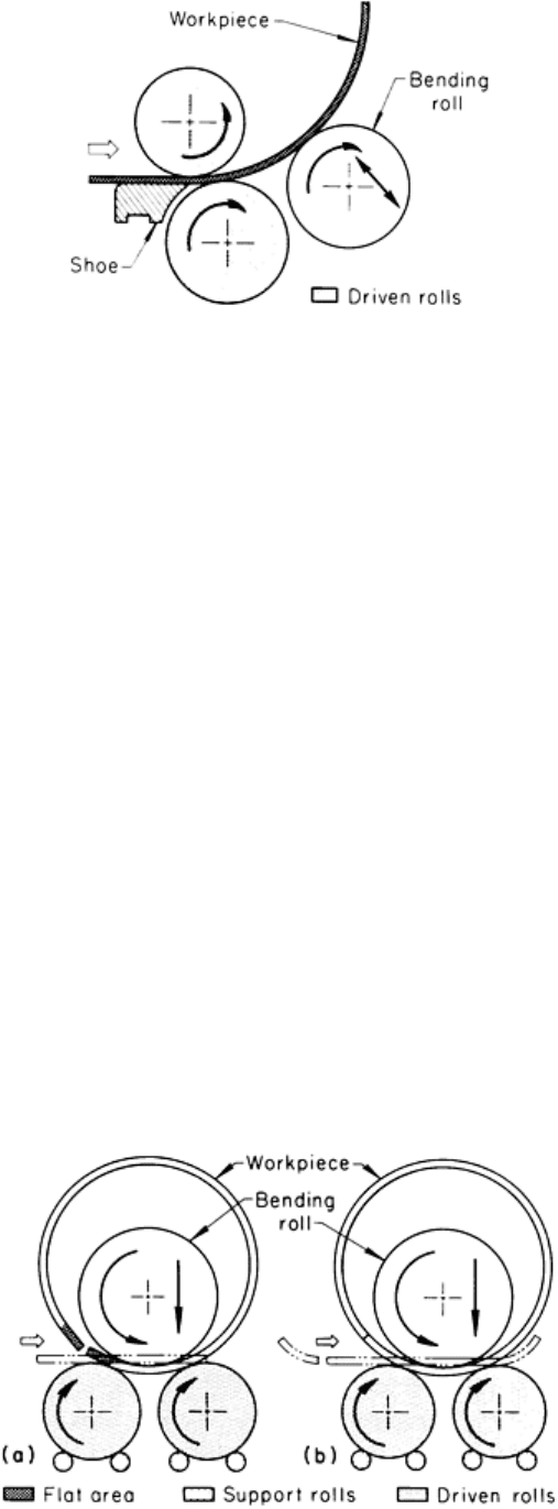
Fig. 3 End view of a cylindrical workpiece being rolled in a shoe-type machine with two powered rolls.
The shoe-type machine is often used to manufacture transformer cases and small tanks, such as jackets for hot-water
tanks. This type of machine can be completely automated; therefore, the work metal can be positioned on the table and
fed into the machine automatically. During the work cycle, the cylinder is formed and ejected by means of an ejector
mechanism and an automatically controlled drop end. Thus, a shoe-type machine is primarily a production machine that is
used where large quantities of identical workpieces are to be rolled. For this reason and because of the limitations listed
below, shoe-type machines seldom compete directly with conventional pinch-type machines:
• Thickness of the work metal is limited to 12 gage (2.657 mm, or 0. 1046 in.)
• Width of the sheet is limited to 1.83 m (72 in.)
• Shoe-
type machines are best adapted to the rolling of round cylinders; the rolling of ovals or obrounds is
impractical
• Shoe-type machines are applicable only to cold forming
Within their range of applicability, however, shoe-type machines can produce a rolled cylinder in about half the time
required in a conventional machine, primarily because preforming is not required with a shoe-type machine.
Pyramid-Type Machines. Figure 4 illustrates the arrangement of the rolls in a pyramid-type machine. The bottom
rolls are of equal diameter, but are about 50% smaller in diameter than the top roll. The bottom rolls are gear-driven and
are normally fixed; each roll is supported by two smaller rolls (Fig. 4). The top roll is adjustable vertically to control the
diameter of the cylinder formed. The top roll, which rotates freely, depends on friction with the work metal for rotation.
Backup rolls are not used on the top roll.
Fig. 4 Arrangement of rolls in a pyramid-type machine. (a) Entrance
of flat workpiece and shape of a nearly
finished workpiece, including the flat areas on the leading and trailing ends. (b) Similar, except that the

workpiece was prebent to minimize the flat areas on the ends.
As shown in Fig. 4, the work metal is placed on the bottom rolls while the top roll is in a raised position. The top roll is
then lowered to contact and bend the work metal a predetermined amount, depending on the diameter of the workpiece to
be formed. Machines are usually equipped with a device that indicates the amount of initial bend. Some machines use an
ammeter, which shows the amount of current used in forcing the roll downward. However, this device measures force
only; variables in the work metal can cause differences in the amount of bend for a given force.
As required bending force increases, machines are designed with rolls of larger diameter, and the distance between
centers of the bottom rolls increases. Bending forces are applied midway between the bottom rolls; therefore, less force is
needed for a given deflection, but less curvature is produced.
Because the top roll is adjustable, pyramid rolls can be used for forming irregular shapes by bolting dies to the top roll--a
technique that is not adaptable to pinch-type machines. In addition, plate, beams, angles, and other structural forms can be
straightened with greater ease because the bottom rolls are on the same elevation.
The top roll is an idler; therefore, there are definite limitations on the minimum thickness of work metal that can be rolled
(especially when forming large diameters). Adequate stiffness in the work metal is essential to provide enough friction to
rotate the top roll. The minimum thickness that can be rolled varies, depending on the specific machine and the work
metal composition.
Another disadvantage of the pyramid machine is the large flat areas that remain on both the leading and trailing ends of
the work metal. Because the workpiece must remain supported by the bottom rolls at all times, the ends of the work can
never get closer to the top roll than the distance between the points of tangency of the workpiece and the rolls. Therefore,
it is impossible to eliminate these flat areas by rolling (Fig. 4a).
To minimize flat areas when using pyramid machines, the usual procedure is to preform the ends to the desired radius in a
press brake or to roll an oversize blank, then trim the flat ends after. The shell can sometimes be returned to the rolls for
truing after the seam has been joined. Occasionally, a narrow shim is placed at the ends to increase the bend radius, but
care must be taken to avoid machine overload. The techniques used in forming with pyramid rolls make it more difficult
to achieve the accuracy that is obtainable with pinch-type rolls.
Capacity. Three-roll forming machines are rated by the manufacturer according to the maximum thickness and width of
low-carbon steel plate the machine can form at room temperature. Values are usually given for single-pass rolling, and
allowances are then made for multiple-pass rolling. For example, a machine rated at 19 × 3660 mm (¾ × 144 in.)
(thickness and width of plate, respectively) for work metal with a maximum tensile strength of 414 MPa (60 ksi) and
capable of rolling plate to a diameter of 2.44 m (96 in.) in a single pass can roll to a final diameter of 584 mm (23 in.) in
multiple passes if the top roll is no larger than about 368 mm (14½ in.) in diameter.
If plate thickness is increased to 25 mm (1 in.), the same diameter restrictions would apply, but the allowable plate width
would be reduced from 3.66 to 1.42 m (144 to 56 in.) because of the additional power required for the increased thickness
of work metal. At this point, another limitation may be encountered because the load imposed on the shorter surface area
can become excessive as the plate becomes narrower and thicker. On the other hand, assuming all other factors remain
constant, if plate thickness is reduced to 16 mm ( in.), the allowable width would revert to full capacity of the machine
(3.66 m, or 144 in.), but the rolled diameter could be reduced to 419 mm (16½ in.).
The maximum plate thickness that can be handled by this machine depends on the pinch opening and is rated by the
manufacturer of the machine. For example, some machines rated as described above can accommodate work 38 mm (1½
in.) thick, but for forming this thickness in a machine having the indicated capacity, the allowable plate width would be
reduced to 533 mm (21 in.) because of the above-mentioned factors. All of the above calculations also take into
consideration the limiting factor of roll deflection.
With all other conditions constant, power requirements increase according to the square of metal thickness. Therefore, the
power required for forming plate 50 mm (2 in.) thick is four times as great as that required for forming 25 mm (1 in.)
thick plate of the same width.

Three-Roll Forming
Selection of Machine
Selection between pinch-type and pyramid-type machines depends mainly on the shape of the starting form and of the
finished workpiece, the number of formed parts to be produced, accuracy requirements, and the cost. The pinch-type
machine produces more accurate workpieces, and it can be loaded and unloaded much faster than the pyramid-type
machine. Although both machines can produce shapes other than plain cylinders, the pinch type is capable of rolling a
wider range of thicknesses. However, the pyramid-type machine is often preferred for small quantities of varied work, as
in a job shop. Because of the wide space that can be obtained between the upper roll and the two lower rolls in a pyramid
machine, various types of dies and fixtures can be fastened to the upper roll, thus permitting channels, angles, and various
other structural shapes to be rolled or bent, either hot or cold.
Rolls
Rolls used in three-roll forming machines are machined from steel forgings having a carbon content of 0.40 to 0.50% and
a hardness of 160 to 210 HB. Plain carbon steel such as 1045 has often been used; when greater strength is needed, rolls
are forged from an alloy steel such as 4340. Because the modulus of elasticity is the same for all carbon and low-alloy
steels of medium carbon content, roll deflection for a given force will be the same.
Although the hardness range of 160 to 210 HB can be obtained by annealing, rolls with a microstructure obtained by
quenching and tempering or by normalizing and tempering are less subject to surface deterioration from spalling.
Therefore, the forged rolls are heat treated before being machined.
Roll diameter varies with the length and thickness of plate to be rolled. A typical top roll in a pinch-type machine, rated
for forming steel plate up to 64 mm (2 in.) thick and 3.66 m (144 in.) wide, would have a minimum diameter of 762
mm (30 in.). Journals for rolls of this diameter are approximately 432 mm (17 in.) in diameter.
Crowning of rolls to compensate for deflection is common practice. The amount of crowning is not necessarily the same
for all rolls in a given machine. For example, in some machines, the rolls are not all of the same diameter; under these
conditions, a roll that is smaller in diameter requires more crowning than a larger roll because the stress on all rolls is the
same. When a machine is used for both light and heavy work, it is usual to crown the rolls for average conditions and then
to use strips either at the center of the rolls to compensate for extreme deflection or at the ends to compensate for a lack of
deflection (see the section "Roll Deflection" in this article).
Roll Maintenance. The extreme pressures to which rolls are subjected cause them to work harden. Rolls used in
continuous production under high pressure sometimes elongate and reduce slightly in diameter. The amount of elongation
or reduction in diameter is seldom significant, although the ends of rolls may require trimming after long periods of use.
There is no standard practice for reconditioning rolls. In some plants, rolls that have been subjected to long periods of
severe service are trued by removing some or all of the work-hardened layer by turning. When required, the diameter is
built up by welding an overlay on the rolls and then finish turning them. On the other hand, some manufacturers
recommend that roll surfaces should never be turned. If the surfaces are spalled or otherwise damaged, any protruding
metal should be removed by grinding. Although indentations in the rolls are less likely to be harmful, they may mark
polished or clad surfaces. When rolling scaly plate, blowing away loose scale with an air lance is helpful in preventing
scale from indenting the rolls or the work metal.
Bearings and Lubricants. Bronze has been successfully used for main bearings and is sometimes specified by the
user. However, tin-base babbitt is superior to bronze for most applications and is used in most machines. Tin-base
bearings are more compatible with the relatively soft steel journals at the pressures and speeds involved, and their ability
to absorb particles of scale minimizes the possibility of scoring journals or bearings.
Extreme-pressure lubricants are recommended for the main bearings on all rolls, and a grade containing molybdenum
disulfide is especially desirable. Because environmental conditions are likely to vary considerably where three-roll

forming is done, the lubricant should have good pumpability over a range of temperatures. Extreme-pressure lubricants
are satisfactory for both cold and hot forming.
Three-Roll Forming
Preparation of Blanks
Blanks are usually cut to the desired size before forming. The length of plate (dimension of the work metal perpendicular
to the axes of the rolls) required to form a given shape is determined by measuring the mean circumference (or perimeter,
if the shape is other than a cylinder), which is the circumference taken at one half the distance between the inside
diameter and the outside diameter of the shape to be formed. This method of calculation is the one most generally used in
both the cold and hot forming of plate.
Allowance for Shift in Neutral Axis. When greater accuracy is required, the more exact location of the neutral axis
is considered when computing the blank, particularly if heavy plate thicknesses are involved. The neutral axis is the
boundary between metal in tension and in compression and is usually one-quarter to one-half the thickness of the metal
being bent, as measured from the inside of the bend. The exact location of this axis varies to some extent with the bend
radius and the mechanical properties of the metal.
During cold forming, the neutral axis shifts inward from the mean by about 26% of the plate thickness. Therefore, for a
457 mm (18 in.) ID cylinder, rolled from 13 mm (½ in.) thick plate, the mean circumference is about 147.6 mm (58.12
in.), and for a 26% shift, the circumference at the neutral axis becomes 145.5 mm (57.30 in.). For a 457 mm (18 in.) ID
cylinder of 6.4 mm (¼ in.) thick plate, the mean circumference is 145.6 mm (57.33 in.), and with a 26% shift, it changes
to 144.6 mm (56.93 in.); the amount of shift is about one-half that for the 13 mm (½ in.) thick plate. Therefore, the shift of
neutral axis is usually disregarded for plate thicknesses less than 13 mm (½ in.) except where greater accuracy is required.
In cold forming, the length of the blank is calculated by using a radius that is determined by subtracting 26% of the plate
thickness from the mean radius or by adding 24% to the inside radius. When dimensional requirements are stringent,
similar allowances are made for shift of the neutral axis and for thermal expansion in the hot forming of thick plates (75
to 152 mm, or 3 to 6 in.) at 870 °C (1600 °F).
Cutting of blanks can be done by shearing, if shearing equipment is available for the width and thickness of the work
metal. Gas cutting is commonly used for preparing blanks that are too thick for shearing. Additional information is
available in the articles "Shearing of Plate and Flat Sheet" and "Thermal Cutting" in this Volume.
Edge Preparation. The cut edges of any plate (high-strength steel, in particular) can be a serious problem because of
cracking during cold forming, which is cause for rejection of the workpiece. When plate is sheared, the edges are rough
and often have surface cracks. Gas cutting usually produces smoother edges, but the edges of gas-cut steel plate will
frequently be hardened in cooling from the cutting temperature. Therefore, nucleation sites for cracks are likely to be
present from either method of cutting.
The danger from cracking caused by rough edges increases as plate thickness increases and the finished diameter of the
cylinder decreases. Because the plate surface that forms the outside diameter of the cylinder is in tension during forming,
cracks propagate from edges, which are in tension.
On plate 25 mm (1 in.) or more in thickness, the edges indicated in Fig. 5 should be removed before cold forming. This is
not required before hot forming. Usual practice is to employ a chipping hammer and then a portable grinder to smooth the
edges. The amount of metal removed is usually negligible, and a slight bevel on the critical edges is sufficient. If a
substantial amount of metal is to be removed, allowance must be made for it when calculating the dimensions of the
blank.
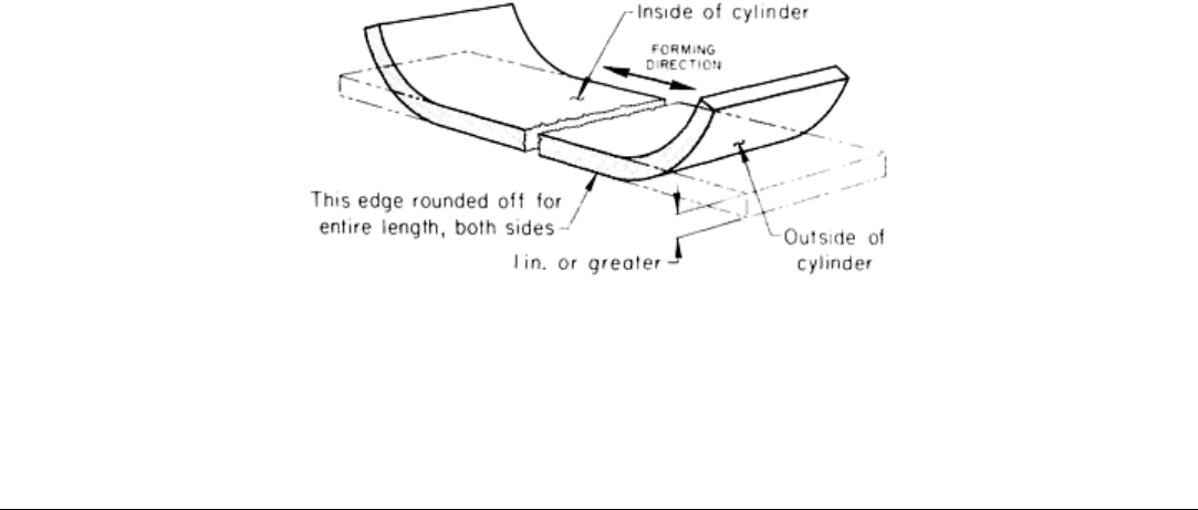
Fig. 5 Sheared or gas-
cut blank, showing where metal should be removed from edges before cold forming, to
reduce susceptibility to cracking.
Three-Roll Forming
Cold Versus Hot Forming
Because cold forming involves fewer problems and is less costly than hot forming, it is preferred practice to form
workpieces at room temperature. In hot forming, dimensional accuracy is more difficult to control, and cost is
significantly increased by:
• Heating the blank
• Handling both the blank and the workpiece while the metal is hot
• The necessity for restoring acceptable surfaces by pickling, blast cleaning, or other surface treatment
• The accelerated rate of deterioration of rolls and other equipment because of contact with hot metal
Forming Capacity. When carbon or low-alloy steel is heated, tensile strength decreases and formability increases.
Heating the work metal therefore extends the usefulness of a roll-forming machine. For example, a 3 m (10 ft) long pinch-
type machine with 495 mm (19½ in.) diam rolls can form a 3.66 m (144 in.) diam cylinder from 64 mm (2½ in.) thick by
622 mm (24½ in.) wide plate at room temperature in one pass (assuming the work metal has tensile strength of 410 MPa,
or 60 ksi, at room temperature). With all other conditions remaining constant, by heating the work metal to a temperature
high enough to reduce the tensile strength to 70 MPa (10 ksi) or lower, the width of the plate (measured parallel to the roll
axes) can be increased to 2.1 m (82 in.) and rolled in one pass, using the same amount of power needed for rolling plate
622 mm (24½ in.) wide at room temperature. To reduce the tensile strength of low-carbon steel and to obtain optimal
formability, the usual practice is to heat the steel to 870 °C (1600 °F).
Similarly, the size of machine described above is capable of cold forming a 3.66 m (144 in.) diam cylinder from 44 mm
(1¾ in.) thick by 1.5 m (60 in.) wide low-carbon steel plate in one pass. Under the same conditions, except for heating to
870 °C (1600 °F), the thickness of the plate can be increased to 70 mm (2¾ in.).
One method of evaluating the difference in formability between cold and hot rolling is to measure the force required to
form a given plate. This is done on pyramid-type rolls by measuring, in terms of amperage, the downward force on the
upper roll and the force required to rotate the powered rolls (Fig. 6). The following example demonstrates the difference
in current flow, number of passes, and time needed for the cold and hot forming of similar cylinders.
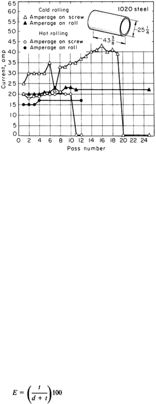
Fig. 6
Comparison of current flow (proportional to force) measured on screw and rolls during cold rolling and
during the rolling of 44 mm (1¾ in.) thick plate preheated to 870 °C (1600 °F). Dimensions given in inches.
Example 1: Cold Versus Hot Forming of 44 mm (1¾ in.) Thick Steel Plate.
A pyramid-type machine was used to produce 641 mm (25¼ in.) ID by 1.1 m (43⅜ in.) long cylinders from 1020 steel
blanks 44 mm (1¾ in.) thick by 1100 mm (43⅜ in.) wide by 2145 mm (84½ in.) long. When forming was done at room
temperature, 25 passes were required with current flow on the upper roll (screw) and power rolls as shown in Fig. 6.
Rolling time was 40 min per cylinder. When blanks were heated to 870 °C (1600 °F) and finished at 565 °C (1050 °F),
the number of passes was reduced to 12 and rolling time to 11 min per cylinder. Current flow was also reduced, as shown
in Fig. 6.
Hot Forming Formability Problems. The technique described in the preceding example for increasing the effective
capacity of equipment by hot forming does not apply to all metals, and the amount of decrease in tensile strength varies
considerably among carbon and low-alloy steels. For example, heat-resistant alloys, by definition, resist the softening
effect of heat, and many of these alloys precipitation harden in the temperature range that would be used for the hot
forming of carbon steel (see the article "Forming of Heat-Resistant Alloys" in this Volume). Magnesium and titanium
alloys are usually formed at the same elevated temperature used to form the same alloy by other methods (see the articles
"Forming of Magnesium Alloys" and "Forming of Titanium and Titanium Alloys" in this Volume). Copper and aluminum
alloys are usually formed at room temperature. However, alloys 7075 and 7079, as well as some other precipitation-
hardening alloys, must be formed within 24 h after solution treatment. If forming cannot be done within this length of
time, the work metal must be stored at -12 °C (-10 °F) to prevent precipitation hardening (see the articles "Forming of
Aluminum Alloys" and "Forming of Copper and Copper Alloys" in this Volume).
Maximum Elongation. In many applications with steel, hot forming is mandatory regardless of the capacity of
available forming equipment. Common practice is to compute a maximum elongation in the outer surface for cold
forming, as determined by:
(Eq 1)
where E is the percentage of elongation in the outer surface of the cylinder, d is the inside diameter of the cylinder (in
inches), and t is the plate thickness (in inches). For example, for a cylinder having an inside diameter of 1.45 m (57 in.) to
be formed from 75 mm (3 in.) thick steel plate:

(Eq 2)
Elongation of more than 5% (determined by Eq 2) is seldom permitted for cold forming, and the maximum is often 3.5%.
If the maximum permissible elongation was 3.5% in the above example, either the minimum cylinder diameter would be
near 2.11 m (83 in.) or plate thickness would have to be reduced before cold forming would be permitted. Maximum
elongation is established by the user of the formed product, and hot forming is used when specifications cannot be met by
cold forming.
Combination Hot and Cold Forming. A combination of hot and cold forming is sometimes advantageous and
permits elongation requirements to be met. For example, in forming the 1.45 m (57 in.) diam cylinder described above,
one procedure is first to hot form the 75 mm (3 in.) thick plate to a circular segment of about 2.29 m (90 in.), allow the
workpiece to cool to room temperature, and then clean and finish form at room temperature. This procedure makes it
possible to meet more severe elongation requirements and to retain some of the advantages of cold forming, such as
greater accuracy.
Three-Roll Forming
Hot-Forming Temperatures for Steel
Carbon or low-alloy steel plate is commonly heated to 870 °C (1600 °F) for hot forming after normalizing at the mill.
However, plate in the as-rolled condition is less costly. The as-rolled steel is normalized while it is being heated for
forming and cooled during forming. In such an operation, the steel is heated to 900 to 925 °C (1650 to 1700 °F), instead
of to 870 °C (1600 °F), before forming.
Finishing temperature is critical for some steels, especially the plain carbon grades, because of the blue-brittle
temperature range. It is generally recommended that the finish-rolling temperature should be 565 °C (1050 °F) or higher.
If the workpiece cannot be completely formed before it cools to 565 °C (1050 °F), it should be removed from the machine
and reheated.
Warm forming is often used when forming requirements are too severe for room temperature and when heating to the
conventional hot-forming temperature cannot be permitted because the mechanical properties of the steel would be
impaired. A notable example is the forming of quenched-and-tempered grades of high-strength low-alloy steel. Common
practice is to heat these steels no higher than the temperatures at which they were tempered and then form at once.
Three-Roll Forming
Power Requirements
The power required to form a given cylinder on three-roll equipment depends on the strength of the work metal, plate
thickness, plate width, finished diameter of the cylinder, number of passes used, and temperature (hot or cold forming).
Strength of the work metal, plate thickness, and plate width (measured parallel to the roll axes) determine the diameter
of a cylinder that can be formed in a given machine. The curves in Fig. 7, for a 3.1 m (10 ft) long pinch-type roll machine
with 483 mm (19½ in.) diam rolls, represent combinations of maximum plate thickness and width that can be rolled at
room temperature into cylinders of 3.66 m (144 in.) in diameter or larger in a single pass. The significant influence of the
strength of the steel is evident from Fig. 7. For example, 38 mm (1.5 in.) thick low-carbon steel plate of 410 MPa (60 ksi)
tensile strength can be rolled into 3.66 m (144 in.) diam cylinders in one pass in widths up to 3.05 m (120 in.) in this
machine. Under similar conditions, the width of 38 mm (1.5 in.) thick high-strength low-alloy steel that can be formed to
the same cylinder diameter is restricted to about 56 mm (22 in.) (Fig. 7). The machine used was rated at 67 mm (2 in.)
by 3.05 m (120 in.).
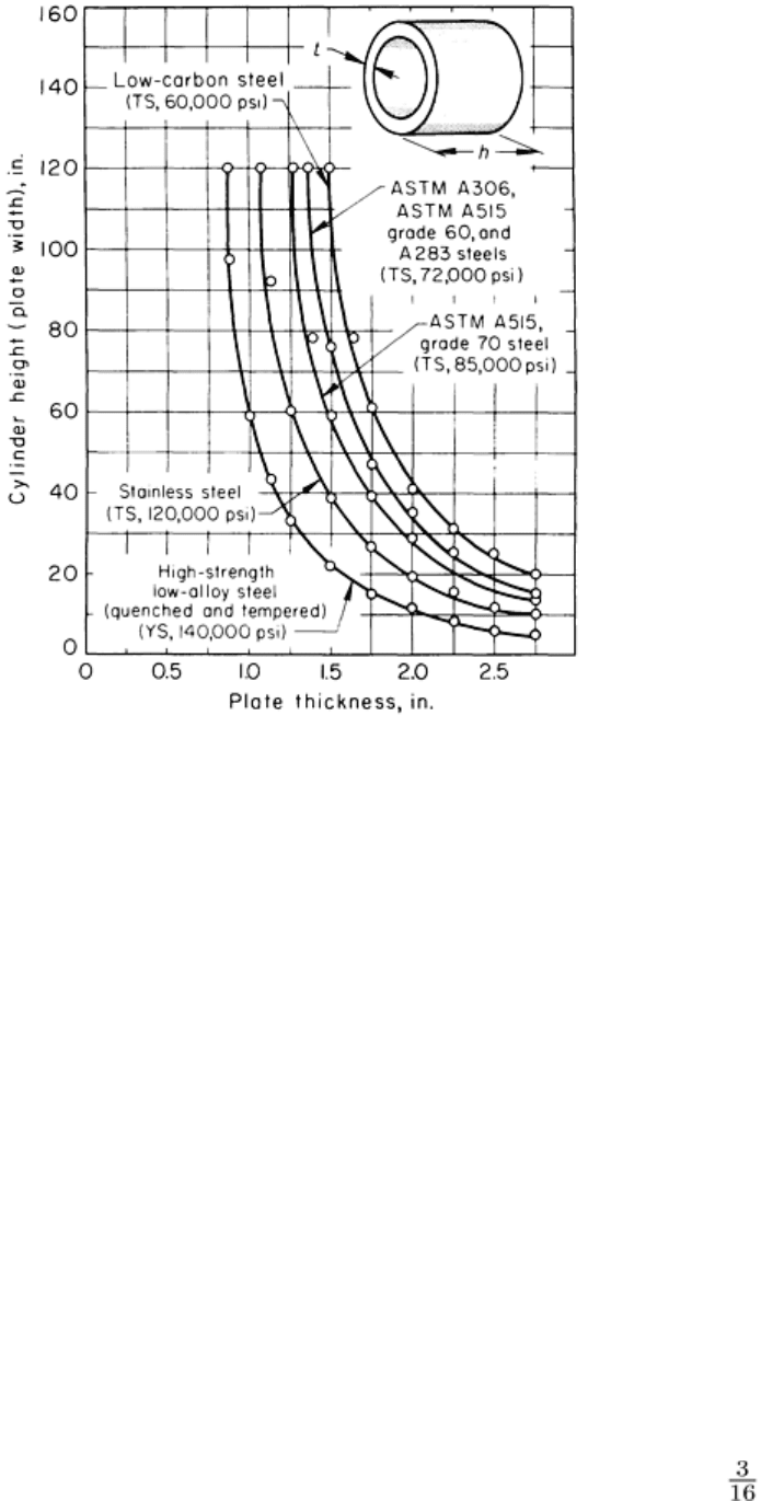
Fig. 7 Interrelationship of cylinder height (h), thickness (t
), and work metal strength for forming in a single
pass in a pinch-type roll machine at room temperature.
Work Hardening. Most metals are susceptible to strengthening by cold work (work hardening), although the extent to
which metals are affected varies widely among the various compositions. Of the steels commonly processed by three-roll
forming, those of low carbon content, such as 1010, are least susceptible to work hardening and seldom present any
serious problems. As carbon or alloy content increases, the rate of work hardening increases.
For metals that work harden rapidly, power consumption increases as forming proceeds. Eventually, the machine is
overloaded, or the work metal fractures.
Intermediate annealing must be used when work-hardenable metal is severely formed. For steel, full annealing is
usually recommended. Process (subcritical) annealing is sometimes used. However, process annealing alternated with
cold work is likely to result in excessive grain growth and subsequent poor formability, despite the hardness.
Cylinder Diameter. With other conditions constant, power requirements increase as cylinder diameter decreases when
the cylinder is completely formed in one pass. However, the use of two or more passes (up to 12 is not uncommon)
permits the rolling of smaller-diameter cylinders without increasing machine size. For example, Fig. 7 shows that 38 mm
(1.5 in.) thick by 3.05 m (120 in.) wide plate of low-carbon steel can be formed into a cylinder 3.66 m (144 in.) in
diameter in one pass on a given machine. By using 10 or 12 passes, cylinders as small as 65 mm (25½ in.) in diameter
have been formed from the maximum thicknesses shown in Fig. 7. For plate thickness of 30 mm (1 in.) or less,
cylinders as small as 55 mm (21½ in.) in diameter can be formed in multiple passes.
Similarly, for carbon steel having a tensile strength to 590 MPa (85 ksi) and stainless steel to 830 MPa (120 ksi), any of
the plate thicknesses shown in Fig. 7 can be rolled to cylinders as small as 70 mm (27½ in.) in diameter. For steels having
a tensile strength of about 500 MPa (72 ksi), plate thicknesses of 28 mm (1 in.) or less can be rolled to cylinders 56
mm (22 in.) in diameter, using the multiple-pass procedure. The plate thickness limitations for rolling 56 mm (22 in.)
diam cylinders then decrease to 26 mm (1 in.) (maximum) for steel with a tensile strength of 590 MPa (85 ksi) and to
21 mm ( in.) for stainless steel with a tensile strength of about 830 MPa (120 ksi).
Power requirements for quenched-and-tempered high-strength low-alloy steel (970 MPa, or 140 ksi, in Fig. 7) are high,
and there is an increased probability of cracking. Suggested limits for maximum plate thickness and minimum cylinder
diameter for multiple-pass rolling, regardless of power, are:
Maximum
plate thickness
Minimum
cylinder diameter
mm in. mm
in.
25 1 1170
46
19
889
35
13
826
32
9.5
775
30
6.4
711 28
Temperature. The limitations imposed by steel composition and other factors shown in Fig. 7 are markedly changed
when the work metal is heated (see the section "Cold Versus Hot Forming" and Example 1 in this article). However, it is
not always possible to use hot forming--for example, for quenched-and-tempered high-strength low-alloy steel (see the
section "Warm Forming" in this article).
Three-Roll Forming
Forming Small Cylinders
The cold forming of small cylinders by the three-roll process requires extra care, especially when the diameter of the
cylinder to be formed is near that of the rolls. The rolling of cylinders having an inside diameter of less than 50 mm (2 in.)
more than the outside diameter of the roll is not generally recommended. However, a skilled operator, using special care,
can form cylinders within 38 mm (1½ in.) in diameter in a pinch-type machine.