ASM Metals HandBook Vol. 14 - Forming and Forging
Подождите немного. Документ загружается.

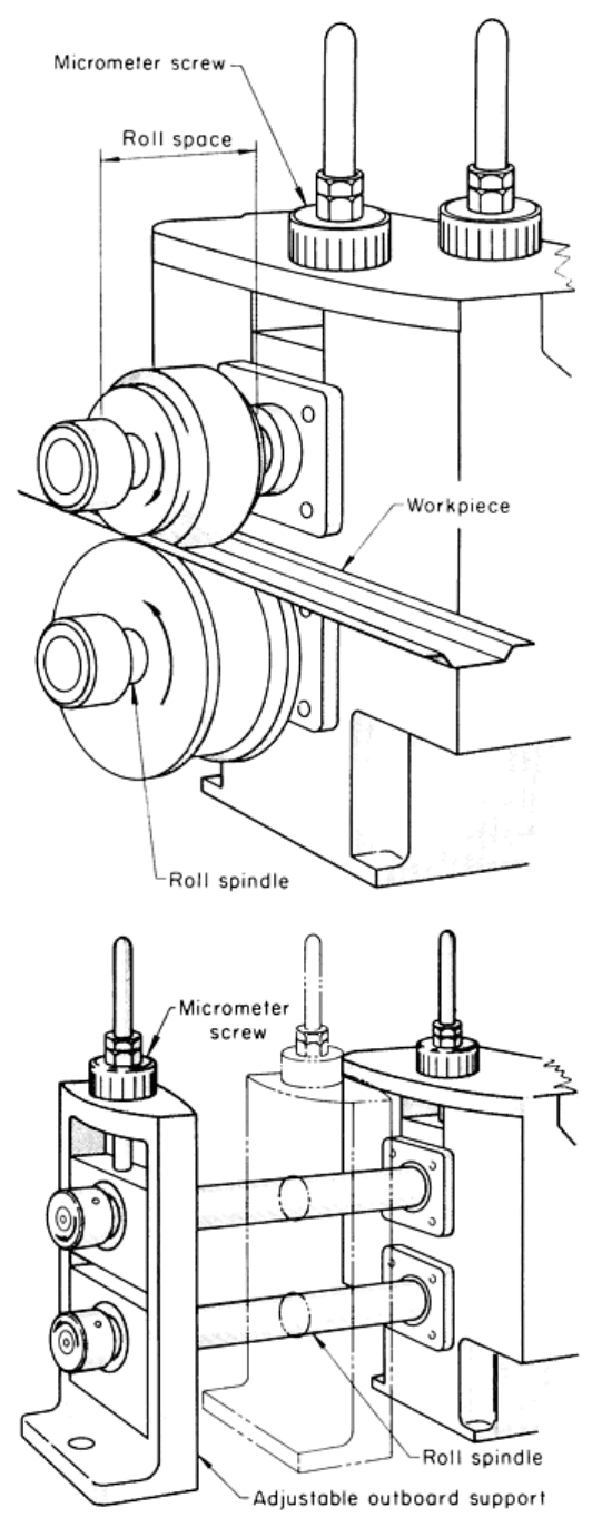
Fig. 2 Two basic machine concepts for contour roll forming. (top) Inboard-type machine. (bottom) Outboard-

type machine.
Outboard machines (Fig. 2 bottom) have housings supporting both ends of the spindle shafts. The outboard housing is
generally adjustable along the spindles, permitting shortening of the distance between the supports to accommodate the
roll forming of small shapes of heavy-gage material. This adjustment also permits the machine to be used as an inboard
type of machine when desired. Outboard machines can be readily designed to accommodate any width of material by
making the spindle lengths suit the material width and then mounting the individual units and spindles on a baseplate of
suitable width. This type of machine is built with spindle sizes ranging from 38 to 102 mm (1½ to 4 in.) diam and with
width capacities up to 1830 mm (72 in.).
Generally, for roll forming material more than 5 mm ( in.) thick, machines are constructed so that both top and bottom
shafts can be removed by lifting them vertically from the housings after the housing caps have been removed. This
permits rolls to be mounted on the shafts away from the machine, an important consideration when heavy rolls are being
handled. This type of machine is built in spindle sizes ranging from 50 to 380 mm (2 to 15 in.) in diameter.
Station Configuration. As was previously mentioned, a typical contour roll forming machine consists of several
individual forming units mounted on a common baseplate. The manner in which the forming units are mounted
determines to a great extent the type of shapes that are formed on the machine.
Single-duty machines are built and designed for a one-purpose profile or for one particular set of roll tooling, and are
not normally designed for convenient roll changing. This machine is generally used for long production runs, and its cost
is low in comparison to the other styles.
Conventional (standard) machines are more versatile than single-duty machines because the outboard supports are
easily removed. This facilitates roll changes, making conventional machines suitable for a variety of production
requirements.
To change the tooling, the top and bottom spindle lock nuts are removed and the out-board housing is pulled off the
spindles. The tooling can then be removed and replaced with the desired profile.
Side-by-side machines (Fig. 3) are designed for multiple-profiled tooling and provide the flexibility of having more
than one set of roll tooling mounted on the spindle shaft at the same time. Generally, this type of machine is limited to
two sets of rolls at a given time, but there can be up to three or four sets of rolls when small profiles are being run in
production. Changeover from one production profile to another is accomplished by shifting the machine bed to the
desired profile. The main advantages of the side-by-side configuration are low initial investments, fast tooling change,
and reduced floor space requirement. Roll wear, however, can create problems because one set cannot be reground
without regrinding the others at the same time. Adjusting for material variations can also be a problem.
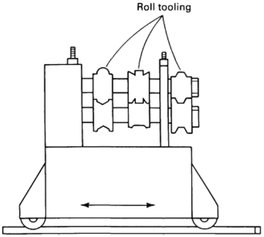
Fig. 3 A side-by-
side contour roll forming machine, which allows forming of several different profiles on the
same machine.
The double-high machine configuration consists of one set of roll tooling mounted on its own roll shafts and
housings at one level on the bed frame, and a second complete set of roll tooling and housings mounted at a different level
on the same frame. This particular type of machine is used in the metal building industry for forming building panels up
to 1520 mm (60 in.) wide.
The rafted machine configuration resembles the single-duty and conventional configurations, because each
configuration has housings and spindle shafts with one particular set of roll tooling mounted on it. However, the rafted
configuration has several roll-forming units mounted on rafts or subplates that are removable from the roll-former base.
During tool changeover, the individual rafts are removed from the base, and the replacement rafts with the roll-forming
units and tooling are installed. On a typical 16-stand roll-forming machine, there are four sets of rafts containing four
forming units each.
Double-head machines are designed and constructed with two separate sets of housings and roll shafts mounted so
that they face one another. Each housing is mounted on an adjustable plate mechanism to allow the housing to be shifted
for a change in overall width while at the same time maintaining the same profile for the edge formation.
This type of machine is very popular in the shelving industry, in which large, flat panels are rolled on a production basis
and the panel widths change regularly. A disadvantage of this type of machine is that it does not lend itself to forming the
center of the panel. Two of these machines, connected by an automatic transfer mechanism, are used to form the four
edges of a shelf; the first machine forms the two long edges, and the second machine forms the two end configurations.
Drive Systems. The five basic methods used to drive roll forming units are chain drive, spur gear drive, worm gear
drive, square gearing, and universal drive.
A chain drive consists of a sprocket attached to the individual roll forming unit and connected to the main drive by
means of a roller chain. This is accomplished using a continuous roller chain, with one long chain driving each unit, or a
shorter chain connected to each individual unit. This drive system is inexpensive and allows flexibility in the construction
of the machine.
A spur gear drive consists of a continuous train of spur gears mounted at the rear end of each spindle shaft. Idler gears
are positioned between each unit to transfer the drive equally to all the units.

A worm gear drive is very similar to the spur gear drive. However, instead of using the idler gear to transfer the drive
to each unit, an individual worm gear box is mounted on the bottom spindle of each unit. The worm gear boxes are
coupled in line, which permits the machine designer to spread out the horizontal centers of each roll forming station
without being concerned about properly meshing the gear train to the idler gear.
Square gearing also incorporates both spur gears and a worm gear. This type of gearing permits a vertical adjustment
of the upper spindle and allows use of a wide range of roll diameters.
Universal drive eliminates the need for any spur gearing or roller chain and sprocket drives. It consists of a series of
worm-driven gear boxes with top and bottom outputs that transfer the power source to the individual shafts through a
double-jointed universal coupling. On certain applications, only the bottom spindle is driven. This drive system is
generally used with rafted-style machines to permit quick tool changeover. Simplicity of design and minimal maintenance
are two important advantages of this drive system.
Machine Selection. Several factors must be taken into consideration when selecting a machine to be used in a roll
forming operation. These include load capacity, section size and shape, and roll changeover.
Load Capacity. The type and thickness of the material being formed determine to a large extent the load capacity that a
given forming machine is required to produce. If material type and thickness change, it is best to select a machine that can
provide the additional capacity.
In forming material up to 1.5 mm (0.060 in.) thick, a machine with 38 mm (1½ in.) diam spindles should be used as long
as the part is not too wide. A machine with 50 mm (2 in.) diam spindles can be used for forming material thicknesses up
to 2 mm (0.080 in.). As the material thickness increases, the diameter of the spindles must also increase to provide
strength to create the pressure required to do the forming. Center distances must be increased as the size of the part shape
and the movement of material between forming stations increases. These distances are usually determined by the machine
builder.
Section Size and Shape. Wide roll-formed sections require wide roll spaces. To support the pressure of the rolls, the
spindle shafts must be large enough in diameter to prevent shaft deflection during forming. The distance between the
centerline of the bottom spindle and the machine bed determines the maximum roll diameter and hence the maximum
section depth.
The more complex the shape of the section being formed, the greater the number of passes (pairs of rolls) required to roll
form the section. It is best to select a machine that provides the flexibility of adding or subtracting pairs of rolls in
accordance with the part design.
Roll changeover can be costly and time consuming, because material variations may require different roll pressure
settings. When several part configurations must be run on one machine, it is best to select a machine that permits the
tooling to be changed quickly. If only two or three profiles are run, the side-by-side and the double-high machines are
possible selections; the changeover can be performed quickly without losing valuable production time. Another machine
to consider is the rafted machine.
Contour Roll Forming
Auxiliary Equipment
In addition to the machines that do the roll forming, several other pieces of equipment are usually required for production
operation. Stock for roll forming is usually received in coils; thus, an electric hoist on an overhead track is needed to lift
coils from skids and transfer them to a cradle or reel (another piece of auxiliary equipment). Also equipment for welding
the end of an expended coil to the lead of the next one, an entrance guide, intermediate guides, a straightening device, and
cutoff equipment may be needed.
Stock reels should be equipped with an expandable arbor to fit the inside diameter of the coil, and with a friction drag.
Stock reels incorporating these features are commercially available in a wide range of coil capacities (see the article
"Presses and Auxiliary Equipment for Forming of Sheet Metal" in this Volume).

The friction drag is necessary to prevent the coil stock from overrunning onto the floor in the event of a sudden stoppage
of the roll forming equipment. In the simplest type of motor-driven stock reel, a dancer arm and roll ride the stock in a
loop-detector arrangement, which starts and stops the motor as required, supplying stock at the average rate used by the
roll former. Stock speed is matched approximately by adjusting a variable-pitch sheave to prevent too-frequent stopping
and starting of the alternating current drive motor. This type of control on the stock reel provides acceptable results for
most applications. More elaborate controls can be used, such as a direct current motor drive with feedback control to
match stock speed with machine speed. Elaborate controls are expensive and should not be considered unless they are
needed to meet special workpiece requirements.
Stock reels are available with a swivel base and two arbors. A coil may be positioned on one arbor while the first coil is
being used, thus reducing change time. This arrangement is advantageous when coils are relatively small and production
requirements are high, because time consumed in changing coils can become a substantial portion of the total production
time.
Welding Equipment. Thread-up time can be eliminated by manually welding the end of each expended coil to the
leading end of the next one. For stock thickness of 1.6 mm ( in.) or more, a semiautomatic welder can be placed in the
line. Regardless of the welding method used, any appreciable flash must be removed before the welded joint reaches the
first roll station. Provision can be made to remove flash by installing a grinder similar to a band saw blade grinder. More
information on combined roll forming and welding operations is available in the section "Tube and Pipe Rolling" in this
article.
Entrance guides positioned in front of the first forming station ensure correct alignment of the work metal entering the
starting rolls. This is particularly desirable when the part being formed is asymmetrical in the first station because the
stock could climb or shift to one side without guides. The simplest form of entrance guide consists of a flat plate with a
channel milled to the proper width and depth to accept the strip at its maximum tolerance, plus a simple, removable lid to
hold the stock in place. The mounting for this guide should permit adjustment vertically and laterally.
When wide variations in stock width are encountered, a self-centering, parallel-rule entrance guide is preferred. This
guide is constructed like a navigator's parallel rule, with the crossbars pivoted and mounted at their centers with a spring,
causing the side bars or rules to close on the stock under spring load.
Stock drags are occasionally used to place a slight tension on the stock and to cause it to feed more uniformly through the
first few stations. The simplest form consists of two pieces of hardwood. The stock is clamped between the wooden
members, which butt against the entrance guide, thus providing enough friction to keep the stock under tension. The
amount of tension can be regulated by the clamping force on the wooden members.
Guides between roll stations facilitate entrance of the partly formed stock into the next station. In theory, if rolls are
properly designed, guides between stations are unnecessary, because each set of rolls should accept the cross section from
the preceding set of rolls. In practice, however, because of such factors as cost, lead time, and availability of space or
equipment, the number of roll stations is often fewer than the ideal number; this necessitates more forming in each station
than is consistent with the best practice. Therefore, the use of guides between stations helps to compensate for this lack of
additional stations, and to minimize springback.
Generally, guides between stations are only required to contact the critical points of the work metal, not the entire
contour. Regardless of their shape, guides should be designed with removable top portions to facilitate threading.
Various metals may be used for guides, depending on the end-use of the workpiece. For the areas contacting the moving
workpiece, hardened steel (usually, case-hardened low-carbon steel) is preferred from the standpoint of guide life.
However, when workpiece finish is critical and hardened steel guides are likely to scratch the surface, bronze or
aluminum guides are used. For some work, hard chromium plating of guides minimizes damage to workpiece surfaces
and still provides acceptable guide life. Guides can be replated when the plating becomes worn.
Straightening Equipment. Usually it is necessary to straighten the workpiece after it leaves the final roll station. This
is done by standard straightening guides attached to the machine beyond the last set of rolls, or by special devices
designed for individual applications.

Straightening guides are usually adjustable vertically and laterally; the most versatile types can be swiveled in either
elevation or azimuth and can also be rotated about an axis. Most straighteners employed for contour roll forming are
either of the roll type or the shoe type.
A roll straightener consists of multiple rolls (individually adjustable) arranged to contact the stock in selected areas. A
shoe straightener consists of one or more shoes, usually made of bronze, properly fitted to the contour and adjustable in at
least one direction that will crimp the stock to correct for sweep or twist.
There are also applications in which a sweep (curve) is deliberate and desired. A sweep guide is similar to a straightening
guide, and a straightening guide often can be adjusted to give the required sweep in a constant radius. For more detailed
information on straightening equipment, see the articles "Straightening of Bars, Shapes, and Long Parts" and
"Straightening of Tubing" in this Volume.
Cutoff Equipment. Because most contour rolled products are made from coil stock, a system of cutting the formed
shapes to length must be provided. There are several types and sizes of flying-shear cutoff machines.
The sliding-die cutoff machine is most commonly used. The action of this machine is similar to that of a punch press,
although construction of the machine differs. The flywheel and clutch are placed below the bed, with the ram posts
passing through the bed. Gibs are provided in the bed and ram to accept a gibbed die and a punch holder that permits
linear movement of the die to match work metal speed during the cutoff cycle.
Contour Roll Forming
Tooling
Tooling used in roll forming includes the forming rolls and the dies for punching and cutting off the material. Tube mills
require some additional tooling to weld, size, and straighten the tubes as they are produced on the machine; the needed
tooling is discussed in the section "Tube and Pipe Rolling" in this article.
Forming Rolls
The rolls are the tools that do the actual forming of the material as it moves through the roll forming machine. Several
factors must be considered when designing the rolls to form a particular part. These include the number of required
passes, the material width, the "flower" design, the roll design parameters, and the roll material. Flower is the name given
to the progressive section contours, starting with the flat material and ending with the desired section profile.
Number of Passes. The roll forming of material into a desired final shape is a progressive operation in which small
amounts of forming are performed at each pass or pair of rolls. The amount of change of shape or contour in each pass
must be restricted so that the required bends can be formed without elongating the material. Too few passes can cause
distortion and loss of tolerances; too many passes increase the initial tooling cost.
Generally, the number of passes depends upon the properties of the material and the complexity of the shape. Other areas
to consider are part width, horizontal center distance between the individual stations, and part tolerances. The number of
passes must be increased as the tolerances of the shape become tighter.
Material. Material thickness, hardness, and composition all affect the number of passes required to achieve a desired
shape. As the thickness of the metal increases, the number of passes required to form the material increases. Steel that has
a high yield strength should be overformed approximately 2° and then brought back to finish size on the final pass.
Overforming compensates for springback that is encountered when materials having high yield strengths are formed.
Material that is coated or that has a polished surface generally requires more passes than does uncoated material. Precut
material may also require more passes so that the rolls can pick up the leading end of each section.
Shape complexity is determined by the number of bends and the total number of degrees that the formed part must be
bent. It is also influenced by the symmetry of the part design. The forming angle method is a rule of thumb which roll
designers use to determine the approximate number of passes.
On simple shapes, a forming angle of 1 to 2° is recommended. This forming angle is based on the amount of bending
performed for every inch of distance between station centers (horizontal center distances). The minimum forming length
for a single bend is determined by multiplying the height of the desired section by the cotangent of the forming angle.
This length is then divided by the distance between station centers on a given machine, to determine the approximate
number of passes. For multiple bends, the number of passes must be determined for each bend and then, after the
formation of bends have been combined where possible, the approximate number of passes can be determined.
Horizontal Center Distance. If the machine on which the section must be run is predetermined, the specifications and
limitations of the machine will have a bearing on the number of passes required. The distance between stations (horizontal
center distance) may dictate more stations if that distance is too short. The total distance from flat material to finished
section is more critical than the number of stations, because undue stresses are created by forming too fast.
Strip Width. The width of strip required to produce a given shape is determined by making a large-scale layout,
dividing it into its component straight and curved segments, and totaling the developed width along the neutral axis. The
outside profile and the neutral axis of each curved segment can usually be treated as circular arcs. Also, for bends having
an inside radius of up to about twice the stock thickness in low-carbon steel, the neutral plane or axis is located
approximately one-third of the distance from the inside surface to the outside surface at the bend.
Developed width, sometimes termed bend allowance, is the amount of material required to form a curved section of a
particular shape properly. The two methods for calculating developed width described in this section use general
equations and can be employed for all shapes. The equations given are applicable when low-carbon steel is formed; for
less-formable materials, values should be increased.
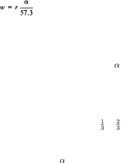
Method One. Using this method, developed width w is calculated as follows:
(Eq 1)
If the inside bend radius is less than two times the material thickness, then:
r = r
i
+ 0.4t
(Eq 2)
where w is in millimeters (inches), r is the bend radius in millimeters (inches), is the angle (in degrees) through which
the material is bent, r
i
is the inside bend radius in millimeters (inches), and t is the metal thickness in millimeters (inches).
If the inside bend radius is greater than 2t, then:
r = r
i
+ 0.5t
(Eq 3)
If the material is bent through a 90° zero radius or a 180° zero radius, w is t or t, respectively.
Method Two. Another method used to determine developed width for a roll-formed part is with the empirical equation:
w = (t × p + r
i
)0.01745
(Eq 4)
where w is in millimeters (inches), p is a bend factor based on the ratio of inside bend radius to material thickness
expressed as a percentage, and the other quantities are as previously described.
The bend factor p is obtained by first dividing the inside bend radius by the material thickness. After this ratio is obtained
p may be determined using either the nomograph shown in Fig. 4 or the following calculations: For a ratio less than one:
p = r
A
× 0.04 + 0.3
(Eq 5)
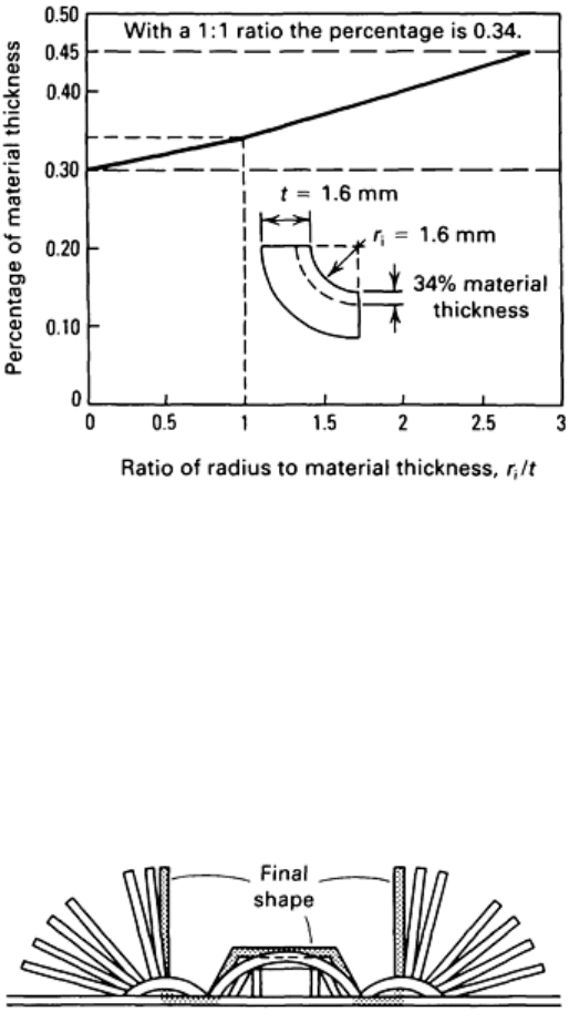
For a ratio greater than one or equal to one:
p = (r
A
- 1.0)0.6 + 0.34
(Eq 6)
where r
A
is the inside bend radius divided by the material thickness, r
i
/t. If p is calculated to be greater than 45%, the
value is 0.45.
Fig. 4 Nomograph used to determine perc
entage of material thickness required when calculating bend
allowance.
Flower Design. The development of the flower--the station-by-station overlay of progressive section contours, starting
with the flat strip width before forming and ending with the final desired section profile--is the first step in the design of
tooling for contour roll forming. The intermediate profiles between flat material and finished profile are graduated at a
rate that enables the section to be completed in the fewest number of stations of passes without compromising general roll
forming parameters. The flower graphically shows the number of passes required to roll form the given profile (Fig. 5).
Fig. 5 Development of a flower for design of roll forming rolls. See text for details.
The two prime considerations in designing the flower are: a smooth flow of material from first to last pass and maximum
control over fixed dimensions while roll forming. Other factors to be considered include forming position (a section is
usually formed in an upward position), vertical reference line with respect to the number and severity of bends, and drive
line (the optimal placement in the rolls for equal top and bottom surface speeds).
Roll Design Parameters. After the flower is completed to the satisfaction of the designer, rolls may be drawn around
each overlay. For small sections, the roll material should contact the section material as much as possible. It is possible,
however, to go too far and overdesign rolls, thereby creating too much roll contact, which can be detrimental. Each roll
pass must be examined not only by itself but as part of the total job to determine where to make contact with the section
material, where to exaggerate pressures or dimensions, where to clear out rolls so that material flows without restriction
from one pass to another, and how to accept the section material from the previous configuration.
Rolls are usually made progressively larger in diameter from one pass to the next to permit the surface speed of each
succeeding station to increase. The diameter increase is called step-up. The speed differential between passes creates a
tension in the section material and eliminates the possibility of an overfeed between passes. Overfeed is created by an
excessive amount of work being done in a single pass, which stretches the section material. Normal step-up is
approximately 0.8 mm ( in.) per pass on diameter, but it varies depending upon the gage of the section and the
particular amount of forming being done in those passes.
Rolls may be solid or split (segmented) depending on the complexity of the section. Simple rolls are usually of a one-
piece design, but as complexity of the workpiece increases, the use of split rolls should be considered. There are seldom
any marked disadvantages in using split rolls, and one or more of the following advantages can often be gained:
• Turning, grinding, or other machinin
g operations are usually easier to perform on the separate sections of split
rolls than on one-piece rolls having a complex contour
• Sections of split rolls are less susceptible to cracking in heat treatment than are single complex rolls
• Handling problems are simplified, particularly for large roll sections
•
Because sections of rolls subject to excessive wear or breakage can be replaced separately, split rolls can be more
economical than one-piece rolls
• Split rolls permit the use of different roll materials, as needed, for areas of high and low wear
•
Split rolls allow flexibility in making different widths of the same section by the use of spacers or additional roll
sections
• Split rolls allow for minor adjustments that cannot be made with one-piece rolls
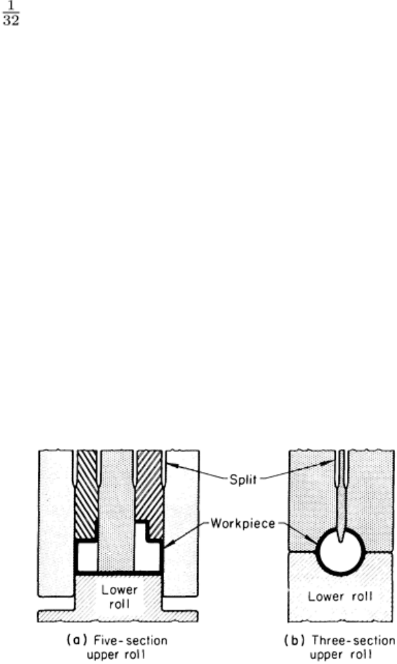
Figure 6 illustrates some of the above advantages of split rolls. In Fig. 6(a), the upper roll is composed of five separate
sections. In addition to being easier to manufacture, split rolls of this type can accommodate minor adjustments (by shims
or similar means) after the initial trial and before the first production run.
Fig. 6 Two types of split rolls use
d in contour roll forming. (a) Upper roll constructed in five sections allows for
minor adjustments. (b) Three-section upper roll allows replacement of center section.
Figure 6(b) shows an upper forming roll made up of three sections--a narrow center section flanked by two wider
sections. In use, the center section is subjected to a higher rate of wear than are the adjacent flanking sections. The center
section of this forming roll can be replaced without changing the flanking sections, or can be made from a more wear-
resistant metal.
Roll Materials. The materials that are most commonly used for contour rolls are:

• Low-carbon steel, turned and polished but not hardened
• Gray iron (such as class 30), turned and polished but not hardened
• Low-alloy tool steel (such as O1 or L6), hardened to 60 to 63 HRC and sometimes chromium plated
• High-carbon high-chromium tool steel (such as D2), hardened to 60 to 63 HRC and sometimes chromium plated
• Bronze (usually aluminum bronze)
The quantity of parts to be rolled is usually the major factor in choosing the most appropriate roll material, although other
factors, as noted below, also affect selection to some extent, and one or more of them may become definitive in particular
applications.
Short-Run Production. For rolling small quantities of a specific shape, or when repeat orders are not expected, rolls
made of either low-carbon steel or gray iron are commonly used. When the work metal is soft and corner radii are
generous, low-carbon steel or gray iron rolls can be used for medium- or high-production runs because rolls are easily
made from these materials and are not expensive.
Medium-Run Production. As the size of the production run increases, rolls made of hardened, ground, polished tool
steel, such as O1 or L6, are usually more economical and are widely used. Not only are these materials relatively
inexpensive, they machine more easily than more highly alloyed tool steels and they can be heat treated by simple
procedures. Rolls made of these steels can be plated with up to 25 m (1 mil) of chromium to reduce galling or scratching
of the work metal, or to extend tool life between grinds by decreasing roll wear or minimizing corrosion or pitting.
Long-Run Production. For long production runs (>5 million ft) or continuous high production, it is usually more
economical to make rolls from one of the high-carbon high-chromium tool steels, such as D2. These highly alloyed
grades cost nearly twice as much as O1, are more difficult to machine and grind, and require more complex heat
treatments, but because of their longer life between regrinds, are usually more economical for long runs.
Factors Other Than Quantity. Three other conditions, under any one of which rolls made of steel such as D2 are
often preferred (quantity becoming a secondary consideration), are: excessively hard work metal (low formability),
excessively sharp radii or other severe forming conditions, and work metal surfaces that are abrasive (such as unpickled
hot-rolled steel) and cause excessive roll wear. Rolls made of highly alloyed tool steel may also be plated with chromium
for the reasons mentioned in the section "Medium-Run Production" above.
Special Finish Requirements. In many applications, such as the rolling of light-gage stainless steel, aluminum
alloys, or coated stock, preservation of surface finish is of primary concern. With these work metals, softer rolls are used
to avoid damaging the work metal surface, even though there may be a substantial reduction in roll life.
As workpiece surface finish requirements become more rigorous, softer rolls are required. Rolls made of bronze are often
used. In some applications, the plating of hardened steel rolls is sufficient to prevent the marring of work metal surface
finish.
Contour Roll Forming
Tube and Pipe Rolling
Welded-seam pipe and tube are contour roll formed by three methods: edge forming, center forming, and true-radius
forming. Edge and center forming (Fig. 7a and b) require complete sets of rolls for each size of tube, because the stations
that precede welding have the final radii in the roll contours. In true-radius forming (Fig. 7c), the breakdown rolls can be
used for a range of sizes, which reduces tooling cost and setup time.