Warnick C.C. Hydropower engineering
Подождите немного. Документ загружается.

1
48
Water Passages
Chap.
8
of 9000 kW, a full-gate discharge of
1970
ft3/sec
(55.8
m3/sec), and arated net
head of 60 ft (1 8.3
m).
Indicate the approximate required space for accom-
modating the turbines.
8.3. Prepare a preliminary plan drawing for the required spiral case in Problem 8.2.
8.4. From a hydropower plant in your vicinity, obtain data to determine the
various controlling dimensions of the spiral case and draft tube similar to
those listed in Figs.
8.9
through 8.13 and check at least two dimension values
with the empirical equations presented for spiral case and draft tube size
determination.
8.5.
Prepare a neat line drawing for generalized dimensioning of draft tubes for
a
bulb turbine unit or tubular turbine unit and prepare a flow diagram of how
you would develop the empirical equations and diagrams similar to the work
of
deSiervo and deleva.
8.6.
A
very small hydropower site has a rated potential capacity of
250
kW and is
to have two penstocks.
If
the length of the penstock is 3700 ft
(1
128
rn)
and
the gross head is 405 ft (123.4
m),
select suitable penstocks assuming the
turbine efficiency will be 85%. Make all necessary assumptions to determine
a
suitable penstock.
SYNCHRONOUS GENERATORS
Converting water energy to electric energy at hydropower plants is possible through
the operation and functioning of electrical generators. The phenomenon of produc-
ing
an
electrical current
in
a conductor, discovered by Michael Faraday, involves
moving a copper coil through a stationary magnetic field or moving a magnet
through a copper coil. In the practical generator, an induced voltage is caused by
the magnetic field of a rotor sweeping by the coils of the stator. The rotor of an
electrical generator in the case of hydropower developments is driven by the rota-
tion of the turbine. Usually, the turbine and generator are directly connected on a
common shaft. Most generators used in hydropower developments are
alternating-
current (ac) synchronous generators. These require excitation current which is
usually provided by a small auxiliary generator that supplies direct current to create
the magnetic field of the rotor.
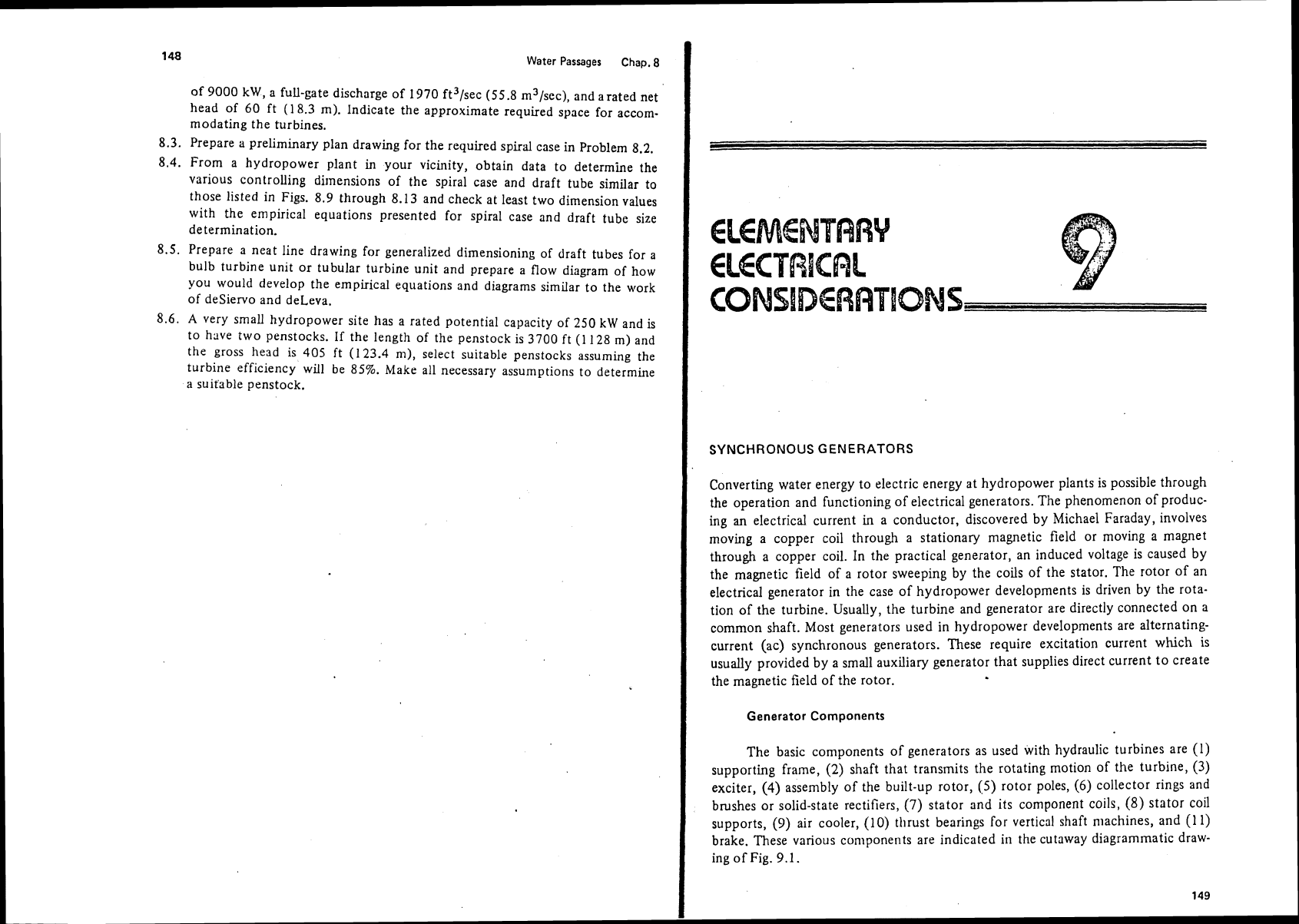
Generator Components
The basic components of generators as used with hydraulic turbines are (1)
supporting frame,
(2)
shaft that transmits the rotating motion of the turbine,
(3)
exciter,
(4)
assembly of the built-up rotor,
(5)
rotor poles,
(6)
collector rings and
brushes or solid-state rectifiers,
(7)
stator and
its
component
coils,
(8)
stator coil
supports,
(9)
air cooler, (10) tllrust bearings for vertical shaft machines, and (1 1)
brake. These various components are indicated in the cutaway diagrammatic draw-
ing of
Fig.
9.1.
Elementary Electrical Considerations Chap.
9
I
Synchronous Generators
I
Collector ring and brushes
;
Statw coil support
Bearing
I
Shaft
Figure
9.1
Cutaway diagrammatic drawing of synchronous electrical generator.
The stator contains the armature in conventio~ial ac generators and consists of
windings of coils pressed into slots in a
syrn~iietrical pattern. The core of the stator
is composed of laminated steel sheets to reduce power losses by hysteresis and eddy
currents.
The rotor contains the coils that make up the electromagnets or field winding.
The windings surround the individual poles that are mounted on a structure that
makes up a wheel attached to the rotary shaft. If the windings surround each pole
in a symmetrical fashion and are wound individually around a pole that extends out
from a cylindrical surface, they are termed
soliet~t-pole
fields.
The number of coils, the wire size and number of turns in a coil, and the
number of slots in a stator are design considerations by whjch size and capacity
of the generator are varied. Sonietimes a double layer of windings is pressed into
the slots. These windings
may be connected in series
01.
parallel to achieve the
desired voltage or current ratings. For actual
functio~ijng of the generator, it is then
necessary to have twice ttie
number of coiis per phase per pair of poles.
The
phase
refers to the manner in which tile electrical currentis taken from
the windings.
A
single-phase current is a situation or arrangement in which electric
current
1s taken from the generator with one armature winding and delivers electric
current to two wires.
A
two-phase generator has two annature windings generating
two single phases of current
90
electrical degrees apart in phase, and the output
electric current is connected to a four-wire system.
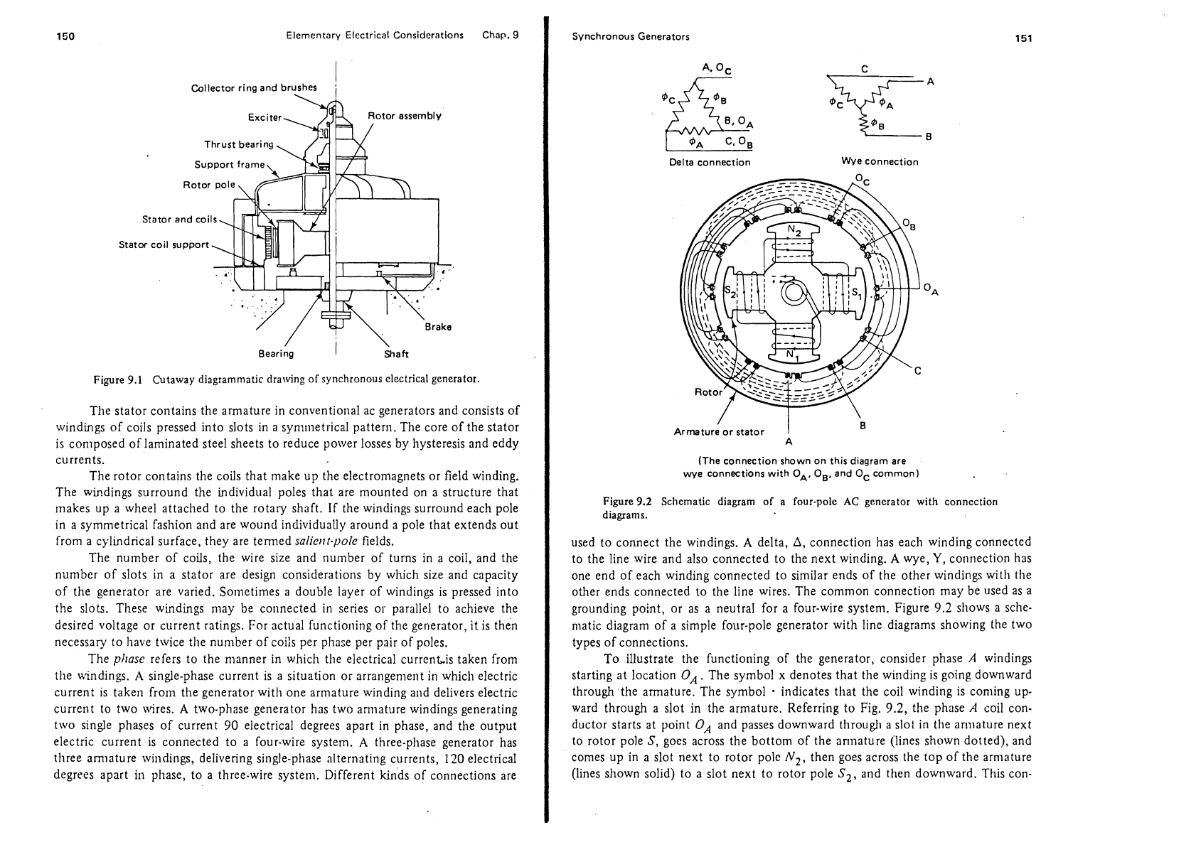
A
three-phase generator has
three
amiature wilidings, delivering single-phase alternating currents,
120
electrical
degrees apart
in
phase, to a three-wire system. Different kinds of connections are
Delta connection Wve connection
/
Armature or stator
A
(The connection shown on this diagram are
wye connections with
OA,
OB,
and
Oc
common)
i
Figure
9.2
Schematic diagram of a four-pole
AC
generator with connection
diagrams.
used to connect the windings.
A
delta,
A,
connection has each winding connected
to the line wire and also connected to the next winding.
A
wye,
Y,
connection has
one end of each winding connected to similar ends of the other windings with
the
other ends connected to the line wires. The common connection may be used as a
grounding point, or as a neutral for a four-wire system. Figure
9.2
shows a sche-
matic diagram of a simple four-pole generator with line diagrams showing the
two
types of connections.
To illustrate the functioning of the generator, consider phase
A
windings
starting at location
OA.
The symbol x denotes that the winding is going downward
through the armature. The symbol
indicates that the coil winding is coming up-
ward through a slot in the armature. Referring to Fig.
9.2,
the phase
A
coil con-
ductor starts at point
OA
and passes downward through a slot in the ar~nature next
to rotor pole
S,
goes across the bottom of the ani~ature (lines shown dotted), and
comes up in a slot next to rotor
pole
N2,
then goes across the top of the armature
(lines shown solid) to a slot next to rotor pole
Sf,
and then downward. This con-
152
Elementary Electrical Considerations Chap. 9
tinues until the coil winding ends up back at the next slot marked
OA.
The slot
spacing and number of windings are design variables for changing the output of the
generator. The
B
and
C
phases take a similar relative path.
The field winding
magnetic circuit and rotor consists of poles that are dupli-
cates of each other except that they are arranged alternately north and south
magnetically.
A
full cycle of alternating current is developed for each pair of
magnetic poles swept by the winding, that is, one cycle per two poles. The fixed
number of poles is provided in a full circle and must be an even-integer
number of
poles, because a north pole must exist for each south pole. The following funda-
mental formula must be met:
where
f
=
frequency,
Hz
(=
cycles/sec)
.
Np
=
number of poles
II
=
speed, rpm
or,
irrotative speed,
w,
is in radians per second,
There are only a limited number of frequencies used for ac power frequencies. The
usual ones are
25, 50, 60,
and
400
Hz. The most common frequency used with
hydropower generators in North America is
60
Hz.
Power
Factor
In most operations of generators it is important to recognize the concept of
power factor.
In
usual generator circuits there is inductive reactance and the load
current lags or leads the voltage by an angle,
8,
measured as a part of the
360'
electrical cycle. The value of cos
0
is the power factor,
PF.
To illustrate this, con-
sider the
simple ac diagram in Fig.
9.3.
To understand the effect of power factor on synchronous ac generators, it is
necessary to consider three conditions:
(1)
unity power factor load,
(2)
lagging
power factor load, and
(3)
leading power factor load. Additional knowledge of the
characteristics of ac generators is needed to explain fully the importance of these
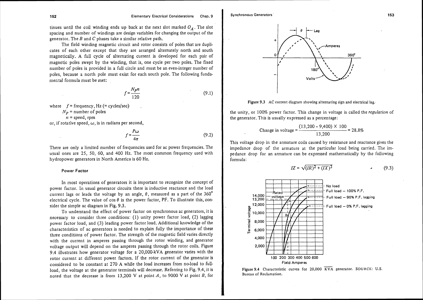
three conditions of power factor. The strength of the magnetic field varies directly
with the current in amperes passing through the rotor winding, and generator
voltage output will depend on the amperes passing through the rotor coils. Figure
9.4
illustrates how generator voltage for a
20,000-kVA
generator varies with the
rotor current at different power factors. If the rotor current of the generator is
considered to be constant at
270
A
while the load increases from no-load to full-
load, the voltage at the generator terminals will decrease. Referring to Fig.
9.4,
it is
noted
that
the decrease
is
from
13,200
V
at point
A,
to
9000 V
at point
B,
for
Synchronous Generators
Figure
9.3
AC
current diagram showing alternating
sign
and electrical
lag.
the unity, or
100%
power factor. This change in voltage is called the
regularior~
of
the generator. This is usually expressed as a percentage:
(1
3,200
-
9,400)
X
100
Change in voltage
=
=
28.8%
13,200
This voltage drop in the armature coils caused by resistance and reactance gives the
impedance drop
of the armature at
the particular load being carried.
Tile
im-
pedance drop for an armature can be expressed mathematically by the following
formula:
IZ
=
~(IR)~
+
(1x1~
*
(9.3)
No load
Full load
-
100% P.F.
Full load
-
90% P.F. lagging
Full load
-
0% P.F. lagging
Field Amperes
Figure
9.4
Cl~aractcristic curves for 20,000
FA
generator.
SOURCE:
U.S.
Bureau of Reclamation.
154
Elementary Electrical Considerations Chap.
9
where
IZ
=
impedance drop,
V
I
=
armature current,
A
Z
=
armature impedance, S2
R
=
armature effective resistance,
X
=
armature reactance,.n.
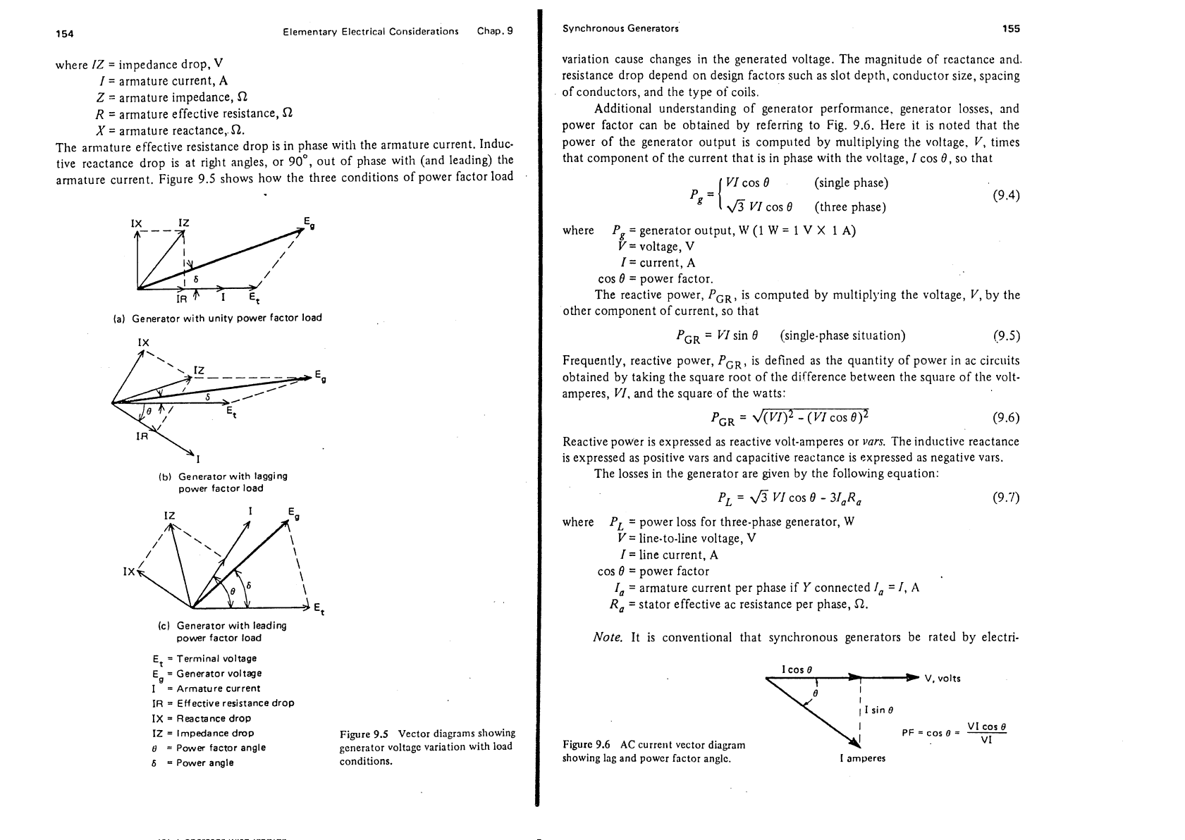
The armature effective resistance drop is in phase with the armature current. Induc-
tive
rcactance drop is at riglit angles, or 90°, out of phase with (and leading) the
armature current. Figure 9.5 shows how the three conditions of power factor load
la) Generator with unity power factor load
(b)
Generator with lagging
power factor load
Icl Generator with leadins
power factor load
Et
=
Terminal voltage
Eg
=
Generator voltage
I
=
Armature current
IR
=
Effective resistance drop
IX
=
Reactance drop
IZ
=
Impedance drop Figure
9.5
Vector diagrams showing
8
=
Power factor angle
generator
voltagc variation with load
6
=
Power angle conditions.
I
Synchronous Generators
155
variation cause changes in the generated voltage. The magnitude of reactance and.
resistance drop depend on design factors such as slot depth, conductor size, spacing
of conductors, and the type of coils.
Additional understanding of generator performance. generator losses, and
power factor can be obtained by referring to Fig. 9.6. Here it is noted that the
power of the generator output is computed by multiplying the voltage. V, times
that component of the current that is in phase with the voltage,
I
cos
8,
so that
VI
cos
8
(single phase)
6
VI
cos
8
(three phase)
where
Pg
=
generator output,
H1
(1
W
=
1
V
X
1
A)
V
=
voltage,
V
I
=
current,
A
cos
8
=
power factor.
The reactive power,
PGR,
is computed by multipl>*ing the voltage, V, by the
other component of current, so that
I
PGR
=
VI
sin
0
(single-phase situation) (9.5)
I
Frequently, reactive power,
PGR,
is defined as the quantity of power in ac circuits
obtained by taking the square root of the difference between the
square of the volt-
amperes, VI, and the square of
the
watts:
i
P,,
=
-
(VI cos
0)2
(9.6)
I
Reactive power is expressed as reactive volt-amperes or
vars.
The inductive reactance
is expressed as positive vars and capacitive reactance is expressed as negative vars.
The losses in the generator are given by the following equation:
PL
=
fi
VI
cos
0
-
31,Ra
(9.7)
where
PL
=
power loss for three-phase generator,
W
V=
line-to-line voltage,
V
I
=
line current,
A
cos
8
=
power factor
I,
=
armature current per phase if
Y
connected
1, =I,
A
R,
=
stator effective ac resistance per phase,
R.
I
Note.
It is conventional that synchronous generators be rated by electri-
1
cos
e
V, volts
I
1
sin
6
7.
PF
=
cos
e
=
-
VI
cos
e
Figure
9.6
AC
current
vector
diagram
VI
showing lag and
powcr factor anglc.
I
amperes
I
Elementary Electrical Considerations Chap.
9
Synchronous Generators
157
120
,
100
,- ,-
3
0
80
-
.-
1
60
VI
0)
40
friction losses
20
Load in
KVA
-
80% P.F.
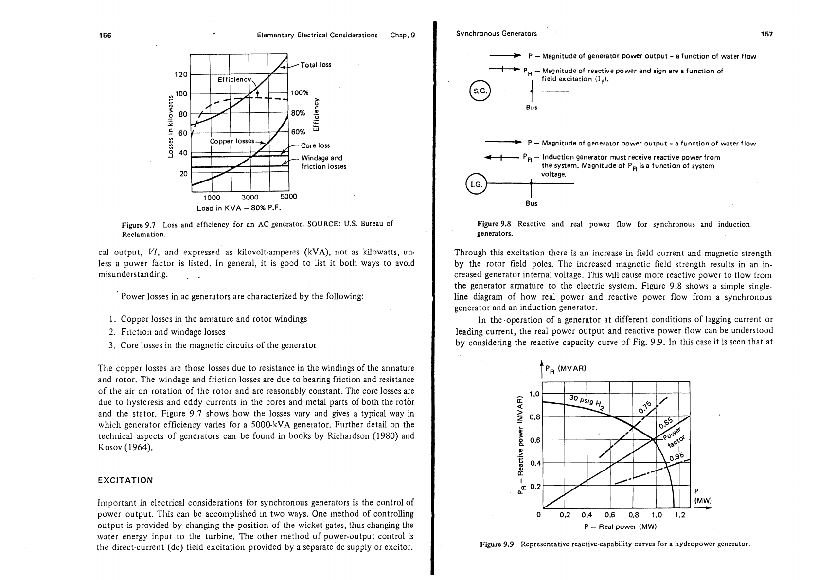
Figure
9.7
Loss and efficiency for an
AC
generator.
SOURCE:
U.S.
Bureau of
Reclamation.
cal output,
VI,
and expressed as kilovolt-amperes
(kVA),
not as kilowatts, un-
less a power factor is listed. In general, it is good to list it both ways to avoid
misunderstanding.
.
.
Power losses in ac generators are characterized by the following:
1.
Copper losses
in
the armature and rotor windings
2.
Frictior~ and windage losses
3.
Core losses in the magnetic circuits of the generator
The copper losses are those losses due to resistance in
the windings of the armature
and rotor. The windage and friction losses are due to bearing friction and resistance
of the air on rotation of the rotor and are reasonably constant. The core losses are
due
to hysteresis and eddy currents in the cores and metal parts of both the rotor
and rhe stator. Figure
9.7
shows how the losses vary and gives a typical way in
which generator efficiency varies for a
5000-kVA generator. Further detail on the
technical aspects of generators can be found in books by Richardson
(1980)
and
Kosov
(1964).
EXCITATION
Ilnportant in electrical considerations for synchronous generators is the control of
power output. This can be accomplished in two ways. One
inethod of controlling
output is provided by changing the position of the wicket gates,
thus changing the
wster energy input to the turbine. The other method of power-output control is
the direct-current (dc) field excitation provided by a separate dc supply or
excitor.
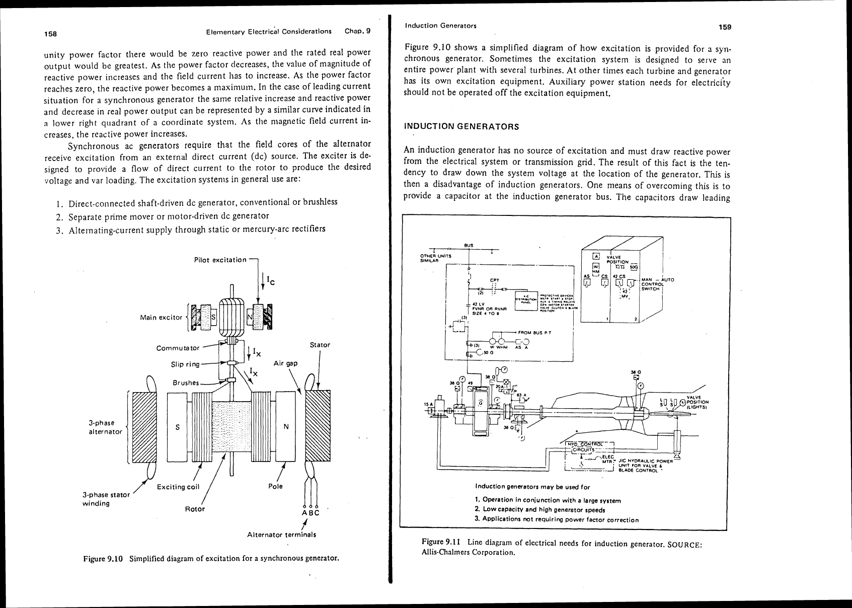
-
P
-
Magnitude of generator power output
-
a
function of water flow
I
PR
-
Magnitude of reactive power and sign are a function of
field excitation
(I,).
@+
Bus
-
P
-
Magnitude of generator power output
-
a function of water flow
4-
PR
-
Induction generator must receive reactive power from
the system. Magnitude of
PR is a function
of
system
voltage.
Bus
Figure 9.8 Reactive and real power flow for synchronous and induction
generators.
Through this excitation there is an increase in field current and magnetic strength
by the rotor field poles. The increased magnetic field strength results in an in-
creased generator internal voltage. This will cause more reactive power to flow from
the generator armature to the electric system. Figure
9.8
shows a simple singe-
line diagram of how real power and reactive power flow from
a
synchronous
generator and an induction generator.
In the operation of a generator at different conditions of lagging current or
leading current,
the real power output and reactive power flow can be understood
by considering the reactive capacity curve of Fig.
9.9.
In this case it is seen that at
P
-
Real power (MW)
I
Figure 9.9 Representative reactive-capability curves for a hydropower generator.
158
Elementary ~lectricil Considerations Chap.
9
unity power factor there would be zero reactive power and the rated real power
output would be greatest. As the power factor decreases, the value of magnitude of
reactive power increases and the field current has to increase. As the power factor
reaches zero, the reactive power becomes a
maximum. In the case of leading current
situation for a synchronous generator the
same relative increase and reactive power
and decrease in real power output can be represented by a similar curve indicated in
n
lower right quadrant of a coordinate system. As the magnetic field current in-
creases, the reactive power increases.
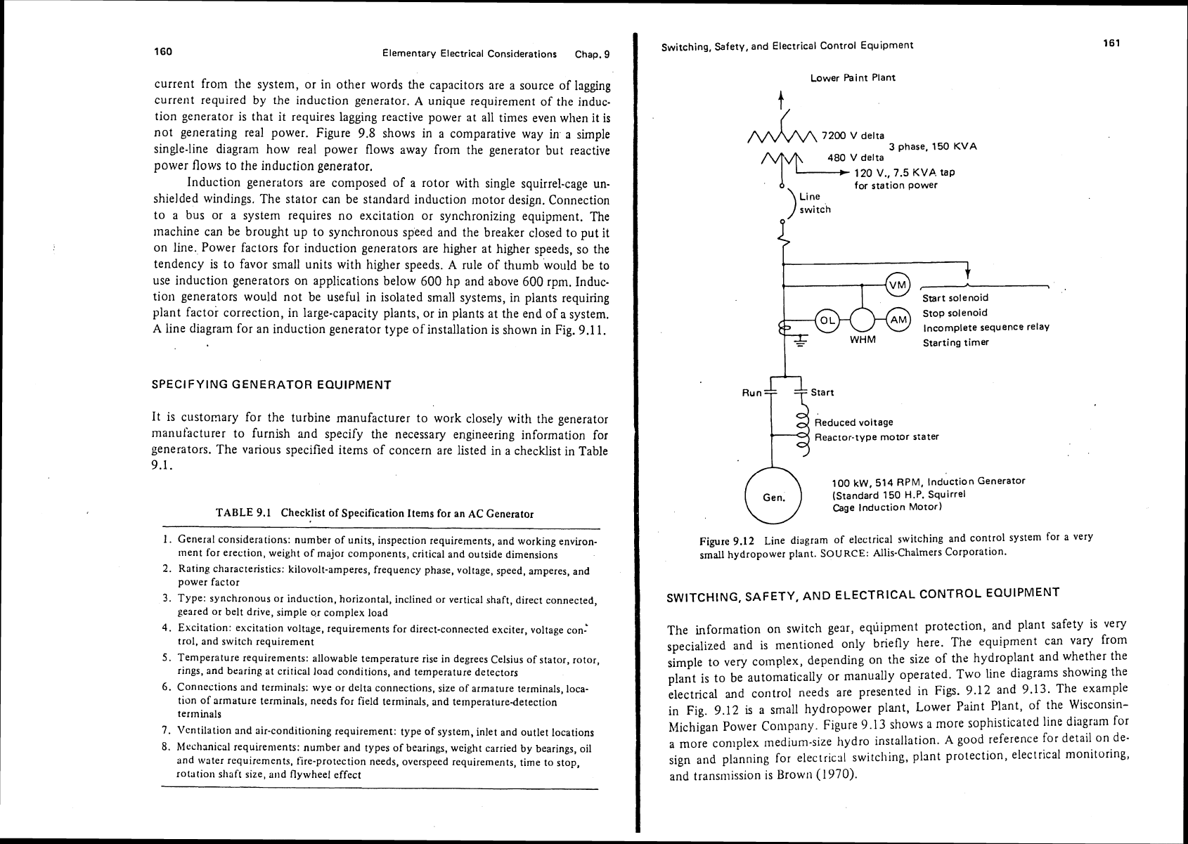
Synchronous ac generators require that the field cores of the alternator
receive excitation from an external direct current (dc) source. The exciter is de-
signed to provide a flow of direct current to the rotor to produce the desired
voltage and var loading. The excitation systems in general use are:
I.
Direct.co11nected shaft-driven dc generator, conventional or brushless
2.
Separate prime mover or motor-driven dc generator
3.
Alternating-current supply through static or mercury-arc rectifiers
Pilot excitation
1
Ma~n excitor
Commutator
Stator
/
Exciting coil
/
Pole
3-phase stator
winding
/
Rotor
ddd
ABC
Alternator terminals
Fiyre
9.10
Sinlplified diag~am of excitation ior a synchronous generator.
Induction Generators
159
Figure
9.10
shows a simplified diagram of how excitation is provided for
a
syn-
chronous generator. Sometimes the excitation system is designed to serve an
entire power plant with several turbines. At other times each turbine and generator
has
its own excitation equipment. Auxiliary power station needs for electrici'ty
should not be operated off the excitation equipment.
INDUCTION GENERATORS
An induction generator has no source of excitation and must draw reactive power
from the electrical system or transmission grid. The result of this fact is the ten-
dency to draw down the system voltage at the location of the generator. This is
then a disadvantage of induction generators. One means of overcoming this is to
provide a capacitor at the induction generator bus. The capacitors draw leading
42
LV
FVND
01
DVNR
w.LvI
CLYIC-
I
.L.M
I
1
7
FROM
8US
P
T
1
lnduction generators may be used for
1.
Operation in conjunction with a large system
2.
Low capacity and high generator speeds
3.
Applications not requiring power factor correction
J
Figure
9.11
Line diagram of electrical needs
for
induction generator. SOURCE:
Allis-Chalmers Corporation.
160
Elementary Electrical Considerations Chap.
9
current from the system, or in other words the capacitors are a source of lagging
current required by the induction generator.
A
unique requirement of the induc-
tion generator is that it requires lagging reactive power at all
times even when it is
not generating real power. Figure 9.8 shows in a comparative way in
a
simple
single-line diagram how real power flows away from the generator but reactive
power flows to the induction generator.
Induction generators are composed of a rotor with single squirrel-cage
un-
shielded windings. The stator can be standard induction motor design. Connection
to a bus or a system requires no excitation or synchronizing equipment. The
machine can be brought up to synchronous speed and the breaker closed to put
it
on line. Power factors for induction generators are higher at higher speeds, so the
tendency is to favor small units with higher speeds.
A
rule of thumb would be to
use induction generators on applications below
600
hp and above
600
rpm. Induc-
tion generators would not be useful in isolated small systems, in plants requiring
plant factor correction, in large-capacity plants, or in plants at the end of a system.
A
line diagram for an induction generator type of installation is shown in Fig. 9.1 1.
SPECIFYING GENERATOR EQUIPMENT
It is customary for the turbine manufacturer to work closely with the generator
manufacturer to furnish and specify the necessary engineering information for
generators. The various specified items of concern are listed in a checklist in Table
9.1.
TABLE 9.1 Checklist of Specification Items for an AC Generator
1.
General considerations: number of units, inspection requirements, and working environ-
ment for erection, weight of major components, critical and outside dimensions
2. Rating characteristics: kilovolt-amperes, frequency phase, voltage, speed, amperes, and
power factor
3.
Type: synchronous or induction, horizontal, inclined or vertical shaft, direct connected,
geared or belt drive, simple
gr complex load
4.
Excitation: excitation voltage, requirements for direct-connected exciter, voltage con:
trol, and switch requirement
5.
Temperature requirements: allowable temperature rise in degrees Celsius of stator, rotor,
rings, and bearing at critical load conditions, and temperature detectors
6.
Connections and terminals: wye or delta connections, size of armature terminals, loca-
tion of armature terminals, needs for field terminals, and temperature-detection
terminals
7.
Ventilation
and air-conditioning requirement: type of system, inlet and outlet locations
8.
hfechanical requirements: number and types of bearings, weight carried by bearings, oil
and
water requirements, fire-protection needs, overspeed requirements, time to stop,
rotation sliaff size, and flywheel effect
Switching, Safety, and Electrical Control Equipment
Lower Paint Plant
4-
7200
V
delta
3
phase. 150
KVA
480
V
delta
1
120
V.,
7.5
KVP.
tap
for station power
\
Line
)
switch
?
w
Start solenoid
stop solenoid
Incomplete sequence relay
Starting timer
Run
start
.#'
Reduced voltage
Reactor-type motor stater
100
kW,
514 RPM, Induction Generator
(Standard 150
H.P.
Squirrel
Cage Induction Motor)
Figure 9.12 Line diagram of electrical switching and control system for a very
small hydropower plant.
SOURCE:
Allis-Chalmers Corporation.
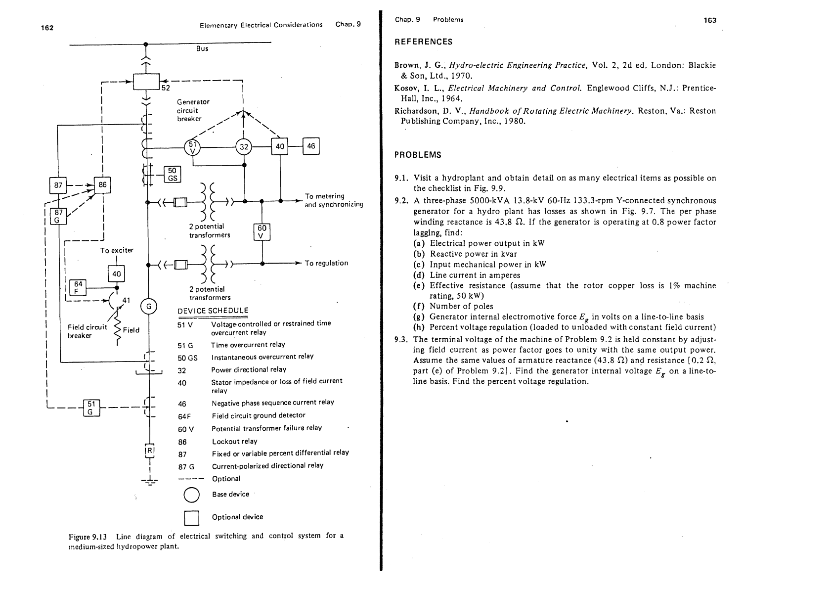
SWITCHING, SAFETY, AND ELECTRICAL CONTROL EQUIPMENT
The information on switch gear, equipment protection, and plant safety is very
specialized and is mentioned only briefly here. The equipment can vary from
simple to very complex, depending on the size of the hydroplant and whether the
plant is to be automatically or manually operated. Two line
diagrams showing the
electrical and control needs are presented in Figs.
9.12
and 9.13. The example
in Fig.
9.12
is
a small hydropower plant, Lower Paint Plant, of the Wisconsin-
hlichigan Power Company. Figure 9.13 shows a more sophisticated line diagram for
a
more conlplex medium-size hydro installation.
A
good reference for detail on de-
sign and planning for electrical switching, plant
protection,
electrical monitoring,
and transmission
is Brown (1970).
162
Elementary Electrical Considerations Chap.
9
-
Bus
~-+l$k
I
----+-
l
I
I
Generator
1
and synchronizing
2
potential
transformers
DEVICE SCHEDULE
51 V
Voltage controlled or restrained time
overcurrent relay
1
I
I
I
51
G
Time overcurrent relay
50
GS
Instantaneous overcurrent relay
32
Power directional relay
1
40 Stator impedance or loss of field current
I
relay
Negative phase sequence current relay
-
64F Field circuit ground detector
1
60
V
Potential transformer failure relay
A
86
~ockout relay
IRI
87
Fixed or variable percent differential relay
'
I
87
G
Current-polarizd directional relay
-1-
----
-
-
-
Optional
0
Basedevice
Optional dwice
Figure 9.13
Line
diagram of electrical
switching
and control system
for
a
medium-sized hydropower plant.
Chap.
9
Prob!ems
REFERENCES
Brown,
J.
G.;
Hydro-electric Engineering Practice,
Vol. 2, 2d ed. London: Blackie
&
Son, Ltd., 1970.
Kosov,
I.
L.,
Electricui Machinery
and
Control.
Englewood Cliffs,
N.J.:
Prentice-
Hall, Inc., 1964.
Richardson,
D.
V.,
Handbook of Rotating Electric Machinery.
Reston, Va.: Reston
Publishing Company, Inc., 1980.
PROBLEMS
9.1. Visit a hydroplant and obtain detail on as many electrical items as possible on
the checklist in Fig. 9.9.
9.2.
A three-phase 5000-kVA 13.8-kV 60-Hz 133.3-rpm Y-connected synchronous
generator for a hydro plant has losses as shown in Fig. 9.7. The per phase
winding reactance is 43.8
52.
If the generator is operating at 0.8 power factor
lagging, find:
(a) Electrical power output in
kW
(b)
Reactive power in kvar
(c)
Input mechanical power
in
kW
(d)
Line current in amperes
(e)
Effective resistance (assume that the rotor copper loss is 1% machine
rating, 50 kW)
(f)
Number of poles
(g)
Generator internal electromotive force
ER
in volts on a line-to-line basis
(h) Percent voltage regulation (loaded to unloaded with constant field current)
9.3.
The terminal voltage of the machine of Problem 9.2 1s held constant by adjust-
ing field current as power factor goes to unity with the same output power.
Assume the same values of armature reactance (43.8
R)
and resistance (0.2
R,
part (e) of Problem 9.21. Find the generator internal voltage
Eg
on a line-to-
line basis. Find the percent voltage regulation.
RND
SPEED
REGULATION,
-
Sudden shutdowns of hydroelectric plants or changes in water flow through hy-
draulic turbines may cause problems ranging from rupture of penstocks due to
water
hammer to runner speed changes that cause the line current of the generators
to vary from the desired frequency. Regulating the water flow and coping with
slrJ,ic~i
closurc
ill'
gates
31id
s'alsqes require special equipment such as governors,
przsiure relief valves,
an11
suge tanks. Solving the problems of pressure control and
speed
regulation requires an understandi~lg of the basic theory of water hammer.
WATER HAMMER THEORY
AND
ANALYSIS
Water hammer is a phenomenon of pressure change
in
closed pipes caused when
flowing water in a pipeline is decelerated or accelerated by closing or opening a
valve or changing the velocity of the water rapidly in some other manner. The phe-
nomenon is accompanied by a series of positive and negative pressure waves
which
travel back and forth in the pipe system until they are damped out by friction. The
various
con~ponents of a hydropower installation must be capable of withstanding
these changes.
When a valve in a pipe or penstock carrying water is closed, the pressure head
imnlediately upstream of the valve is increased,
and
a pulse of high pressure is
propagated upstream to the nearest open water surface. On the downstream side of
the valve a lowered pressure moves in a downstream direction to the nearest open
water surface. If
the valve closure is rapid enough, a decrease in pressure may be
sufficient to cause a vapor pocket to form on the downstream side of the valve.
Water Hammer Theory and Analysis
165
When that vapor pocket collapses a high-pressure wave moves downstream.
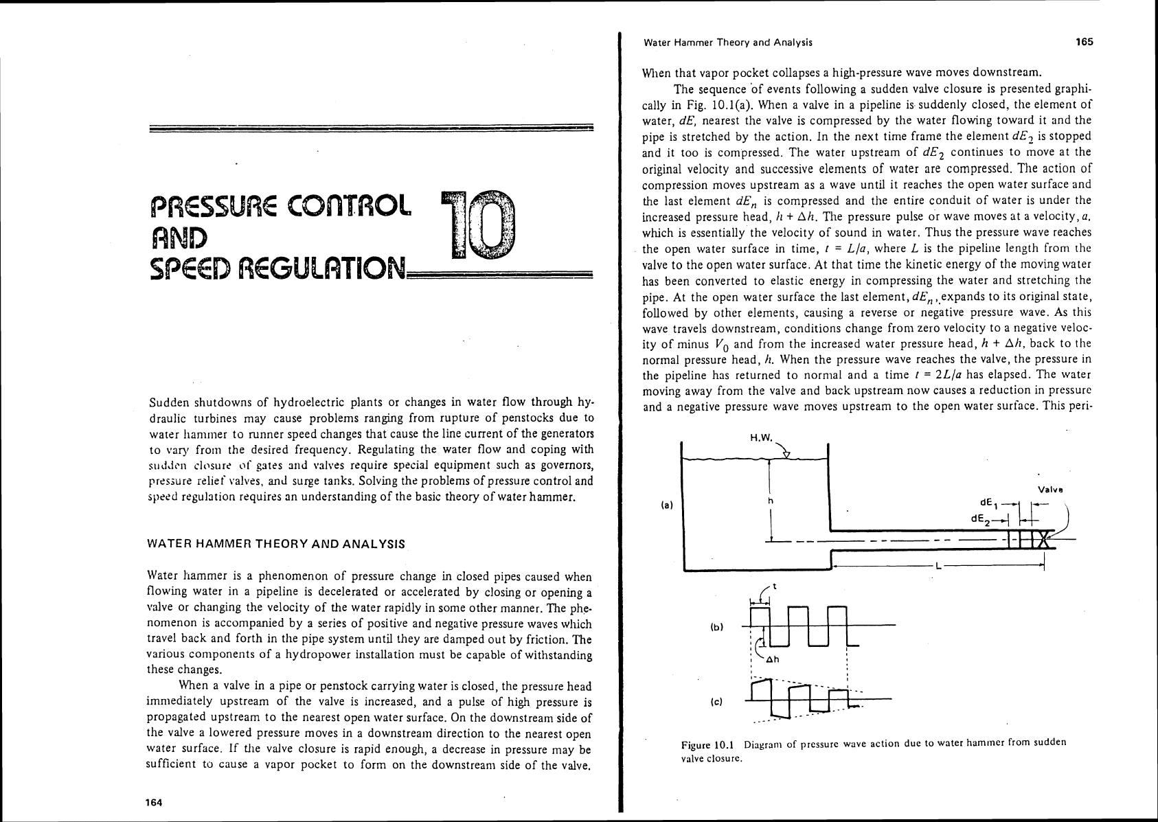
The sequence 'of events following a sudden valve closure is presented
graplli-
cally in Fig. IO.l(a). When a valve in a pipeline is suddenly closed, the element of
water,
dE,
nearest the valve is compressed by the water flowing toward it and the
pipe is stretched
by the action. In the next time frame the element
dE7
is stopped
and it too is compressed. The water upstream of
dE2
continues to move at the
original velocity and successive elements of water are compressed.
The
action of
compression moves upstream as a wave until it reaches the open water surface and
the last element
dE,
is compressed and the entire conduit of water is under the
increased pressure head,
k
t
Ah.
The pressure pulse or wave moves at a velocity,
Q.
which is essentially the velocity of sound in water. Thus the pressure wave reaches
the open water surface in time,
t
=
Lla,
where
L
is the pipeline length from the
valve to the open water surface. At that time the kinetic energy of the moving water
has been converted to elastic energy in compressing the water and stretching the
pipe. At the open water surface the last element,
dE,
,,expands to its original state,
followed by other elements, causing a reverse or negative pressure wave. As this
wave travels downstream, conditions change
from zero velocity to a negative veloc-
ity of minus
Vo
and from the increased water pressure head,
h
+
Ah,
back to the
normal pressure head,
h.
When the pressure wave reaches the valve, the pressure In
the pipeline has returned to normal and a time
t
=
2Lla
has elapsed. The water
moving away from the valve and back upstream now causes a reduction in pressure
and a negative pressure wave moves upstream to the open water surface. This
peri-
H.W.
Valve
Figure
10.1
Diagram of pressure wave action due to water hammer from sudden
valve closure.
1
G6
Pressure Control and
Speed
Regulation Chap.
10
odic fluctuation is shown schematically in Fig. lO.l(b) as if the water did not have
friction acting. In reality, friction does act
within the water and
at
the boundaries
so that the pulses of pressure change have a decreasing
aniplitude as shown
in
Fig. lO.l(e).
Pressure Wave Velocity
Engineering analysis of water llamnler necessitates use of the term,
a,
the
velocity of the pressure wave. According to
Parmakian (1955), the velocity of the
pressure wave in a pipe is given
by
the following formula:
where
a
=
velocity of the pressure wave, ft/sec
y
=
specific weight of water, 1b/ft3
g
=
acceleration of gravity, ft/sec2
K
=volume modulus of water
=
43.2
X
lo6 lb/ft2
d
=
diameter of pipe, in.
e
=
thickness of pipe, in.
E
=
Young's modulus of elasticity, 1b/ft2
for steel
=
4.32
X
lo9 1b/ft2
for cast iron
=
2.30
X
lo9 1b/ft2
for transite
=
0.49
X
lo9 1b/ft2
C1
=
factor for anchorage and support of pipe
C1
=
0.95 for pipe anchored at upper end and without expansion joints
C1
=
0.91 for pipe anchored against longitudinal movzment
Cl
=
0.85 for pipe with expansion joints.
Parmakian
(1955) gives details on how to determine a value for the pressure wave
velocity,
a,
for composite pipes and reinforced concrete pipes. If
a
penstock or pipe
is
embedded
in
Inass concrete, it is customary to consider the velocity of the pres-
sure wave,
a,
equal to a value of less than
4660
ft/sec, the velocity of sound in
water. When
a
steel penstock is embedded
in
concrete, it is embedded with a corn-
pressible membrane, called a
nlastic
blanket,
around it or it is embedded under full
hydrostatic pressure plus the expected illcrease in pressure caused by water hammer.
Thus the steel penstock will expand under transient pressure to prevent internally
loading the
silrrounding concrete under tension stresses.
Two approaches to the theory of water
hammer have evolved: the rigid water
column theory
and the elastic water colunln theory.
Rigid Water Column Theory
Early investigators showed that for pipes that do not stretch, water that is
incompressible, the pipeline full
at all times, hydraulic losses negligible, velocity
uniform in the direction of tile pipe axis, a uniform pressure over the transverse
Water Hammer Theory and Analysis
167
cross section of the pipe, and no fluctuation in the open headwater level, the fol-
lowing equation applies for uniform rates of closure of the valve or gate:
where
(h,),,
=
maximum rise in pressure head at gate due to uniform closure, ft
hO
=
initial steady pressure head at gate, ft.
LV'
2
K1
=(rn)
where
L
=
length of pipe, ft
V'
=
difference between initial and final steady velocity, ftlsec
g
=
acceleration of gravity, ft/sec2
T=
time for gate closure or opening, sec.
The maximum drop in head at a gate or valve due to uniforrn gate opening is given
by
the equation
where
(h:),,
=
maximum drop in head at gate due to uniform gate opening, ft.
This approach is limited to slow-gate movement and according to Parmakian
(1955) should be used only when
T
is greater than L11000. For rapid gate move-
ments, the elastic water column theory and analysis should be used.
Elastic Water
Column
Theory
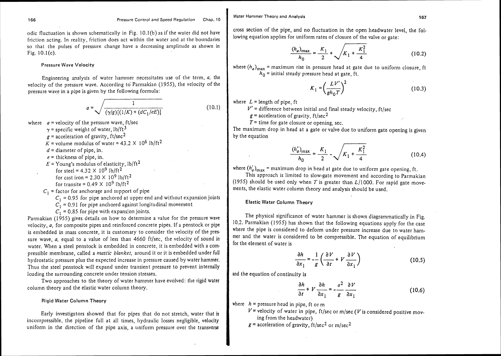
The physical significance of water hammer is shown diagrammatically in Fig.
10.2.
Parmakian
(1
955) has shown that the following equations apply for the case
where the pipe is considered to deform under pressure increase due to water ham-
mer and the water is considered to be compressible. The equation of equilibrium
for the element of water is
and the equation of continuity is
where h
=
pressure head in pipe, ft or
m
V=
velocity of water in pipe, ftlsec or mlsec
(V
is considered positive mov-
ing from the
headwatcr)
g
=
acceleration of gravity, ft/sec2 or m/sec2