Warnick C.C. Hydropower engineering
Подождите немного. Документ загружается.

Powerhouses and
Facilities
Chap.
11
Switchyard
Brahmaputra Barrage
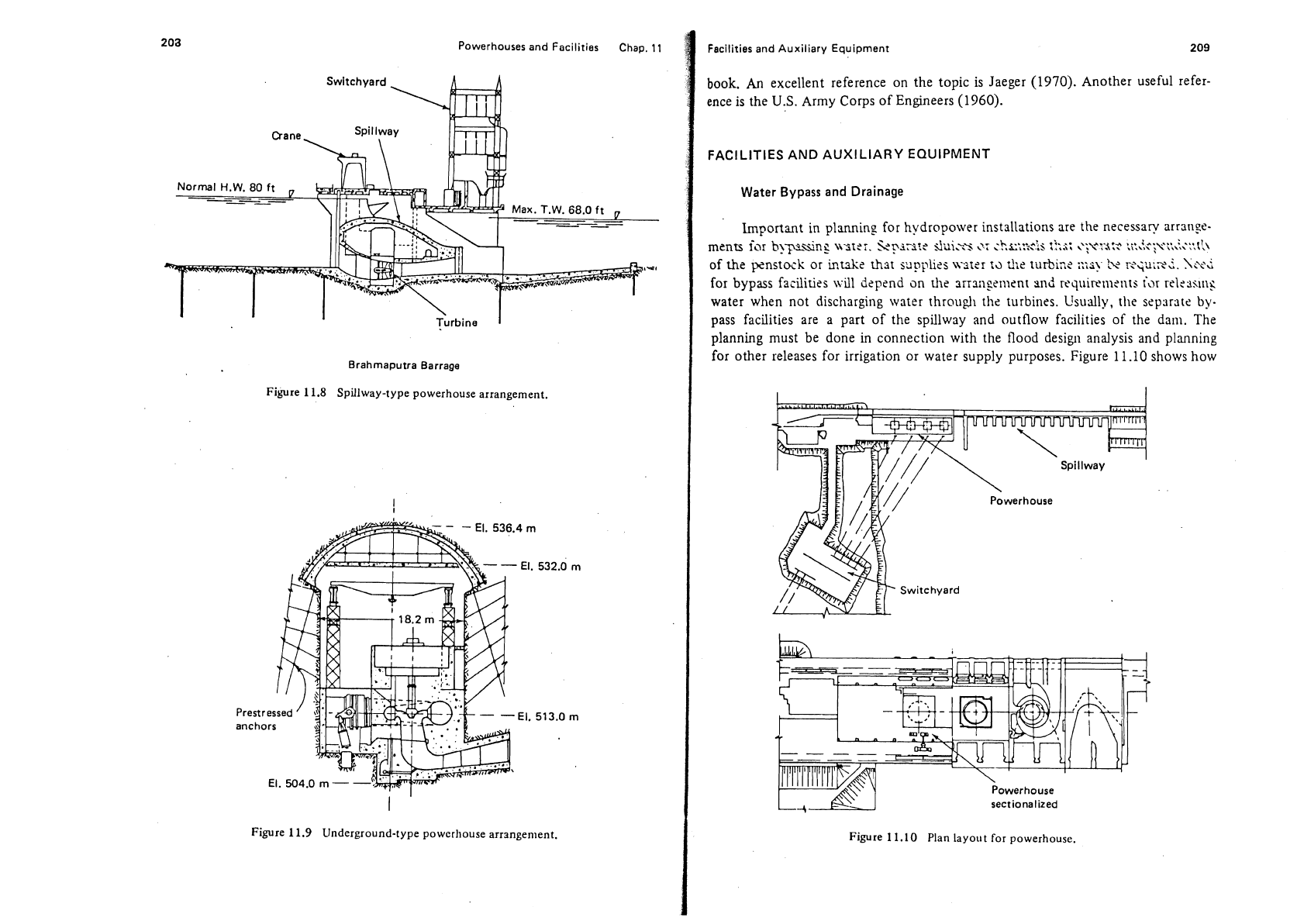
Figure
11.8
Spillway-type powerhouse arrangement.
Figure
11.9
Underground-type
powerhouse
arrangement.
Facilities and Auxiliary Equipment
209
book.
An
excellent reference on the topic
is
Jaeger (1970). Another useful refer-
ence
is
the
U.S.
Army Corps of Engineers (1960).
FACILITIES AND AUXILIARY EQUIPMENT
Water
Bypass
and Drainage
hportant in
planning
for hydropower installations are the necessary arrange-
,.:..,>
I?,$:
,yeYs:?
:i:2.?~~?,:,::+\t',\
mcnrs
iar
b>-py-sing
\\grei.
St,-r\iri?t
dui:cs
',:
;h~..*!-
'
of the penstock or kuke rhar applies \A-srer
r;l
d;c
turbine
I:;;;?.
tv
r>;u;xt.
?;cvi
for bypass facilities
\\.ill
ckpend
on
die
zirrsi~gement wd requirenlents
i\>r
relesslilt:
water when not discharging water through tllc turbines. Usually, the sepsrstc
by-
pass facilities are a part of the spillway and outflow facilities of the dam. The
planning must be done in connection with the flood design analysis and planning
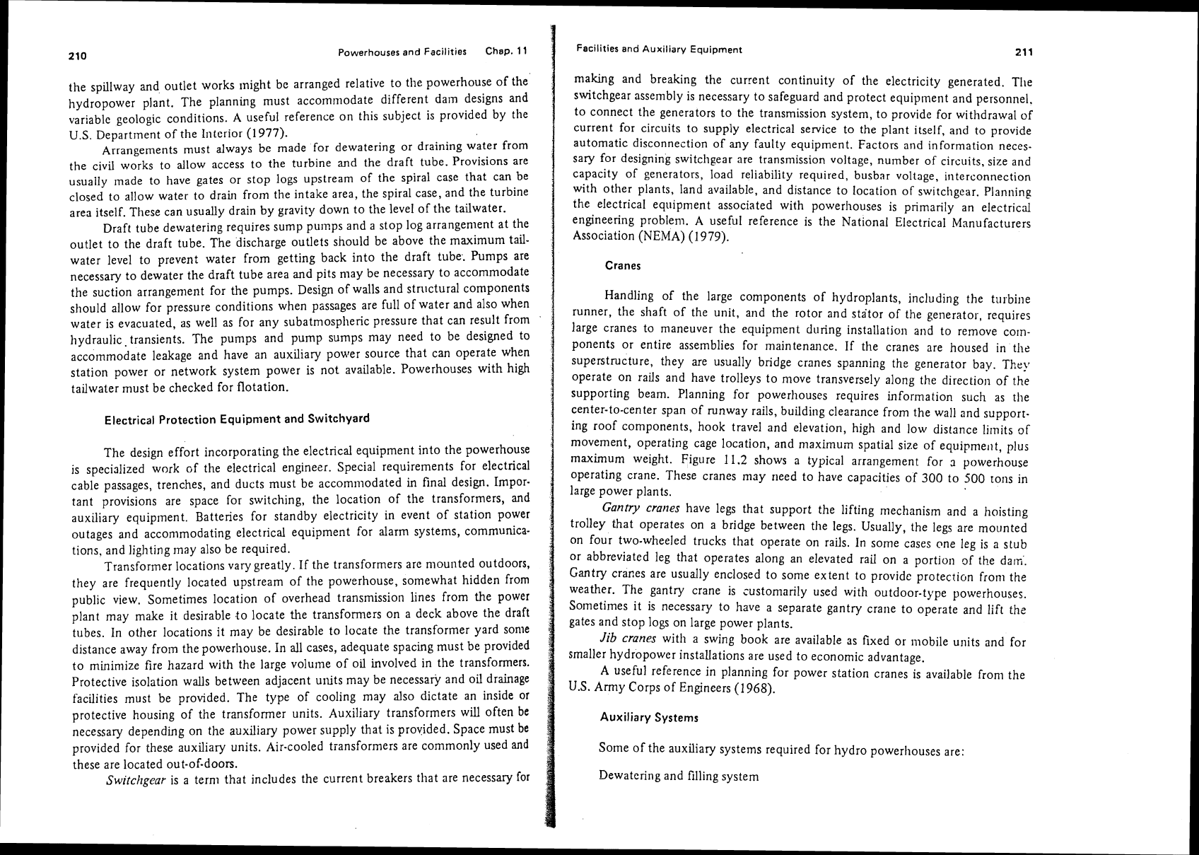
for other releases for irrigation or water supply purposes. Figure 11.10 shows how
Powerhouse
sectionalized
Figure
11.10
Plan layout for powerhouse.
210
Powerhouses and Facilities Chap.
11
the spillway and outlet works might be arranged relative to the powerhouse of the
hydropower plant. The
plannulg must accomnlodate different dam designs and
var~able geologic conditions. A useful reference on this subject is provided by the
U.S. Department of the Interior
(1977).
Arrangements must always be made for dewatering or draining water from
the civil works to allow access to the turbine and the draft tube. Provisions are
usually
made to have gates or stop logs upstream of the spiral case that can be
closed to allow water to
drain from the intake area, the spiral case, and the turbine
area itself. These can usually drain by gravity down to the level of the tailwater.
Draft tube dewatering requires sump
pu~llps and a stop log arrangenlent at the
outlet to the draft tube. The discharge outlets should be above the maximum
tail-
water level to prevent water from getting back into the draft tube. Pumps are
necessary to dewater the draft tube area and pits may be necessary to accommodate
the suction
arrangement for the pumps. Design of walls and stn~ctural components
should allow for pressure conditions when passages are full of water and also when
water is evacuated, as well as for any
subatmospl~eric pressure that can result from
hydraulic. transients. The pumps and pump sumps may need to be designed to
accommodate leakage and have an auxiliary power source that can operate when
station power or network system power is not available. Powerhouses with high
tailwater must be checked for flotation.
Electrical Protection Equipment
and
Switchyard
The design effort incorporating the electrical equipment into the powerhouse
is specialized work
cf the electrical engineer. Special requirements for electrical
cable passages, trenches, and ducts must be accommodated in final design.
Impor.
tant provisions are space for switching, the location of the transformers, and
auxiliary equipment. Batteries for standby electricity in event of station power
outages and accommodating electrical equipment for alarm systems,
comrnunica-
tions, and lighting may also be required.
Transformer locations vary greatly.
If
the transformers are mounted outdoors,
they are frequently located upstream of the powerhouse, somewhat hidden from
public view. Sometimes location of overhead transmission lines from the power
plant may make it desirable to locate the
transformers on a deck above the draft
tubes.
In other locations it may be desirable to locate the transformer yard some
distance away from the powerhouse.
In
all cases, adequate spacing must be provided
to minimize fire hazard with the large
volurne of oil involved in the transformers.
Protective isolation walls between adjacent
units may be necessary and oil drainage
facilities must be provided. The type of cooling may also dictate an inside or
protective housing of the transformer units. Auxiliary transformers will often be
necessary depending on the auxiliary power supply that is provided. Space must
be
provided for these auxiliary units. Air-cooled tiansformers are commonly used
and
these are located out-of-doors.
Swifchgear
is a tern1 that includes the current breakers that are necessary for
Facilities
and
Auxiliary Equipment
21
1
making and breaking the current continuity of the electricity generated. The
switchgear assembly is necessary to safeguard and protect equipment and personnel.
to connect the generators to the transmission system, to provide for withdrawal of
current for circuits to supply electrical service to the plant itself, and to provide
automatic disconnection of
any
faulty equipment. Factors and information neces-
sary for designing
switchgear are transmission voltage, number of circuits, size and
capacity of generators, load reliability required, busbnr voltage, iriterconnection
with other plants, land available, and drstance to location of
swrtcllgear. Planning
the electrical equipment associated with
powerllouses is primarily an electrical
engineering problem.
A
useful reference is the National Electrical Manufacturers
Association (NEMA)
(1979).
Cranes
Handling of the large components of hydroplants, including the turbine
runner, the
shaft of the unit, and the rotor and stator of the generator, requires
large cranes to maneuver the equipment during installation
and to remove corn-
ponents or entire assemblies for maintenance. If the cranes are housed in the
superstructure, they are usually bridge cranes spanning the generator bay.
They
operate on rails and have trolleys to move transversely along the direction of the
supporting beam. Planning for powerhouses requires information such as
the
center-to-center span of runway rails, building clearance from the wall and supporr-
ing roof components, hook travel and elevation, high and low distance limits of
movement, operating cage location, and
maximuin spatial size of equipme~~t, plus
maximum weight.
Figure 11.2 shows a typical arrangement for
a
powerhouse
operating crane. These cranes may
need to have capacities of
300
to
500
tons in
large power plants.
Gantry cranes
have legs that support the lifting mechanism and a hoisting
trolley that operates on a bridge between
the legs. Usually, the legs are mounted
on four two-wheeled trucks that operate on rails. In some cases one leg is a stub
or abbreviated leg that operates along an elevated rail on a portion
of
the darn'.
Gantry cranes are usually enclosed to some extent to provide protecrion
from the
weather. The gantry crane is customarily used with outdoor-type powerhouses.
Sometimes it is necessary to have a separate gantry crane to operate and lift the
gates and stop logs on large power plants.
Jib
cranes
with a swing book are available as fixed or mobile units and for
smaller hydropower installations are used to economic advantage.
A
useful reference in planning for power station cranes is available from the
U.S.
Army Corps of Engineers
(1
968).
Auxiliary Systems
Some of the auxiliary systems required for hydro powerhouses are:
Dewatering and filling system
212
Powerhouses
and
Facilities Chap.
11
Cooling-water system
Service-water system
Flow, pressure, and level measuring system
Sanitary
system
Station drainage system
Fire alarm and protection system
Lubricating and insulating oil systems
Compressed air system
Heating, ventilating, and air-conditioning
syo!ems (HVAC)
Machine shop equipment
Emergency power system
The auxiliary
systems which are most important from an engineering standpoint
will
bz discussed.
Ventilation systems.
Provisions must be made for cooling the generator and
for maintaining satisfactory temperatures in the powerhouse. Neville (1970) gives
an equation determining the
VA
,
volume of air in cubic feet per minute, for venti-
lating generators as
where
GL
=
generator losses, kW
T,
=
1ec:perature rise of air,
OC.
For example, if a 5000-kVA generator with an
80%
power factor as shown in Fig.
9.7 has losses of 128 kW and the temperature rise is limited to loOc, the volume of
air per minute
required would be 21,120 ft3/min.
Different arrangements are possible for supplying the ventilation air. In a
small
powerho~~se with adequate space and sufficient windows and louvered open-
ings, it may be possible to take the air from the generator and discharge it into the
station. In medium-size powerhouses it may be necessary to supply air from ducts
with fans either taking air
frorn.sutside and discharging it into the powerhouse after
passing around the generator or taking air from the powerhouse and discharging it
to
the outside.
In
either case, care must be taken that the air is free of dust. Duct
air velocities
sl~ould be kept below 1500 ft/min.
In large power installations of the vertical-shaft type, the ventilation system
will
require recirculating air that is water-cooled using heat exchangers. This has the
advantage that the air can be kept free of dust and contaminants and
less cleaning
of the generator will be required. Similarly, the hazard of fire can be lessened due
to the air being kept under controlled conditions.
Layout of equipment for cooling and piping for the water line must be
provided in the design of the powerhouse.
In colder climates, heat will be necessary
Facilities and Auxiliary Equipment
213
to prevent freezing. Heat from the generator may be utilized in the space heating
if careful consideration is given to a backup heat supply in case of downtime
with
the power units. Design of air diversion and air exchange into and out of the power-
house should minimize hazard from fires that might occur in the generator
or
the
generator area.
Where humidity is high, condensation
may occur on the generator windings.
This may be particularly troublesome when generator units are being started.
Space heaters
may be needed to dry the air. A simple means of drying out the
air
in the generators when restarting them is to run the machine on a short-circuit at
about half speed and half rated current.
Water systems and
fire
protection.
Arrangements must be provided in the
powerhouse for water for various uses:
(1)
as a domestic supply for operating
personnel,
(2)
as cooling water, and
(3)
as a fire-protection system.
The domestic water supply system is normally independent of'the water
flowing through the turbine and will require a higher quality that is potable. There
may be need for showers, wash basins, toilets, water fountains, and washing facilities
for cleaning the powerhouse and equipment.
The quantity of cooling water will depend on the amount of air used in
cooling, the equipment to be cooled, the temperature rise allowed in the power-
house, and the seasonal ambient air temperatures.
Fire-protection water will need to be at a
high pressure to be able to reach all
equipment and must be able to operate in emergencies when the station power is
not available. The piping system will need to be connected to the detector and
sprinkler system and should normally be independent of the domestic water system.
Planning should include fire-protection water for the transformer area which might
be somewhat removed from the powerhouse.
Present-day practice for fire protection is to use carbon dioxide fire extin-
guisher
systems as much -as possible for enclosed areas. The carbon dioxide helps to
quench the fire, cool the area, and the foam covering prevents oxygen from getting
to the endangered area or equipment. Precautions must be taken to limit having
personnel in areas where carbon dioxide is discharged. Some designs for fire pro-
tection in enclosed spaces, such as in bulb units, use Halon gas instead of carbon
dioxide. Halon extinguishes fire by a chemical reaction rather than by oxygen
deprivation, thus allowing for safer evacuation of personnel. Design arrangements
for locating oil supply lines and isolating the storage of oil make it less likely for oil
fires to occur. Separate portable
C02
extinguishers must be provided at strategic
locations in all powerhouses.
Oil systems. Two types of oil are used in a hydropower installation. Lubri-
cating oil is used in the load and speed control system, the bearings, and sometimes
in hydraulic operation of valves and gates. The system is a high-pressure oil system
and includes the necessary storage reservoirs, pumps, and piping. Transformer oil
is used in the transformers of
tlie electrical system.

214
Powerhouses
and
Facilities
Chap.
11
Tlie high-pressure oil system for load and speed control requires maintaining
oil pressure up to more than 70 atm (1000 psi) under nearly constant-pressure
conditions. The oil pressure is used to activate pistons that supply force and move-
ment to blade and gate operations. Pumps used for this purpose are gear or rotary
screw pumps.
Figure 10.18 in an earlier chapter shows a schematic drawing of the arrange-
mcnt for a hydropower oil system.
A
good reference covering details and suggestions
for oil
system piping and physical arrangements is presented by the U.S. Department
of the Interior (1971). This contains useful information on piping and arrangements
for large unit water needs and fire-protection systems.
Other Planning Considerations
Access roads.
Planning for hydropower plants must include transportation
access roads that will facilitate all construction activities including dewatering of
the construction area, movement of excavated material, movement of materials of
construction, and movement of
equipment into place. Provision must be made for
the movement of personnel and equipment during operation and maintenance of
the plant. This might include mobile cranes and necessary large vehicles to move
large pieces of equipment for
mdntenance plus equipment and conlponents for
operating
the gates used for water control. Normally, these roads need to be hard
surfaced to assure durability in
all
kinds of weather conditions. Caution should
always be taken that the roads are located above flood levels. The terrain and
geology normally dictate
tlic location of access roads.
Fish passage.
Most hydropower plants will involve some accommodating
facilities for handling fish. If the impoundment dam blocks the stream, fish ladders
for passing fish over or around the dam may be required. These are necessary on
streams
\ilitli migrating fish, especially on streams having anadromous fish runs.
A
frequent problem is handling the passing of fish or controlling the move-
ment of fish through the turbines. Present environmental requirements demand
some control measures. Four different concepts have been listed by the American
Society of Civil Engineers (1981). These are
(1)
fish collection and removal,
(2)
fish diversion. (3) fish deterrence, and (4) physical exclusion. The first control
measure implies there must be
some screening system, usually a traveling screen,
that collects and removes the fish. The
second measure employs a design to remove
tile fish from the intake of the turbine without the fish being impinged on a screen.
Tlie fish are guided to a possible means of bypassing turbines through water that
does not flow through the turbines. The other two methods are merely variations
of
this concept.
In
most cases there will still be some fish passing through the turbines. Studies
by
Cra~ner and Oliglier (1964) and Turbak, Rieclde, and Shriner (1981) show that
the maximum survival of fish in prototype hydropower units was associated with
relatively low runner
speed, high efficiency of the turbine, and relatively deep
Chap.
11
References
215
setting of the turbine below tailwater to minimize negative pressure. This should be
used as a guide in planning
atid design of new developments. Recent tests indicate
very low mortality
in
tubular-type turbines.
Most hydropower developments with need for downstream fish passage will
be species specific and site specific and will require specialized skills in fisheries
science. Contact should be
made with either the State Fish and Game Departments,
the U.S. Fish and Wildlife Service, or
tlie U.S. Bureau of Commercial Fisheries. The
work of Long and Marquette (1964) is particulary significant and applicable in this
area.
Frequently, it is necessary to provide for migrant fish passage upstream over
or around a dam. Four types of facilities are used:
(1)
fishways,
(2)
fish locks, (3)
fish lifts or elevators, and (4) fish traps with trucks. In a
fishway,
fish swim up a
series of pools each of which is slightly higher in elevation than the preceding pool.
These are often referred to as
fish
ladders.
In a
fish
lock,
the fish are crowded into
a chamber, the chamber is lifted to the upstream headwater elevation, and fish are
allowed to swim out. The
fish
lift
is similar to the fish lock chamber, except that
the fish lift
uses a mechanical hopper to raise the fish above the dam. This is a
specialized element of design for powerhouses and requires special fisheries
skills.
A
good generalized reference for this is tlie work of Hildebrand et al. (1980).
Further
information is contained in Loar and Sale (1981).
REFERENCES
American Society of Civil Engineers,
Water Intake Structures, Design for Fish
Protection,
Monograph, Task Committee on Fish Handling Capability of Intake
Structures, Committee on Hydraulic Structures, Hydraulic Division. New York:
American Society of Civil Engineers, 198
1.
Crarner,
F.
K.,
and R. C. Oliglier, "Passing Fish through Hydraulic Turbines,"
Transactions, American Fisheries Society,
Vol.
93,
No.
3,
1964.
Hildebrand, S.
G.,
M. C. Bell, J. J. Anderson,
E.
P. Richey, and
Z.
E.
Parkhurst,
"Analysis of Environmental Issues Related to Small-Scale Hydroelectric Develop-
ment.
11. Design Considerations for Passing Fish Upstream around Dams,"
Environmental Sciences Division Publicaiiorl No.
1567.
Oak Ridge, Tenn.: Oak
Ridge National Laboratory, 1980.
Jaeger,
C.,
"Underground Power Stations." In
Hydro-electric Engineering Practice,
Vol. 1, 2d ed.,
J.
G.
Brown, ed. London: Blackie
&
Son Ltd., 1970.
Loar, L.
M.,
and
M.
J.
Sale, "Analysis of Environmental Issues Related to Small-
Scale Hydroelectric Development. V.
Instream Flow Needs for Fishery Re-
sources,"
E~rvironmenral Sciences Division Publication No.
1829.
Oak Ridge,
Tenn.: Oak Ridge National Laboratory, 198
1.
Long,
C.
W.,
and
W.
M. Marquette, "Program of Research on Fingerling Passage
Problems Associated with
Kaplan Turbines,
1962-1964,"
Report No.
43,
Fish
Passage Research Program. Seattle: U.S. Bureau of Commercial Fisheries,
1964.
216
Powerhouses
and
Facilities
Chap.
11
National Electrical Manufacturers Association, "Power Switching Equipment,"
Publicatiorl
SG-6.
Washington, D.C.: NEMA, 1979.
Neville,
S.,
"General Arrangement and Equipment." In
Hydro-electric Engineering
Practice,
Vol.
2,
2d ed..
J.
G.
Brown, ed. London: Blackie
&
Son Ltd., 1970.
Turbak,
S.
C.,
D.
R. Reichle, and C. R. Shriner, "Analysis of Environniental Issues
Related to Small-Scale Hydroelectric Development. IV. Fish Mortality Resulting
from Turbine Passage,"
Enviror7mental Sciences Division Publication No.
1597.
Oak Ridge, Tenn.: Oak Ridge National Laboratory, 1981.
U. S. Army Corps of Engineers, "Planning and Design of Hydroelectric Power Plant
Structures." In
Engineering and Design Manual,
EM
1 1 10-2-3001. Washington,
D.C.: U.S. Government Printing Office, 1960.
U.S. Army Corps of Engineers, "Design Data for Powerhouse Cranes." In
Engineer-
ing and Design
Adanual,
EM
11 10-2-4203. Washington, D.C.: U.S. Government
Printing Office, 1968.
U.S. Department of the Interior,
Design Standards, Turbines and Pumps.
Denver,
Colo.: U.S. Department of the Interior, Bureau of Reclamation, 1971, Chapter
3.
U.S.
Department of the Interior,
Design of Small Dams.
Denver, Colo.: U.S. Depart-
ment of the Interior, Bureau of Reclamation, 1977.
PROBLEM
11.1.
Obtain a topographic map of a proposed hydropower site. Make a preliminary
layout for the powerhouse and prepare a list of facilities that will be required.
ECONOMIC
ANAWSlS
TJm
FOR
HYDROPOWER
-
INTRODUCTION
AND
THEORY
Economic analysis of hydropower projects concerns measuring the benefits from
the development and the costs expended. In the context of hydropower planning,
benefits
are the goods and services produced by the development and
costs
are the
goods and services used in constructing and maintaining the development. An
economic analysis is necessary to determine whether the project is worth building
and to determine the most economical size of the development or
conlponents of
the development. Because both benefits and costs come about at different times, it
is necessary to evaluate the benefits and
costs in equivalent monetary terms, con-
sidering the time value of the expenditures and revenues involved. This is primarily
an engineering economics problem.
Cash Flow Calculations
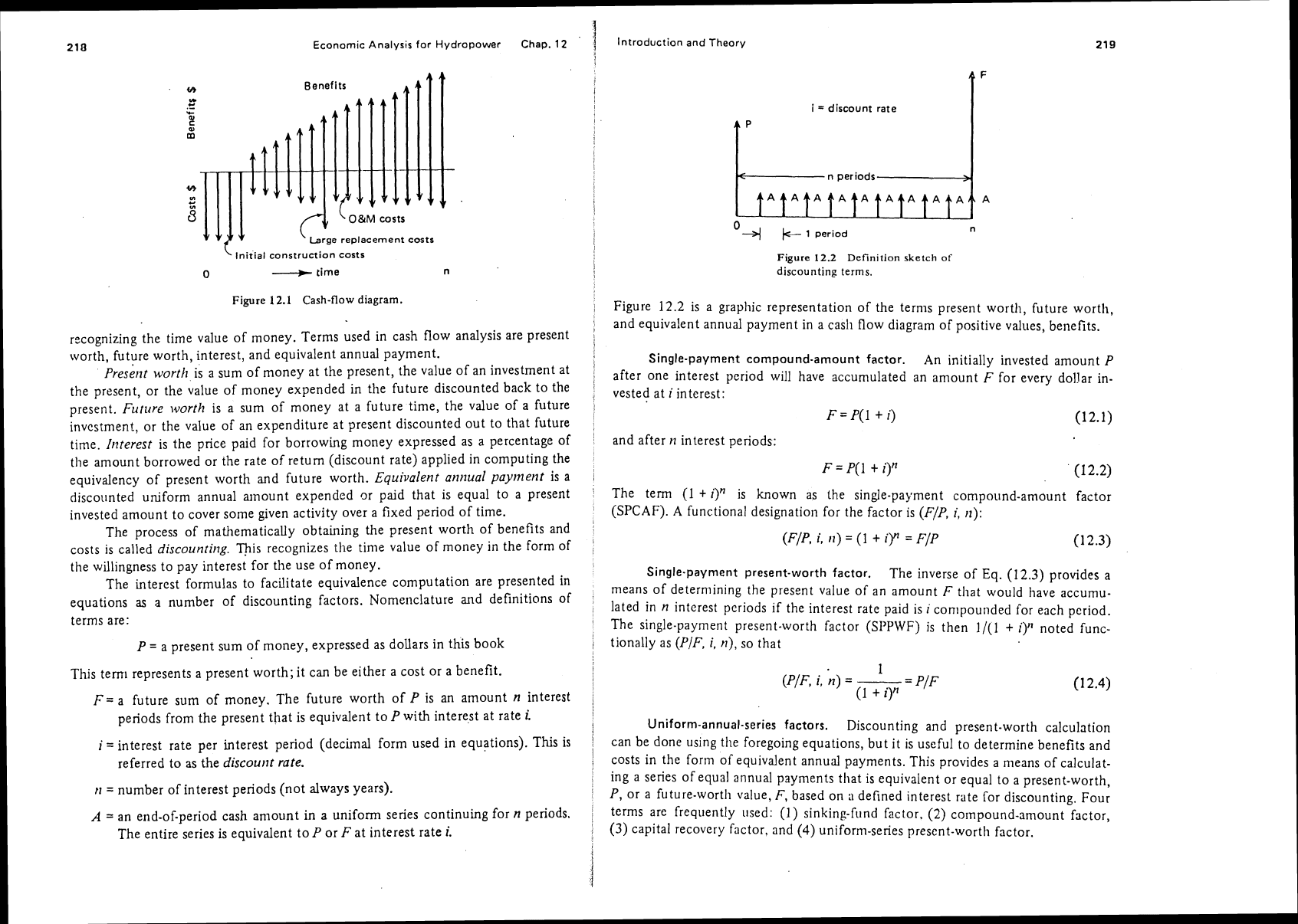
Cash flow is the expenditure (costs) and receipts or values obtained (benefits)
over time that are directly related to a given enterprise or project development. A
cash flow diagram is a graphic representation of cash flow with
~nagnitude of ex-
penditures and receipts plotted vertically
and time represented
on
the horizontal
scale. Figure 12.1 is
a
typical cash flow diagram. The benefits (reccipts) are repre-
sented by upward arrows
and costs (expenditures) are represented by downward
arrows. The distance along the
liorizontal scale represents time.
The basic idea for economic equivalency calculations is to convert the value
of benefits and costs that occur at different times to equivalent monetary amounts,
Economic
Analysis
for Hydropower
Chap.
12
1
Introduction
and
Theory
,
Initial
construction
costs
0
---9-
time
tft
YI
.d
.-
5
m
t
A
A"
Figure
12.1
Cash-flow
diagram.
t9
yl
4-
B
recognizing
the time value of money. Terms used in cash flow analysis are present
worth, future worth, interest, and equivalent annual payment.
~reseilt worth
is a sum of money at the present, the value of an investment at
the present, or the value of money expended in the future discounted back to the
present.
Future worth
is a sum of money at a future time, the value of
a
future
investment, or the value of an expenditure at present discounted out to that future
time.
b~terest
is the price paid for borrowing money expressed as a percentage of
the amount borrowed or the rate of return (discount rate) applied in computing the
equivalency of present worth and future worth.
Equivalent at~rlual paylnent
is a
discounted
uniform annual amount expended or paid that is equal to a present
invested amount to cover some given activity over a fixed period of time.
The process of mathematically obtaining the present worth of benefits and
costs is called
discounting.
This recognizes the time value of money in the form of
the willingness to pay interest for the use of money.
The interest formulas to facilitate equivalence computation are presented in
equations
as
a number of discounting factors. Nomenclature and definitions of
terms are:
vyv
P
=
a present sum of money, expressed as dollars in this book
v
vrv
brge
replacement
costs
This tern1 represents a present worth; it can be either a cost or a benefit.
F=
a future sum of money. The future worth of
P
is an amount
n
interest
periods from the present that is equivalent to
P
with interest at rate
i.
i
=
interest rate per interest period (decimal form used in equations).
This
is
referred to as the
discourlr
rate.
tt
=
number of interest periods (not always years).
A
=
an end-of-period
cash
amount in
a
uniform series continuing for
n
periods.
The entire series is equivalent to
P
or
F
at interest rate
i.
A
F
i
=
discount rate
A
P
4
n
periods
>
0
4
/c-
1
period
n
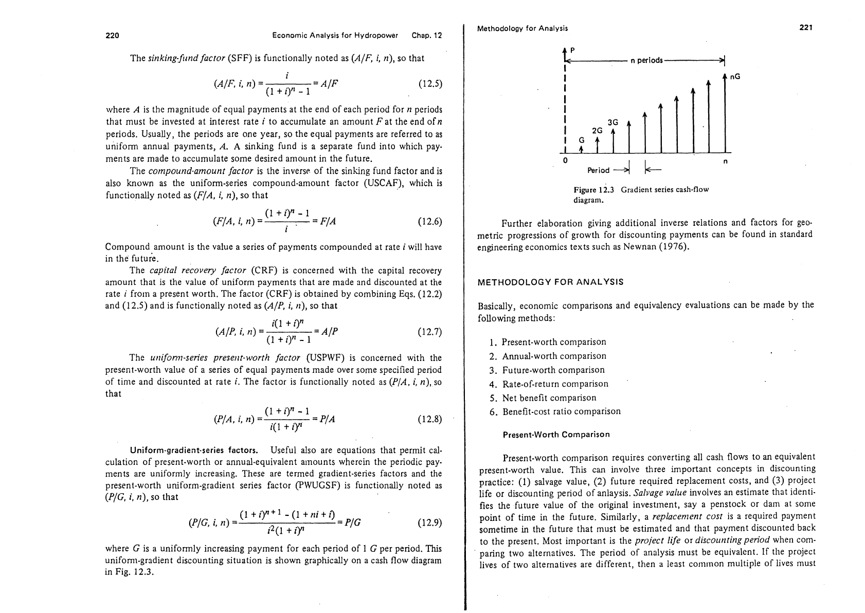
Figure
12.2
Definition
sketch
of
discounting
terms.
Figure
12.2
is a graphic representation of the terms present worth, future worth,
and equivalent annual payment in a
cash flow diagram of positive values, benefits.
Single-payment compound-amount factor.
An initially invested amount
P
after one interest period will have accumulated an amount
F
for every dol!ar in-
vested at
i
interest:
and after
tl
interest periods:
The
term
(1
+
i)"
is
known as the single-payment compound-amount factor
(SPCAF).
A
functional designation for the factor is (F/P,
i,
it):
1
(F/P,
i,
it)
=
(1
+
i)"
=
F/P
(1
2.3)
Single-payment present-worth factor.
The inverse of Eq.
(12.3)
provides a
means of determining the present value of an amount
F
that would have accumu-
lated in
n
interest periods if the interest rate paid is
i
con~pounded for each period.
The single-payment present-worth factor (SI'PWF) is then
1/(1
+
i)"
noted func-
tionally as
(PIF,
i,
n),
so that
Uniform-annual-series factors.
Discounting and present-worth calculation
can be done using
the foregoing equations, but it is useful to determine benefits and
costs in the form of equivalent annual payments. This provides a means of calculat-
ing a series of equal annual payments that is equivalent or equal to a present-worth,
P,
or a future-worth value,
F,
based on
n
defined interest rate for discounting. Four
terms are frequently used:
(1)
sinking-fund factor.
(2)
co~npound-amount factor,
(3)
capital recovery factor, and
(4)
uniform-series present-worth factor.
220
Economic Analysis for Hydropower Chap.
12
The sinking-firnd factor (SFF) is functionally noted as
(AlF,
i, n), so that
i
(A/F,
i,
n)
=
=
A/F
(1
t
i)"
-
1
where
A
is the magnitude of equal payments at the end of each period for n periods
that must be invested at interest rate
i
to accumulate an amount
F
at the end of
n
periods. Usually, the periods are one year, so the equal payments are referred to as
uniform annual payments, A.
A
sinking fund is a separate fund into which pay-
ments are made to accumulate some desired amount in the future.
The compound-amount factor is
the inverse of the sinking fund factor and is
also known as the uniform-series compound-amount factor (USCAF), which is
functionally noted
as
(FIA,
i,
n), so that
Compound amount is the value a series of payments compounded at rate i will have
in the future.
The capital recovery factor (CRF) is concerned with the capital recovery
amount that is the value of uniform payments that are made and discounted at the
rate
i
from a present worth. The factor (CRF) is obtained by combining Eqs. (12.2)
and (12.5) and is functionally noted as
(A/P, i, n), so that
The
unifon?z-series preserzr-worth factor (USPWF) is concerned with the
present-worth value of a series of equal payments made over some specified period
of
time and discounted at rate
i.
The factor is functionally noted as (PIA, i, n), so
that
Uniform-gradient-series factors. Useful also are equations that permit cal-
culation of present-worth or annual-equivalent amounts wherein the periodic pay-
ments are uniformly increasing. These are termed gradient-series factors and the
present-worth uniform-gradient series factor (PWUCSF) is functionally noted as
(PIG, i, n), so that
(1
t
i)"+l
-(1
+nit
i)
(PIG,
i,
n)
=
=
PIG
i2(1
t
i)"
where G is a uniformly increasing payment for each period of
1
G
per period. This
unifornl-gradient discounting situation is shown graphjcally on a cash flow diagram
in Fig. 12.3.
Methodology for Analysis
0
Period
-4
n
Figure
12.3
Gradient series
cash-flow
diagram.
Further elaboration giving additional inverse relations and factors for geo-
metric progressions of growth for discounting payments can be found in standard
engineering economics texts such as Newnan (1976).
METHODOLOGY
FOR
ANALYSIS
Basically, economic comparisons and equivalency evaluations can be made by the
following methods:
1.
Present-worth comparison
2.
Annual-worth comparison
3.
Future-worth comparison
4.
Rate-of-return comparison
5.
Net benefit comparison
6. Benefit-cost ratio comparison
Present-Worth Comparison
Present-worth comparison requires converting all cash flows to an equivalent
present-worth value. This can involve three important concepts in discounting
practice: (1) salvage value,
(2)
future required replacement costs, and
(3)
project
life or discounting period of anlaysis. Salvage value involves an estimate that identi-
fies the future value of the original investment, say a penstock or dam at some
point of
time in the future. Similarly, a replacement cost is a required payment
sometime
in
the future that must be estimated and that payment discounted back
to the present. Most important is the project life or
disco~triringpen'od when com-
paring two alternatives. The period of analysis must be equivalent.
If the project
lives of two alternatives are different, then
a
least common multiple of lives must
222
Economic
Analysis
for Hydropower
Chap.
12
bc used and identical
replacement
consideratiori made. This requires a calculation
of periodic
rcinvestriient for the least conunon time. To illustrate the principle of
present-worth comparison, a brief example of an economic analysis of a component
portion of a hydropower plant is presented.
Example
12.1
Given:
Alternative A, long penstock:
Initial investment
$5 10,000
Useful life
30
yr
Salvage value at
30
yr
$50,000
Alternative
B,
canal and short penstock:
Initial investment cost
$520,000
Useful life
45
yr
Canal gate replacement cost
$30,000
every
15
yr
Salvage value at
45
yr
$70,000
Required:
Make
a
present-worth comparison of the two alternatives. Consider
interest rate
i
=
10%.
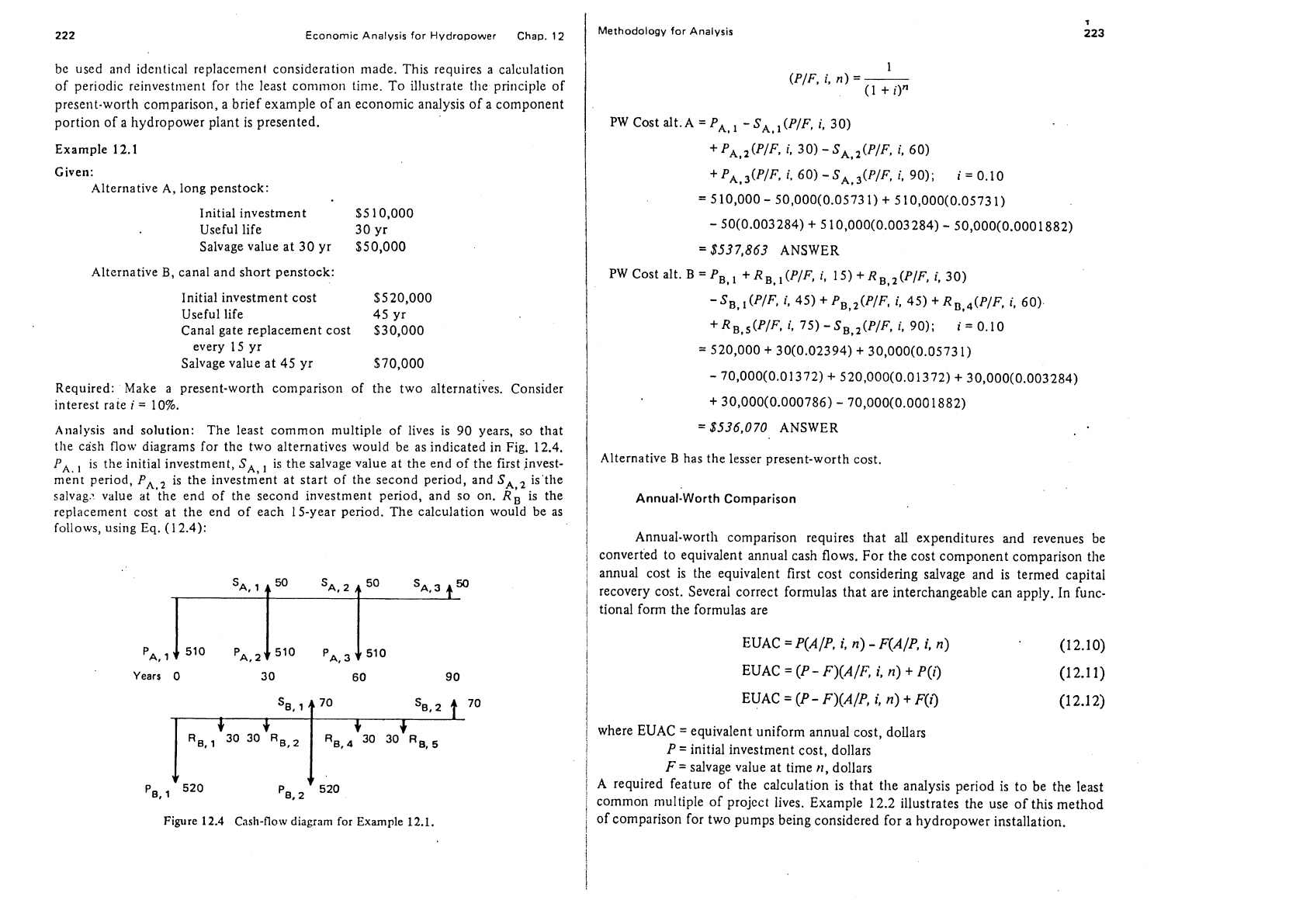
Analysis and solution:
The least common multiple of lives is
90
years, so that
the cash flow diagrams for the two alternatives would be as indicated in Fig.
12.4.
PA,
is the initial investment,
SA,
,
is the salvage value at the end of the first invest-
ment period,
PAVz
is the investment at start of the second period, and
SA,2
is'the
salvag: value at the end of the second investment period, and so on.
RB
is the
replacement cost at the end of each 15-year period. The calculation would
be
as
follows, using Eq.
(1
2.4):
Years
0
3
0
60
90
Figure
12.4
Cash-flow diagram for
Example
12.1.
Methodology for
Analysis
PW Cost a1t.A
=PA,1 -SA,I(P/F,
i,
30)
+pA,l(p/F,
i,
30)-SA,2(P/F,
i,
60)
+
PA,,(P/F,
i,
60)
-
SA,3(P/F,
i,
90);
i
=
0.10
=
S
10,000
-
50,000(0.0573
1)
+
S
10,000(0.0573
1)
-
50(0.003284)
+
5 10,000(0.003284)
-
50,000(0.0001882)
=
$537,863 ANSWER
PWCost
alt.B=PB,l +RB,,(P/F,
i,
lS)+RB,l(P/F,
i,
30)
-SB,l(P/F,
i,
45) +PB,2(P/F,
i,
45)
+
RDS4(P/F,
i,
60)
+RB,,(P/F,
i,
75)-S,,,(P/F,
i,
90);
i=
0.10
=
520,000
+
30(0.02394)
+
30,000(0.05731)
-
70,000(0.01372)
+
520,000(0.01372)
+
30,000(0.003284)
+
30,000(0.000786)
-
70,000(0.0001882)
=
$536,070 ANSWER
Alternative
B
has the lesser present-worth cost.
Annual-Worth Comparison
Annual-worth comparison requires that
all
expenditures and revenues be
converted to equivalent annual cash flows. For the cost component comparison the
annual cost is the equivalent first cost considering salvage and is termed capital
recovery cost. Several correct formulas that are interchangeable can apply.
In
func-
tional form the formulas are
EUAC
=
P(A/P,
i,
n)
-
F(A/P,
i,
n)
'
(12.10)
EUAC
=
(P
-
F)(A/F,
i,
n)
+
P(i)
(12.11)
EUAC
=
(P
-
F)(A/P,
i,
n)
+
F(i)
(12.12)
where EUAC
=
equivalent uniform annual cost, dollars
P
=
initial investment cost, dollars
F
=
salvage value at time
n,
dollars
A required feature of the calculation is that the analysis period is to be the least
common multiple of
projcct lives. Example
12.2
illustrates the use of this method
of comparison for two pumps being considered for a hydropower installation.
224
Economic
Analysis
for Hydropower Chap.
12
Example
12.2
.
Given: Two pumps:
Pump
A
Pump
B
'
First cost
$7000 $5000
Salvage
value
$1500 $1000
Useful life
12
yr
6
yr
Assume that interest rate
i
=
7
%.
Required: Determine the most economical purchase.
Analysis and solution: Using Eqs.
(12.7)
and
(12.12),
we have
EUAC,,
=
(P
-
F)(A/P,
i,
n)
+
F(i)
n
=
12,
i
=
0.07
=
(7000
-
1500)(0.1259)
+
1500(0.07)
=$797
ANSWER
EUACB
=
(P- F)(A/P,
i,
n) +F(i)
n =6,
i
=
0.07
=
(5000
-
1000)(0.2098)
+
1
OOO(0.07)
=
$909
ANSWER
For an
n
=
12
periods of analysis for pump
B,
use Eqs.
(1
2.4)
and
(12.7):
EUACB
=
[P
-
F(P/F, i, n)
+
P(P/F, i, n)]
iz0.07, n=6 i=0.07, n=6
-
F(P/F, i, n)l [(Alp, i, n)l
i
=
0.07,
n
=
12
EUACB
=
[5000
-
(1000)(0.6663)
+
SOOO(0.6663)
-
1
OOO(O.444O)I [0.1259]
=
$909
ANSWER
The two approaches give the same result for pump
B
for 6-year and 12-year analyses
as long as there is identical replacement of the pump at the end of each 6-year
period. If that
assuniption is not valid, it is necessary to use least common multiple
lives or lives that arc
coterminous
with appropriate recognition of respective salvage
values.
Methodology for Analysis
225
Future-Worth Comparison
Future-worth comparisons require that a future date be selected for alterna-
tives to be terminated or compared on and the cash flows projected into future
dollars of value, giving due regard for intermediate replacement costs, salvage
values, and periods of useful life. The usual discounting factors can be used.
Rate-of-Return Comparison
The rate-of-return (ROR) method of economic comparison or evaluation
calculates the interest rate on unrecovered investment such that the payment
schedule (schedule of return or project analysis period) makes the unrecovered
investment equal to zero at the end of the useful life of the investment. In public
investment economics the rate of return refers to internal rate of return. Also, the
rate of return may refer to rate of return over investment:
Annual net (Benefits
-
Costs)
,
Investment
This is often used by public service commissions to set permitted rates.
ROR
is the
interest rate tllat makes the sirnu of the present wort/~s of expetzditures and pay-
ments equal to zero, or
CPW
=
0,
and it is the interest rate at rvhich benefits equal
costs or the net benefits equal zero.
The method requires a trial-and-error approach.
The computations may be carried out
in
either present-worth configuration or in
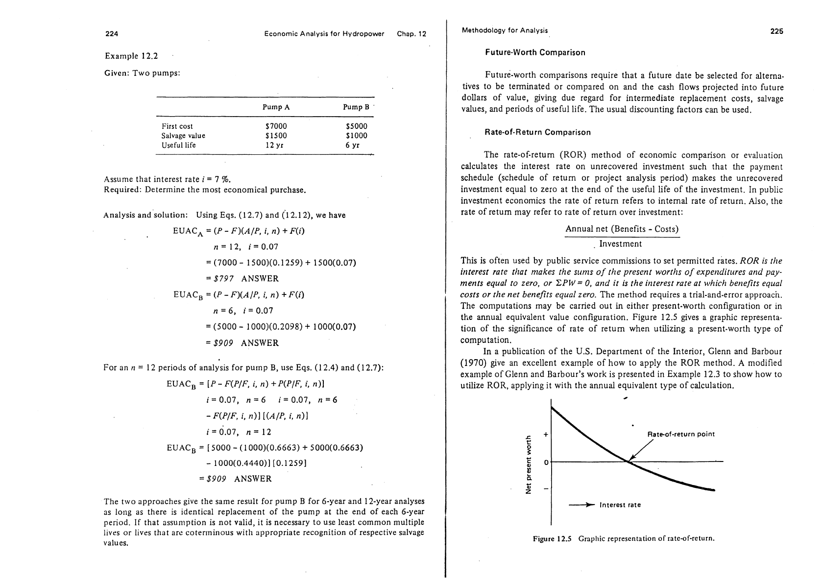
the annual equivalent value configuration. Figure
12.5
gives a graphic representa-
tion of the significance of rate of return when utilizing a present-worth type of
computation.
In a publication of the
U.S.
Department of the Interior, Glenn and Barbour
(1970)
give an excellent example of how to apply the ROR method.
A
modified
example of Glenn and Barbour's work is presented in Example
12.3
to show how to
utilize ROR, applying it with the annual equivalent type of calculation.
I
4
---t
Interest rate
Figure
12.5
Graphic representation of rate-of-return.
!
Methodology for Analysis
226
Economic Analysis for Hydropower Chap.
12
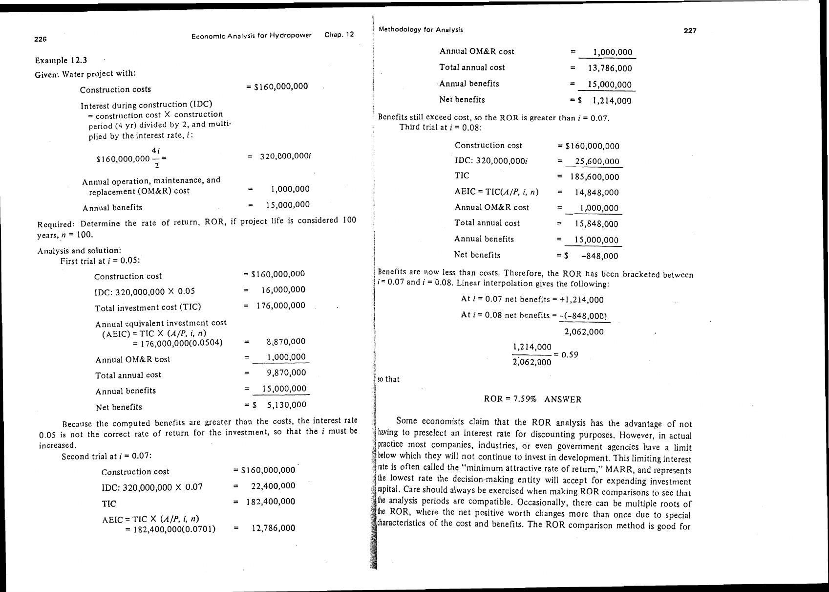
Annual OM&R cost
=
1.000.000
Total annual cost
=
13,786,000
Given: Water project with:
Annual benefits
=
15,000,000
Net benefits
=
$
1,214,000
Construction costs
=
%
160,000,000
Interest during construction
(IDC)
=
construction cost
X
construction
period
(4
yr) divided by
2,
and
multi-
plied by the interest rate,
i:
Benefits still exceed cost, so the ROR is greater than
i
=
0.07.
Third trial at
i
=
0.08:
Construction cost
=
$160,000,000
IDC:
320,000,000i
=
25,600,000
TIC
=
185,600,000
AEIC
=
TIC(A/P,
i,
n)
=
14,848,000
Annual operation, maintenance, and
replacement
(OM&R) cost
=
1,000,000
Annual benefits
=
15,000,000
Annual
OM&R cost
=
1,000.000
Required: Determine the rate of return, ROR, if project life is considered 100
years, n
=
100.
Total annual cost
=
15,848,000
Annual benefits
=
15,000,0013
Net benefits
=
$
-848,000
Analysis and solution:
First trial at
i
=
0.05:
!
Bonefits are now less than costs. Therefore, the ROR has been bracketed between
1
i=
0.07 and
i
=
0.08. Linear interpolation gives the following:
i
Construction cost
=
$160,000,000
IDC:
320,000,000
X
0.05
=
16,000,000
5
At
i=
0.07 net benefits
=
+1,214,000
Total investment cost (TIC)
=
176,000,000
At
i=
0.08 net benefits
=
-(-848,000)
2,062,000
Annual equivalent investment cost
(AEIC)
=
TIC
X
(Alp,
i,
n)
=
176,000,000(0.0504)
=
8,870,000
Annual
OM&R Cost
=
1,000,000
Total annual cost
=
9,870,000
so
that
ROR
=
7.59% ANSWER
Annual benefits
Net benefits
Because
tlie computed benefits are greater than the costs, the interest rate
0.05 is not the correct rate of return for the investment, so that the
i
must be
increased.
Second trial at
i
=
0.07:
Some economists claim that the ROR analysis has the advantage of not
having to preselect an interest rate for discounting purposes. However, in actual
practice most companies, industries, or even government agencies have
a
limit
below which they will not continue to invest
in
development. This limiting interest
rate is often called the "minimum attractive rate of return," MARR, and represents
Ihe
lowest rate the decision-making entity will accept for expending investment
eapital. Care should always be exercised when making
ROR
comparisons to see that
he
analysis periods are compatible. Occasionally, there can be multiple roots of
he
ROR, where the net positive worth changes more than once due to special
characteristics of the cost and benefits. The ROR comparison method is good for
Construction cost
=
S
160,000,000
IDC:
320,000,000
X
0.07
=
22,400,000
TIC
=
182,400,000
AEIC
=
TIC
X
(Alp,
i,
n)
=
182,400,000(0.0701)
=
12,786,000