Warnick C.C. Hydropower engineering
Подождите немного. Документ загружается.

168
Pressure Control and Speed Regulation Chap.
10
Hydraulic gradient
of pressure rise
\-.--+
t~h maximum
_____------
pressure rise
_
__-
--
-
---.I
-
I---
-
-
-__
-
----
-Ah maximum
Hydraulic gradient pressure drop
of pressure drop
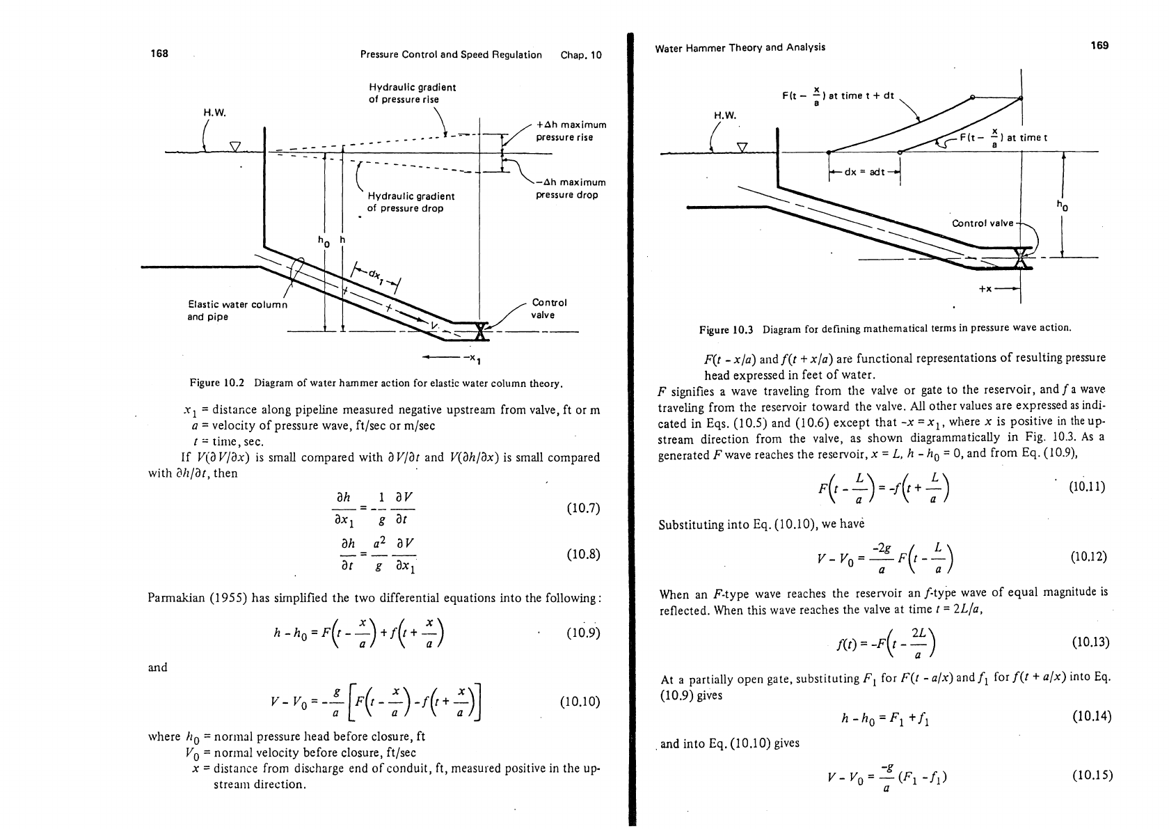
Figure
10.2
Diagram of water hammer action for elastic water column theory.
xl
=
distance along pipeline measured negative upstream from valve, ft or
rn
a
=
velocity of pressure wave, ft/sec or m/sec
t
=
time, sec.
If Via Ylax) is small compared with
a
Vlat and Y(ah/ax) is small compared
with
Shlat,
then
ah
iav
-
-----
ax,
g
at
ah
a2
av
-
----
at
g
ax,
Parmakian (1 955) has simplified the two differential equations into the following
:
and
where
ho
=
normal pressure head before closure, ft
Yo
=
normal velocity before closure, ft/sec
x
=
distance from discharge end of conduit,
ft,
measured positive
in
the up-
stream direction.
Water Hammer Theory and Analysis
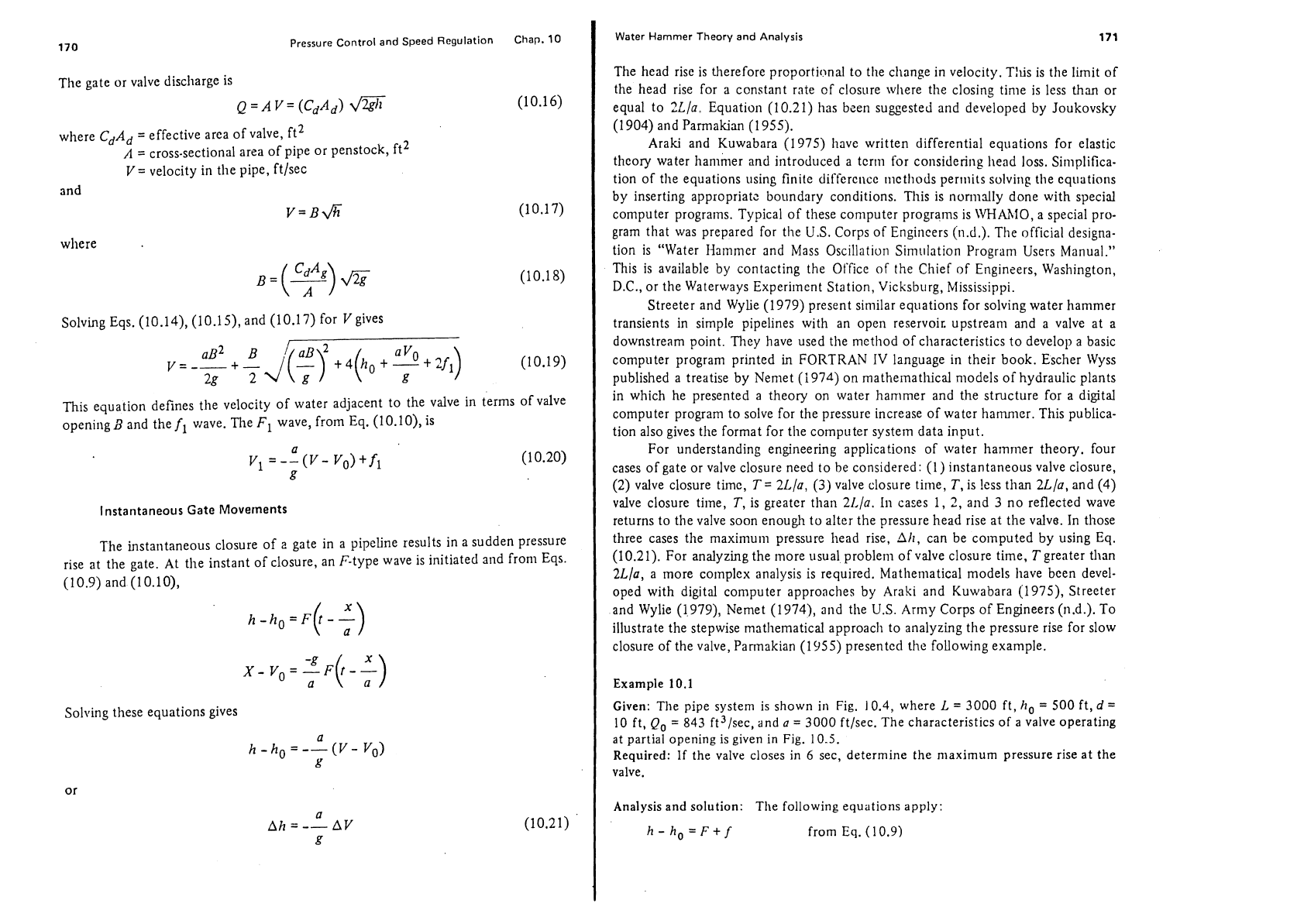
Figure
10.3
Diagram
for defining mathematical terms in pressure wave action.
F(t
-
x/a) and f(t
+
x/a) are functional representations of resulting pressure
head expressed in feet of water.
F
signifies a wave traveling from the valve or gate to the reservoir, and
f
a
wave
traveling from the reservoir toward the valve.
All other values are expressed
as
indi-
cated in Eqs. (10.5) and (10.6) except that
-x
=xl,
wliere x is positive in the up-
stream direction from the valve, as shown diagrammatically in Fig. 10.3. As a
generated
F
wave reaches the reservoir,
x
=
L,
h
-
ho
=
0, and from
Eq.
(10.9),
Substituting into
Eq.
(10.10), we
have
When an F-type wave reaches the reservoir an f-type wave of equal magnitude
is
reflected. When this wave reaches the valve at time
t
=
2L/a,
At a partially open gate, substituting
FI
for
F(r
-a/x) and
fl
for f(t
+
a/x) into
Eq.
(10.9) gives
h-ho=Fl +fl (10.14)
and into
Eq.
(10.10) gives
170
Pressure
Control and Speed Regulation
Chap.
10
The gate or valve discharge is
QZAV=(CdAd) (10.16)
where
CdAd
=
effective area of valve, ft2
A
=
cross-sectional area of pipe or penstock, ft2
V
=
velocity in the pipe, ft/sec
and
V=B&
(10.17)
Solving Eqs.
(10.14), (10.15), and (10.17) for V gives
This equation defines the velocity of water adjacent to the valve in terms of valve
opening
3
and the
fl
wave. The
F1
wave, from Eq. (10.10), is
Instantaneous Gate
Movements
The instantaneous closure of
z
gate in a pipeline results in a sudden pressure
rise at the gate. At the instant of closure, an
F-type wave is initiated and from Eqs.
(10.9) and
(10.10),
Solving these equations gives
a
h
-ho
=
--
(V- Vo)
k!
Water Hammer Theory and Analysis
171
The head rise is therefore proportirlnal to the change in velocity. Tllis is the limit of
the head rise for a constant
rate cf closure where the closing time is less
than
or
equal to
Xla. Equation (10.21) has bcen suggested and developed by Joukovsky
(1 904) and Parmakian (1 955).
Araki and Kuwabara (1975) have written differential equations for elastic
theory water
han~her and introduced a term for considering head loss. Simplifica-
tion of
the equations using finite differcl~cc
neth hods
permits solving the equations
by inserting appropriatz boundary conditions. This is
nonnally done with special
computer programs. Typical of these computer programs is
\VHhhfO, a special pro-
gram that was prepared for the U.S. Corps of Engineers
(11.d.). The official designa-
tion is "Water
Ilarnmer and Mass Oscillation Simr~lation Program Users Manual."
This is available by contacting the Office of the Chief of Engineers, Washington,
D.C., or the Waterways Experiment Station,
Vicksburg, Mississippi.
Streeter and Wylie (1979) present similar equations for solving water hammer
transients in simple pipelines with an open reservoir. upstream and a valve at a
downstream point. They have used
the mcthod of characteristics to develop a basic
computer program printed in FORTRAN
IV
language in their book. Escher Wyss
published a treatise by Nemet (1974) on
mathemathical nlodeIs of hydraulic plants
in which he presented a theory on water hammer and the structure for a digital
computer program to solve for the pressure increase of water
hammer. This publica-
tion also gives the format for the computer system data input.
For understanding engineering applications of water
harnrner theory. four
cases of gate or valve closure need to be considered: (1) instantaneous valve closure,
(2) valve closure tirnc,
T
=
2Ld/a,
(3)
valve closure tirne,
T,
is !ess than 2L/a, and (4)
valve closure
time,
T,
is greater than 2IJa.
In
cases 1,
2,
and
3
no reflected wave
returns to
the valve soon enough to alter the pressure head rise at the valve. In those
three cases the maximum pressure head rise, Ah, can be computed by using
Eq.
(10.21). For analyzing the more usual problem of valve closure time,
T
greater than
2L/a, a Inore cornplex analysis is required. Mathematical models have bcen devel-
oped with digital computer approaches by Araki and Kuwabara
(1975), Streeter
and Wylie (1,979), Nemet (1974), and the
U.S.
Army Corps of Engineers (11.d.). To
illustrate the
stepwise mathematical approach to analyzing the pressure rise for slow
closure of the valve, Pannakian (1955) presented the following example.
Example
10.1
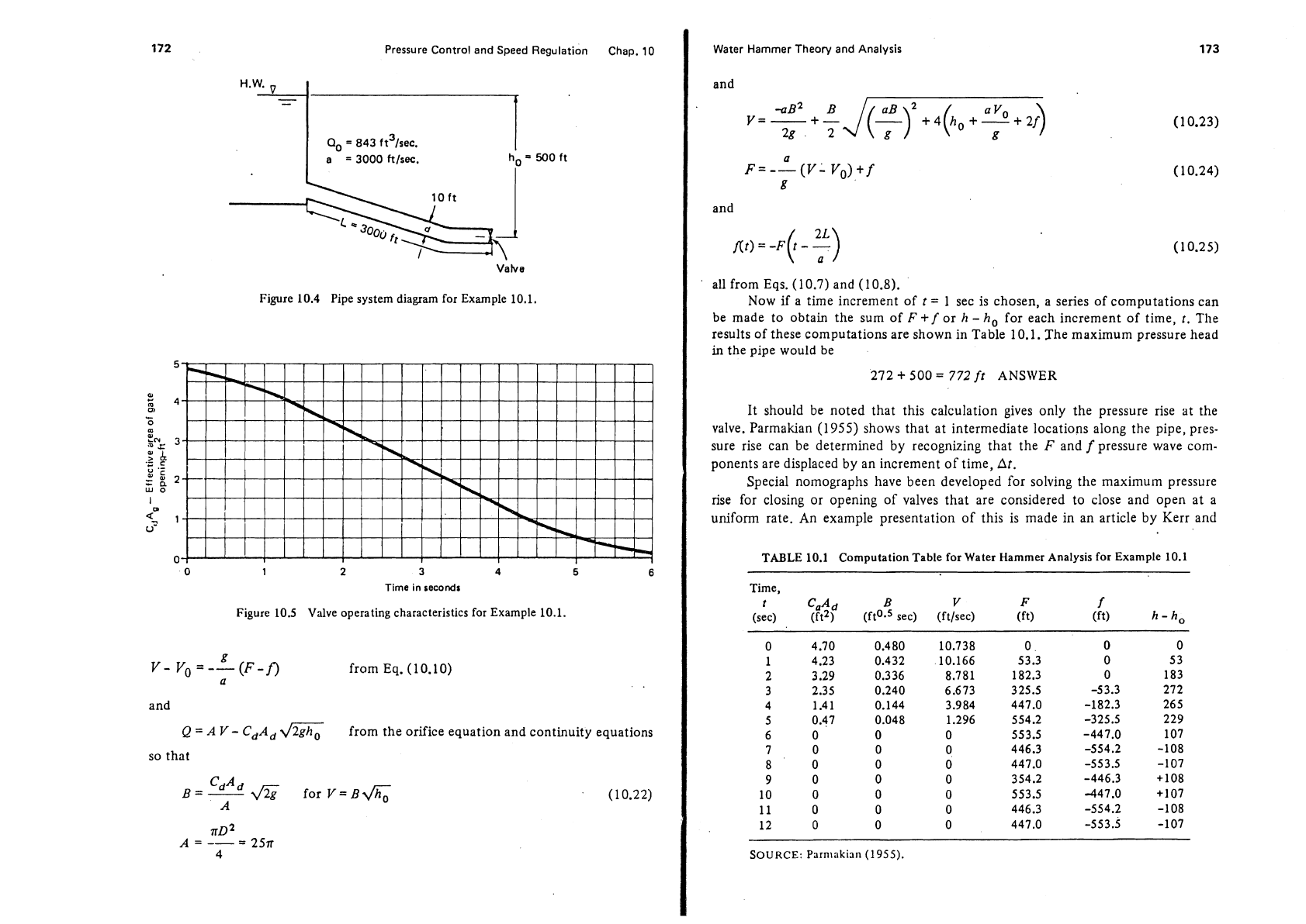
Given: The pipe system is shown in Fig. 10.4, where
L
=
3000 ft,
ho
=
500 ft,
d
=
10 ft,
Q0
=
843 ft3/sec, and
a
=
3000 ftjsec. The characteristics of a valve operating
at
partial opening is given in
Fig.
10.5.
Required:
If
the valve closes in
6
sec, determine the maximum pressure rise at the
valve.
Analysis and solution: The following equations apply:
h-ho=F+f
from Eq. (1 0.9)
172
Pressure Control and Speed Regulation Chap.
10
H.W.
91
Figure
10.4
Pipe system diagram for Example
10.1.
5
a2
s
4
m
-
0
m
$NC
3
.-
:
i
U
.-
;;2
WO
I
w
5.
1
u-
0
0
1
2
3
4
5
6
Time
in
seconds
Figure
10.5
Valve operating characteristics for Example
10.1.
g
V-
Vo=--(F-f)
from Eq. (10.10)
a
and
Q
=
A
V
-
CdAd
a
from the orifice equation and continuity equations
so that
Water Hammer Theory and
Analysis
and
and
all from Eqs. (1 0.7) and (1 0.8).
Now if a time increment of
t
=
1 sec is chosen, a series of computations can
be made to obtain the sum of
F
+
f
or h
-
ho for each increment of time,
r.
The
results of these computations are shown in Table 10.1. The maximum pressure head
in
the pipe would be
272
+
500
=
772
ft
ANSWER
It should be noted that this calculation gives only the pressure rise at the
valve. Parmakian (1955) shows that at intermediate locations along the pipe, pres-
sure rise can be determined by recognizing that the
F
and
f
pressure wave com-
ponents are displaced by an increment of time,
At.
Special nomographs have been developed for solving the maximum pressure
rise for closing or opening of valves that are considered to close and open at a
uniform rate. An example presentation of this is made in an article by Kerr and
TABLE
10.1
Computation Table for Water Hammer Analysis for Example
10.1
Time,
t
CaA
d
B
V
F
f
(sec) (It2) (ft0a5 sec) (ftlsec) (ft)
(ft)
h-ho
0 4.70 0.480 10.738 0 0 0
1 4.23 0.432 10.166 53.3 0 53
2
3.29 0.336 8.781 182.3 0 183
3 2.35 0.240 -53.3 272
6.673 325.5
4 1.41
0.144 3.984
447.0
-182.3 265
5 0.47 0.048
1.296
554.2 -325.5
229
6
0
0
0
553.5 -447.0
107
7 0 0
0
446.3 -554.2
-108
8 0 0
0
447.0
-553.5 -107
9 0 0
0
354.2 -446.3
+lo8
10 0 0
0
553.5
-447.0
+lo7
11 0
0 0
446.3 -554.2
-108
12 0
0 0
447.0
-553.5 -107
SOURCE:
Parnlnkian
(1955).
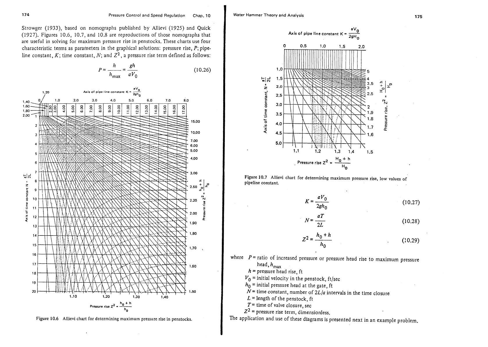
174 Pressure Control and Speed Regulation Chap. 10
Strowger (1933), based on nornographs publislled by Nlievi
(1925)
and Quick
(1927). Figures
10.6,
10.7, and 10.8 are reproductions
of
those nomograplls that
are useful in solving for
~naxirnum pressure rise
in
penstocks. These charts use four
cllaracteristic terms as parameters in the graphical solutions: pressure rise,
P;
pipe-
line constant,
K;
time constant,
N;
and
Z2,
a pressure rise term defined as follows:
Axis
of
pipe line
constant
K
=
5
7'
1.0
2gh0
,
A,
0. 2.0 3.0
4.0 5.0
6.0
7.0
8.0
1.10 1.20 1.30
1140
'
ha
+
h
Pressure rise
2'
-
-
Figure
10.6
Allievi chart for determining maximum pressure rise in penstocks.
Water Hammer Theory and Analysis
Axis
of
pipe line constant
K
=
-
2gH0
H,,
+
h
Pressure rise
z2
=
-
"0
Figure
10.7
Allievi chart for determining maximum pressure rise, low values of
pipeline constant.
where
P=
ratio of increased pressure or pressure head rise to maximum pressure
head,
hm,
h
=
pressure head rise, ft
Vo
=initial velocity in the penstock, ftlsec
ho
=
initial pressure head at the gate, ft
N=
time constant, number of
2L/a
intervals
in
the time closure
L
=
length of the penstock, ft
T=
time of valve closure, sec
z2
=
pressure rise term, dimensionless.
The application and use of these diagrams is presented next in an example problem.
Pressure Control and Speed Regulation
Chap.
10
Value of
P=
=
*
hm,, avo
Figure
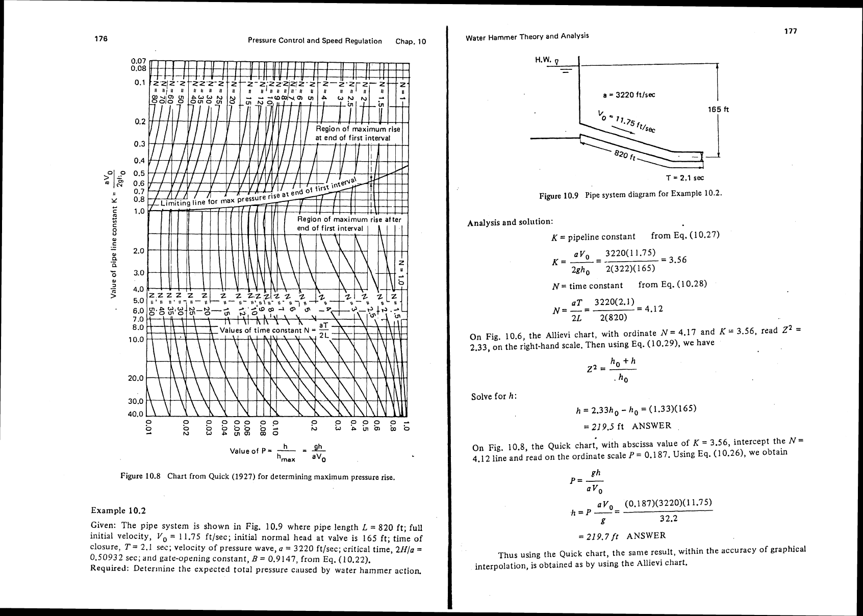
10.8
Chart from Quick (1927) for determining maximum pressure rise.
Example
10.2
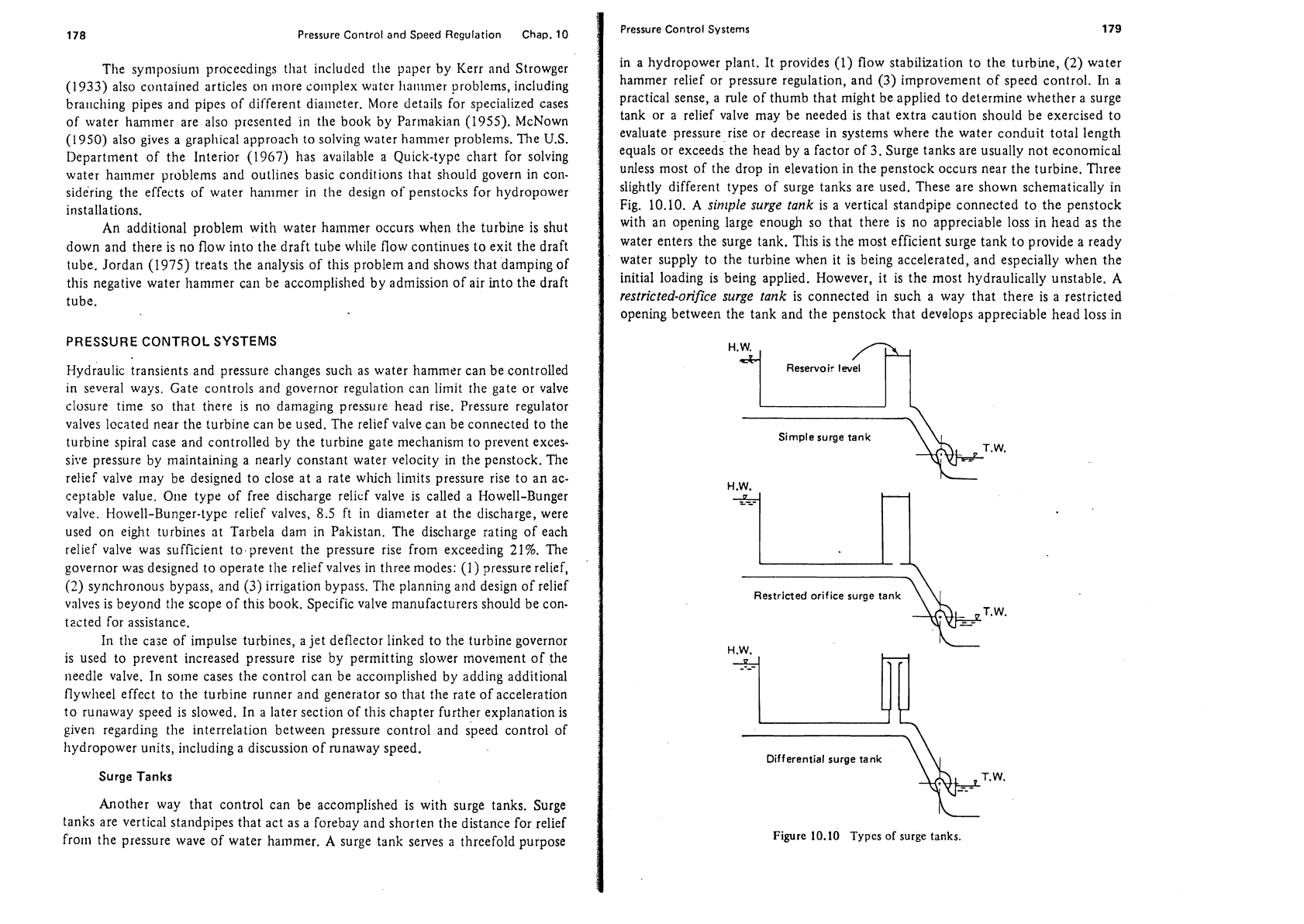
Given: The pipe system
is
shown
in
Fig. 10.9 where pipe length
L
=
820 ft; full
initial velocity,
Vo
=
11.75 ft/sec; initial normal head at valve is 165 ft; time of
closure,
T
=
2.1 sec; velocity of pressure wave,
a
=
3220 ftlsec; critical time, 2H/a
=
0.50932
sec; and gatr-opening constant,
D
=
0.9147, froin
Eq.
(I 0.22).
Required: Determine the expected total pressure
caused by water hammer action.
Water Hammer Theory and Analysis
T
=
2.1
sec
Figure
10.9
Pipe system diagram for Example 10.2.
Analysis and solution:
K
=
pipeline constant
from
Eq.
(1
0.27)
avo
-
3220(11.75)
K=
---
=
3.56
2gho 2(322)(165)
N=
time constant
from
Eq.
(1 0.28)
aT 3220(2.1)
N=-=
=
4.12
2L
2(820)
On Fig. 10.6, the Allievi chart, with ordinate
iV=
4.17 and
K
=
3.56, read
z2
=
2.33, on the right-hand scale. Then using
Eq.
(1 0.29), we have
ho+h
22
=
-
.
ho
Solve for
h
:
h
=
2.33ho
-
ho
=
(1,33)(165)
=
21
9.5
ft
ANSWER
On Fig. 10.8, the Quick chart, with abscissa value of
K
=
3.56, intercept the
N=
4.12 line and read on the ordinate scale
P
=
0.1 87. Using
Eq.
(1
0.26), we obtain
ph
p=
-
a
Vo
avo- (0.1 87)(3220)(1 1.75)
h=P--
g
32.2
=
219.7
ft
ANSWER
Thus using the Quick chart, the same result, within the accuracy of graphical
interpolation, is obtained as by using the
Allievi chart.
178
Pressure Control and Speed Regulation Chap.
10
The syniposiuni proceedings that included t!le paper by Kerr and Strowger
(1933) also contained articles
on
more co~nplex water 11a111nler problems, including
bra~~cliing pipes and pipes of different diameter. More details for specialized cases
of
water hammer are also presented in the book by Par~nakian
(1955).
McNown
(1950) also gives a graphical approach to solving water hammer problems. The
U.S.
Department of the Interior (1967) has available a Quick-type chart for solving
water
hammer problems and outlines basic conditions that should govern in con-
sidering tlie effects of water
hammer in the design of penstocks for hydropower
installations.
An additional problem with water
hammer occurs when the turbine is shut
down and there is no flow into
the draft tube while flow continues to exit the draft
tube. Jordan (1975) treats the analysis of this problem and shows that damping of
tliis negative water hammer can be acconiplislied by admission of air into the draft
tube.
PRESSURE CONTROL SYSTEMS
Hydraulic transients and pressure changes such as water hammer can be controlled
in several ways. Gate controls and governor regulation can limit the gate or valve
closure time so that there is no damaging pressure head rise. Pressure regulator
valves located near the turbine can be used. The relief valve can be connected to the
turbine spiral case and controlled by the turbine gate
mecl~anism to prevent exces-
sive pressure by maintaining a nearly constant water velocity in the penstock. The
relief valve may be designed to close at a rate
wluch limits pressure rise to an ac-
ceptable value.
One type of free discharge relicf valve is called a Howell-Bunger
valve. Howell-Bunger-type relief valves,
8.5
ft in diameter at the discharge, were
used on eight
turbines at Tarbela dam in Pakistan. The discharge rating of each
relief valve was sufficient
to.prevent the pressure rise from exceeding 21%. The
governor was designed to operate tlie relief valves in three
modes:
(1)
pressure relief,
(2)
synchronous bypass, and
(3)
irrigation bypass. Tlie planniig and design of relief
vn1vt.s is beyond tlie scope of this book. Specific valve manufacturers should be con-
tected for assistance.
111 the case of impulse turbines, a jet deflector linked to the turbine governor
is used to prevent increased pressure rise by permitting slower
movement of the
needle valve. In some cases the control can be
acco~nplished by adding additional
flywheel effect to the turbine runner and generator so
that the rate of acceleration
to runaway speed is slowed. In a later section of
tliis chapter further explanation is
given regarding tlie interrelation between pressure control and speed control of
hydropower units, including a discussion of runaway speed.
Surge
Tanks
Another way that control can be accomplished is with surge tanks. Surge
tanks are vertical standpipes
that act as a forebay and shorten the distance for relief
from the pressure wave of water hammer.
A
surge tank serves a threefold purpose
Pressure Control Systems
179
in a hydropower plant. It provides
(1)
flow stabilization to the turbine, (2) water
hammer relief or pressure regulation, and
(3)
improvenlent of speed control. Iri a
practical sense, a rule of thumb that might be applied to determine whether a surge
tank or a relief valve may be needed is that extra caution should be exercised to
evaluate pressure rise or decrease in systems where the water conduit total length
equals or exceeds the head by a factor of
3.
Surge tanks are usually not economical
unless most of the drop in elevation in the penstock occurs near the turbine. Three
slightly different types of surge tanks are used. These are shown schematically in
Fig. 10.10.
A
simple surge
tank
is a vertical standpipe connected to the penstock
with an opening large enough so that there is no appreciable loss in head as the
water enters the surge tank. This is the most efficient surge tank to provide a ready
water supply to the turbine when it is being accelerated, and especially when the
initial loading is being applied. However, it is the most hydraulically unstable. A
restricted-orifce surge
tank
is connected in such a way that there is a restricted
opening between the tank and the penstock that develops appreciable head loss in
Simple surge tank
---y&+T.N
H.W.
L
Restricted orifice surge tank
&T-W.
Differential surge tank
q9yT.W.
Figure
10.10
Types of surge
tanks.
1
DO
Pressure Control and Speed Regulation Chap.
10
I
pressure Control
Systems
the water that flows into or out of the tank. Thus the orifice tank does not supply
or accept excess penstock flow, but it is
more hydraulically stable. The
differerttial
surge tarzk
is a combination of a simple tank and a restricted-orifice tank.
An
internal riser of smaller diameter than the full connection to the penstock is built
to extend up through the tank
while an outer tank is connected by a simple pipe
connection to tbe penstock. The riser
may also have a flow restrictor or orifice
inside. Thus one part of the tank responds with a minimum of head loss while the
outer tank offers resistance to rapid flow into the tank.
Simple Surge
Tank:
Theory
and~nal~sis
For simple surge tanks it is important to have analytical procedures for com-
puting the upsurge. Parmakian (1955) developed three fundamental equations
based on the assumptions that hydraulic losses are negligible in the simple surge
tank, the velocity head in the pipe can be neglected, and that rigid water column
theory of water
hammer is sufficient. This is justified if the pressure rise is small
and there is not appreciable stretching of the pipe nor compressing of the water.
The equations are
where
S
=
upsurge in surge tank above static level, ft
q0
=
water discharge in the pipe before closure, ft3/sec
AT
=
cross-sectional area of surge tank, ft2
L
=
length of pipe from surge tank to open water surface, ft
A,
=
cross-sectional area of pipe, ft2
g
=
acceleration of gravity, ft/sec2
t
=
time from instantaneous closure of valve, sec
T
=
time required to reach maximum upsurge in surge tank, sec
These last three equations can be useful for preliminary analysis and in cases where
the magnitude of hydraulic losses is small in
the portion of the penstock extending
upstream from the surge tank. For other cases where
head loss is considered signifi-
cant,
the
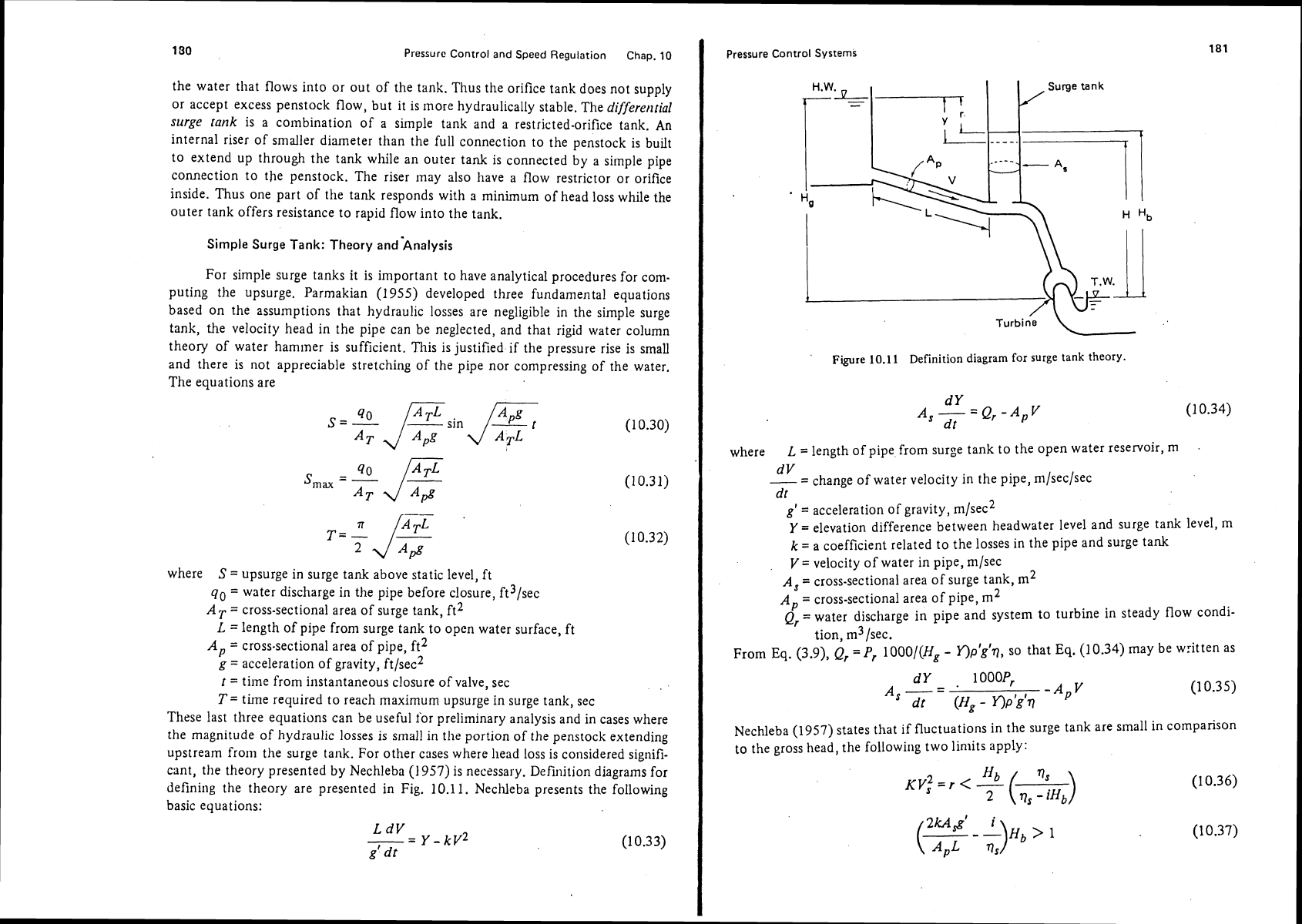
theory presented by Nechleba (1957) is necessary. Definition diagrams for
defining the theory are presented in Fig. 10.11. Nechleba presents the following
basic equations:
Turbine
L
I
'
Figure
10.11
Definition
diagram
for
surge
tank theory.
where
L
=
length of pipe from surge tank to the open water reservoir,
m
dV
-- -
change of water velocity in the pipe, m/sec/sec
d
t
g'
=
acceleration of gravity, m/sec2
Y
=
elevation difference between headwater level and surge tank level,
m
k
=
a coefficient related to the losses in the pipe and surge tank
V
=
velocity of water in pipe, rn/sec
A,
=
cross-sectional area of surge tank, m2
A,
=
cross-sectional area of pipe, m2
Qr
=water discharge in pipe and system to turbine in steady flow condi-
tion,
m31sec.
From Eq. (3.9),
Q,
=Pr
1000/(Hg
-
Y)P'~'~, so that
Eq.
(10.34) may be written as
Nechleba (1957) states that if fluctuations in the surge tank are small in comparison
to the gross head, the
followirlg two limits apply:
182
Pressure
Control
and
Speed
Regulation
Chap.
10
where
V,
=
~ncdium velocity of flow in the pipe upstream of tlie surge tank, ni/sec
Nb
=
pressure head to top surface of surge tank, In
vS
=
medium efficiency of the hydropower system at flow rate considered
i
=
dq/dH
=
change in system efficiency created by fluctuating head in
surge tank
r
=
liead loss in penstock upstream of surge tank, m.
Equation (10.36) dictates that losses in tlie pipe upstream of the surge tank, labeled
r
in Fig. 10.1 I, should be smaller than Hb/2. Equation (10.37) provides a means of
determining the required cross-sectional area of the surge tank. The change in effi-
ciency,
i,
is normally small
with
respect to fluctuations in the head in the surge
tank
so
that the following limits apply:
Using the limit of Eq. (10.39) as equal to
1
gives what has been referred to by
Nechleba as Thomas's area:
This can be used for determining the cross-sectional area of the surge tank. In plan-
ning the physical conditions there may be a
limit to height of the surge tank.
A
trial-and-error solution can be used with economic analysis to determine
an
opti-
mum surge tank size by varying height and
the cross-sectional area of the surge tank
and comparing the different
cqsts.
Necllleba (1957) gives corresponding equations to Eqs. (10.31) and (10.32)
developed by
Paniiakian that can be used to find maximum surge in the surge tank
as follows:
where
Sn,,
=
maximum pressure head rise in surge tank, m
AQ
=
sudden change in discharge through turbine (for total maximum
S,,,T,
the AQ would be Q,)
T=
time of oscillation rise in surge tank, sec.
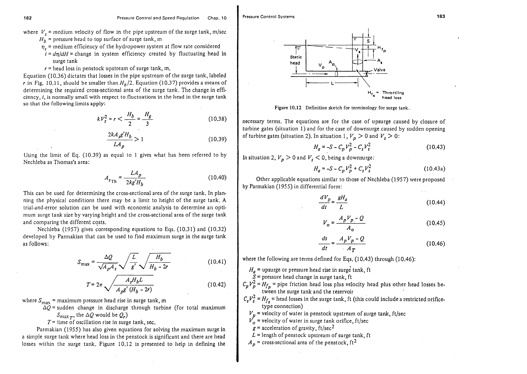
Parnlakian (1955) has also given equations for solving the maximum surge in
a shnple surge tank where head loss in the penstock is significant and there are head
losses within the surge tank. Figure 10.12 is presented to
help in defining the
Pressure
Control
Systems
f~
Static
-. -.
head
-
A,
Valve
--
-
H,,
=
Throttling
head
loss
Figure
10.12
Definition sketch for terminology for surge tank.
necessary
terms. The equations are for the case of upsurge caused by closure of
turbine gates (situation 1) and for the case of downsurge caused by sudden opening
of turbine gates (situation
2).
In situation 1,
Vp
>
0 and
V,
>
0:
H~
=
-s-
Cpv:
-
C,V:
In situation
2,
Vp
>
0 and
V,
<
0, being a downsurge:
Ha
=
-S-
CPv;
+
C,V:
(10.43a)
Other applicable equations similar to those of Nechleba (1957) were proposed
by Parniakian (1
955) in differential form:
'
where the following are terms defined for Eqs. (10.43) through (10.46):
H,
=
upsurge or pressure head rise in surge' tank, ft
S
=
pressure head change in surge tank, ft
C~V~
=
Hfp
=
pipe friction head loss plus velocity head plus other head losses be-
tween the surge tank and the reservoir
C,V:
=
Hfs
=
head losses in the surge tank, ft (this could include a restricted orifice-
type connection)
Vp
=
velocity of water in penstock upstream of surge tank, ft/sec
V,
=velocity of water in surge tank orifice, ft/sec
g
=
acceleration of gravity, ft/sec2
L
=
length of penstock upstream of surge tank, ft
Ap
=
cross-sectional area of the penstock, ft2
184
Pressure Control and Speed Regulation Chap.
10
A,
=
cross-sectional area of surge tank orifice, ft2
AT
=
cross-sectional area of surge tank, ft2
Q
=
discharge initially flowing in penstock, ft3/sec
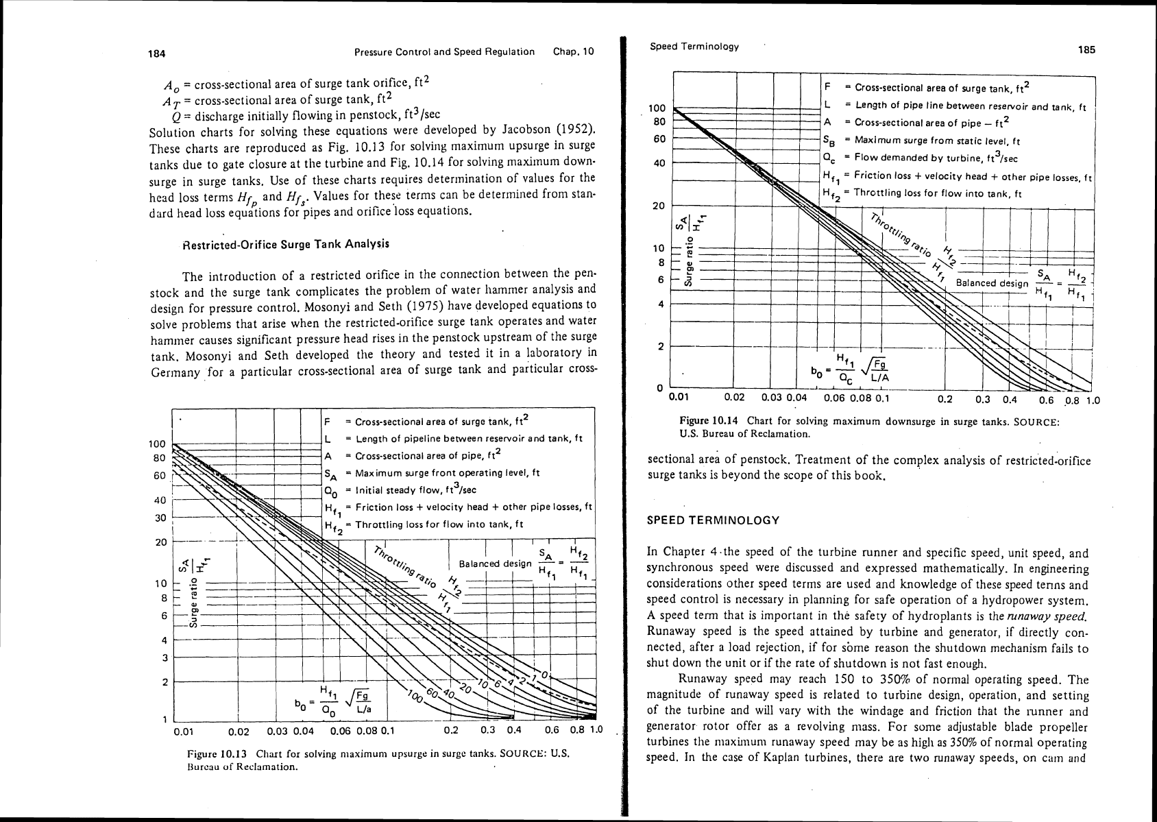
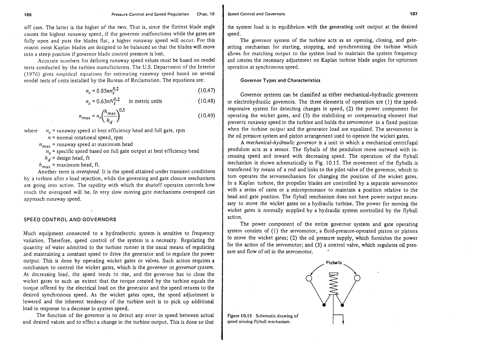
Solution charts for solving these equations were developed by Jacobson (1952).
These charts are reproduced as Fig. 10.13 for
solvir~g maximum upsurge in surge
tanks due to gate closure at
the turbine and Fig. 10.14 for solving maximum down-
surge in surge tanks. Use of these charts requires determination of values for the
head loss terms
HI
and
Hf3.
Values for these terms can be
determined
from stan-
p.
dard head loss equat~ons for pipes and orifice'loss equations.
Restricted-Orifice Surge
Tank
Analysis
The introduction of a restricted orifice in the connection between the pen-
stock and the surge tank complicates the problem of water
hammer analysis and
design for pressure control. Mosonyi and
Seth (1975) have developed equations to
solve problems that arise when the restricted-orifice surge tank operates and water
hammer causes significant pressure head rises in the penstock upstream of the surge
tank. Mosonyi and Seth developed the theory and tested it in a laboratory in
Germany for a particular cross-sectional area of surge tank and pa;ticular cross-
1
(
)
IF
=
Cross-sectional area of surgo tank, ft2
I
100
L
=
Length of pipeline between reservoir and tank, ft
80
A
=
Cross-sectional area of pipe, ft2
60
40
30
20
10
8
6
4
3
2
1
0.01 0.02 0.03 0.04 0.06 0.08 0.1 0.2 0.3 0.4 0.6 0.8 1.0
Figure
10.13 Cliart for solving niaximunl upsurge in surge tanks.
SOURCE:
U.S.
Ijurcau
of
Reclnmntion.
Speed Terminology
185
I
1
F
=
cross-sectional area of surge tank, ft2
Figure 10.14 Chart
for
solving maximum downsurge in surge tanks.
SOURCE:
U.S.
Bureau of Reclamation.
sectional area of penstock. Treatment of the complex analysis of restric'ted:orifice
surge tanks is beyond the scope of this book.
SPEED TERMINOLOGY
In Chapter 4.the speed of the turbine runner and specific speed, unit speed, and
synchronous speed were discussed
and
expressed mathematically. In engineering
considerations other speed terms are used and knowledge of these speed tenns and
speed control is necessary in planning for safe operation of a hydropower system.
A
speed term that
is
important in the safety
of
hydroplants is therunaway
speed.
Runaway speed is the speed attained by turbine and generator, if directly con-
nected, after a load rejection, if for sbme reason the shutdown mechanism fails to
shut down the unit or if the rate
of
shutdown is not fast enough.
Runaway speed may reach 150 to 35070 of normal operating speed. The
magnitude of runaway speed is related to turbine design, operation, and setting
of the turbine and will vary with the windage and friction that the
iunner and
generator rotor offer as a revolving
mass. For some adjustable blade propeller
turbines
the maximum runaway speed may be as high as
350%
of normal operating
speed. In the case of Kaplan turbines, there are two runaway speeds, on
cam and
186
Pressure Control and Speed Regulation Chap.
10
Speed Control and Governors
187
off cam. The latter is the higher of the two. That is, since the flattest blade angle
causes the highest runaway speed, if the governor
~iialfunctions wliile the gates are
fully open and puts the blades flat, a
higher runaway speed will occur. For this
rcasor, most Kaplan blades are designed to be balanced so that the blades will move
into a steep position if governor blade control pressure is lost.
Accurate
numbers for defining runaway speed values must be based on model
tests conducted by the turbine manufacturers. The
U.S.
Department of the Interior
(1976)
gives empirical equations for esti~nating runaway speed based on several
model tests of units installed by tlie Bureau of Reclamation. The equations are:
n,
=
0.85nnf.~
(10.47)
n,
=
0.63ne2
in rnetric units
where
11,
=
runaway speed at best efficiency head and full gate, rpin
n
=
nonnal rotational speed, rpm
rim,,
=
runaway speed at ~nauimum head
11,
=
specific speed based on full gate output at best efficiency head
hd
=
design head, ft
h,,
=
maximum head, ft.
Another term is
overspeed.
It is the speed attained under transient conditions
by a turbine after
;l
load rejection, while tlie governing and gate closure mechanisms
are going into action. The rapidity with which the shutoff operates controls how
much the
overspced will be. In very slow moving gate mechanisms overspeed can
approach runaway speed.
SPEED
CONTROL
AND
GOVERNORS
Much equipment connected to a hydroelectric system is sensitive to frequency
variation. Therefore, speed control of the system is a necessity. Regulating the
quantity of water admitted to the turbine runner is the usual means of regulating
and maintaining a constant speed to drive the generator and to regulate the power
output. This is done by operating wicket
gates or valves. Such action requires a
mechanism to control the wicket gates,
wluch is the
govertzor
or
govertlor system.
At decreasing load, the speed tends to rise, and tlie governor has to close the
wicket gates to such an extent that the torque created by the turbine equals the
torque offered by the electrical load on the generator and the speed returns to the
desired synchronous speed. As the wicket gates open, the speed adjustment is
lowered and the inherent tendency of the turbine unit is to pick up additional
load in response to a decrease in system speed.
The function of the governor is to detect any error in speed between actual
and desired values and to effect a change in the turbine output. This is done so
that
the system load is in equilibrium with the generating unit output at the desired
speed.
The governor system of the turbine acts as an opening, closing, and
gate-
setting mechanism for starting, stopping, and synchronizing the turbine which
allows for matching output to the system load to maintain the system frequency
and creates the necessary adjustment on Kaplan turbine blade angles for optimum
operation at synchronous speed.
Governor Types and Characteristics
Governor systems can be classified as either mechanical-hydraulic governors
or electrohydraulic governors. The three elements of operation are (1) the
speed-
responsive system for detecting changes in speed,
(2)
the power component for
operating the wicket gates, and
(3)
the stabilizing or compensating element that
prevents runaway speed in the turbine and holds the
servomotor
in a ftved position
when the turbine output and the generator load are equalized. The servomotor is
the oil pressure system and piston arrangement used to operate the wicket gates.
A
mechanical-hydraulic governor
is a unit in which a mechanical centrifugal
pendulum acts as a sensor. The
flyballs of the pendulum move outward with in-
creasing speed and inward with decreasing speed. The operation of the
flyball
mechanism is shown schematically in Fig.
10.15.
The movement of the flyballs is
transferred by means of a rod and links to the pilot valve of the governor, which
in
turn operates the servomechanism for changing the position of the wicket gates.
In a Kaplan turbine, the propeller blades are controlled by a separate servomotor
with a series of cams or a microprocessor to maintain a position relative to the
head and gate position. The
flyball mechanism does not have power output neces-
sary to move the wicket gates on a hydraulic turbine. The power for moving the
wicket gates is normally supplied by a hydraulic system controlled by the
flyball
action.
The power component of the entire governor system and gate operating
system consists of
(1)
the servomotor, a fluid-pressure-operated piston or pistons
to move the wicket gates;
(2)
the oil pressure supply, which furnishes the power
for the action of the servomotor; and
(3)
a control valve, which regulates oil pres-
sure and flow of oil in the servomotor.
Figure
10.15
Schematic drawing of
speed sensing
flyball
mechanism.
h