Warnick C.C. Hydropower engineering
Подождите немного. Документ загружается.

128
Water Passages Chap.
8
where
Dp
=
penstock diameter, In
Q
=
water flow, m3/sec.
Sarkaria (1 979) developed an empirical approach for determining steel
pcn-
stock diameter by using data from large hydro projects with heads varying from
187 ft (57
m) to 1025 ft
(313
~n) and power capacities ranging from 206,000 hp
(154
MW)
to
978,000
hp
(730
MW).
He reported that the economical diameter of
the penstock is given by the equation
where
D
=
economical penstock diameter, ft
p
=
rated turbine capacity, hp
h
=
rated net head, ft
The study verified his earlier study reported in 1958. The two empirical studies
g~ving Eqs.
(8.8)
and (8.9) were for periods before present energy crunch conditions
and did
not take into account penstock length or the cost of lost power in penstock
flow. Therefore, the equations should be used with caution.
The
U.S.
Department of the Interior (1967) gives a very sophisticated graphi-
cal and
empirical
approach to determining the economical diameter of steel pen-
stocks
wh~cll ~ncludes the following variables:
Cost of pipe per pound, installed, in dollars
Value of
powzr lost, in dollars per kwh
Plant efficiency
Pipe joint efficiency
Weighted average head, including water hammer effect, in feet (based on
design head)
Friction coefficient in Scobey formula (0.34)
Ratio of overweight to weight of pipe shell
Flow at design head, in
ft3/sec
Allowable hoop tension.stress, in lb/in2
Weighted average plate thickness, in inches
This approach is presented in a series of graphs, with a step-by-step example.
Penstocks that are not encased in
the concrete of a dam or buried in earth
and rock require support. Details on the engineering analysis of the forces acting on
and the
structurd design of support piers and anchors are available from the
U.S.
Department of the Interior (1967). An excellent reference on structural design
temperature problems and construction requirements of penstocks is a paper by
Eberhsrdt
(1 975).
A
rule
of
tllumb used by some engineers in penstock design and
selection
1s
that the Ina?cirnuln water velocity should not exceed 35 ft/sec.
Spiral Cases and Distributor Assemblies
SPIRAL CASES AND DISTRIBUTOR ASSEMBLIES
Distributor assemblies consisting
of
spiral cases, head cover, bottorn ring, and wicket
gates are used to control the amount and direction of the water entering into the
rotating turbine. For low heads, below
20
ft
(6.1
m) an open-flume or pressure
case setting may he used. These are simply rectangular or cylindrical chambers.
Register and cylindrical gates were used in early hydropower installations: they
were basically a cylinder with rectangular openings that could be
moved circum-
ferentially to block or permit the flow into the turbine or a cylinder that was
moved axially to permit flow. Normally, now to obtain better part load efficiency,
wicket gates control flow into the turbine within the open flume or within the
pressure case.
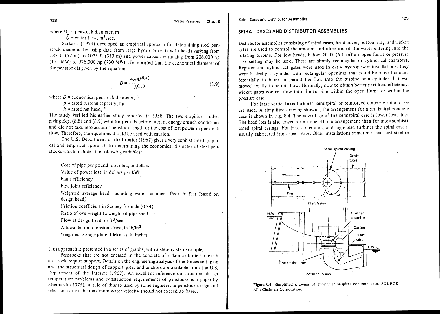
For large vertical-axis turbines, semispiral or reinforced concrete spiral cases
are used.
A
simplified drawing showing the arrangement for a semispiral concrete
case is shown in Fig. 8.4. The advantage of the semispiral case is lower head loss.
The
head loss is also lower for an open-flume arrangement than for Inore sophisti-
cated spiral casings. For large-, medium-, and high-head turbines the spiral case is
usually fabricated from steel plate. Older installations sometimes had cast steei or
Semi-spiral casing
/
Draft
I
I
Plan View
Sectional
View
Figure
8.4
Si~l~plificd drawing of typical scrni-spiral concrete
casc.
SOURCE:
Allis-Chulnlers Corporation.
Water Passages Chap.
8
Spiral casing Draft
Plan View
'I
I
Sectional View
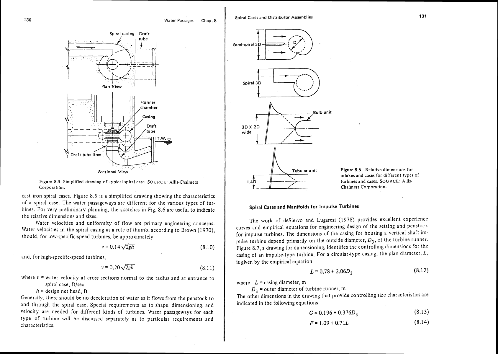
Figure
8.5
Simplificd drawing of typical spiral case.
SOURCE:
Allis-Chalmers
Corporation.
cast iron spiral cases. Figure
8.5
is a simplified drawing showing the characteristics
of a spiral case. The water passageways are different for the various types of
tur-
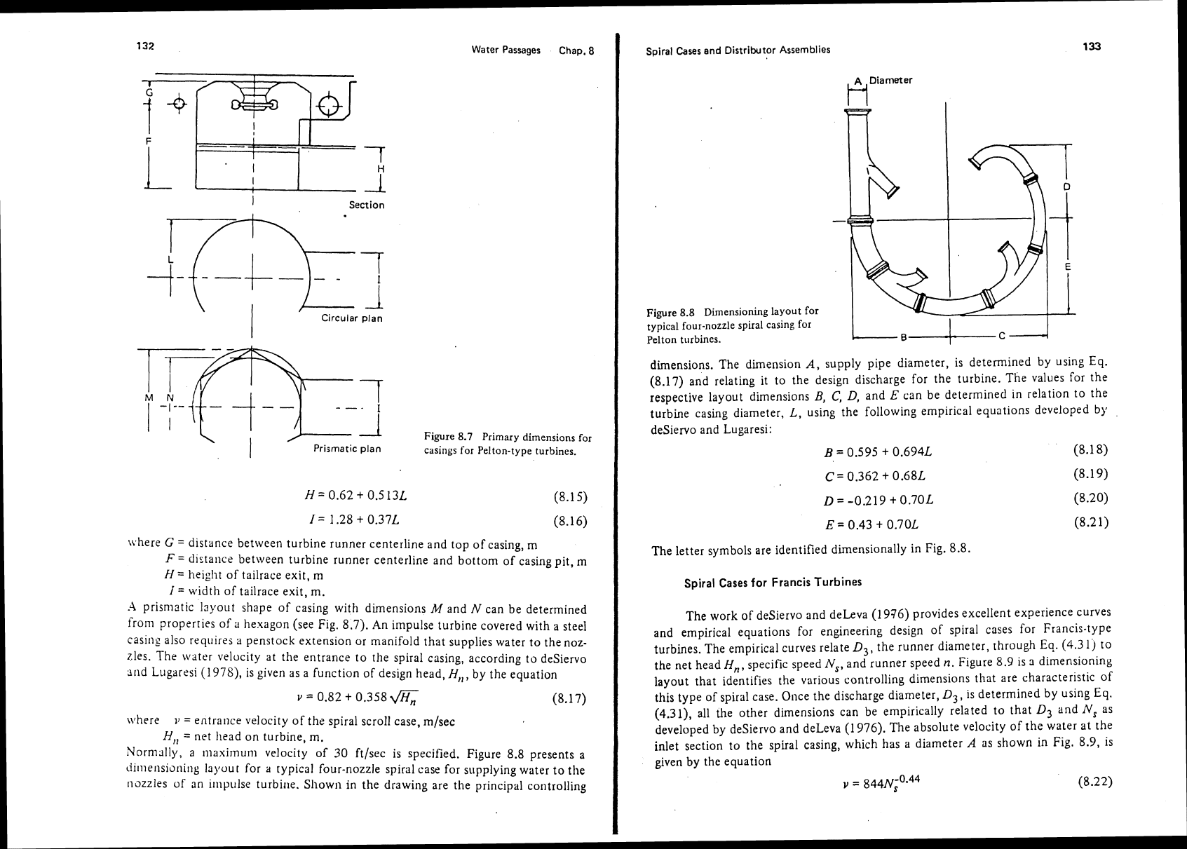
Lines. For very preliminary planning, the sketches in Fig. 8.6 are useful to indicate
the relative d~mensions and sizes.
Water velocities and
uniforn~ity of flow are primary engineering concerns.
Water velocities in the spiral casing as a rule of
thulnb, according to Brown
(1970),
should, for low-specific-speed
turbines,
be approximately
=
0.14m (8.10)
and, for high-specific-speed turbines,
=
0.20
rn
where
v
=
water velocity at cross sections normal to the radius and at entrance to
spiral case,
ft/sec
I;
=
design net head, ft
Generally, there should be no deceleration of water as it flows from the penstock to
and through the spiral case. Special requirements as to shape, dimensioning, and
velocity are needed for different kinds of turbines. Water passageways for each
type of turbine will be discussed separately as to particular requirements and
characteristics.
Soiral Cases and Distributor Assemblies
-
---.
Semi-spiral 3D
wide
Figure
8.6
Relative dimensions for
intakes and cases for different types of
1.4
turbines and cases.
SOURCE:
Allis-
k-
Chalmers Corporation.
Spiral Cases
and Manifolds for
Impulse Turbines
The work of deSiervo and Lugaresi
(1978)
provides excellen: experience
curves and empirical equations for engineering design of the setting and penstock
for impulse turbines. The dimensions of the casing for housing a vertical shaft
irn-
pulse turbine depend primarily on the outside diameter,
D3,
of the turbine runner.
Figure
8.7,
a drawing for dimensioning, identifies the controlling dimensions for
the
casing of an impulse-type turbine. For a circular-type casing, the plan diameter,
L,
is given by the empirical equation
L
=
0.78
+
2.06D3
(8.1
2)
where
L
=
casing diameter, m
D3
=
outer diameter of turbine runner, rn
The other dimensions in the drawing that provide controlling size characteristics are
indicated in
the following equations:
C
=
0.196
+
0.37603
(8.1
3)
F=
1.09
t
0.711,
(8.14)
Water Passages Chap.
8
I
Section
Circular plan
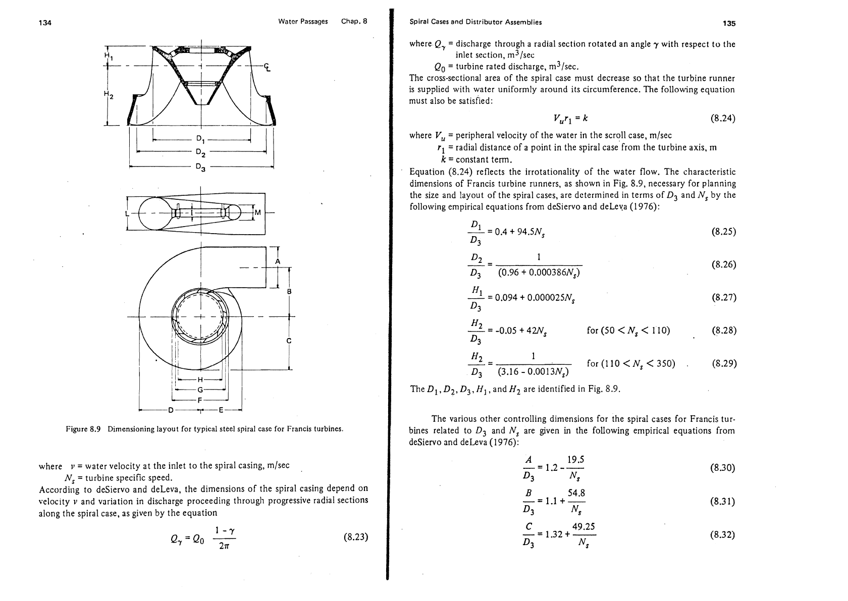
Figure
8.7
Primary dimensions for
Prismatic plan
casings for Pelton-type turbines.
where
G
=
distance between turbine runner centerline and top of casing, m
F
=
distance between turbine runner centerline and bottom of casing pit,
rn
H
=
height of tailrace exit, m
I
=
width of tailrace exit, m.
.4
prismatic Isyout shape of casing with dimensions
M
and
N
can be determined
from properties of
a
hexagon (see Fig.
8.7).
An impulse turbine covered with a steel
casing also
requires a penstock extension or manifold that supplies water
to
the noz-
zles. The
\\later velocity at the entrance to the spiral casing, according to deSiervo
31ld Lugaresi (1978), is given as a function of design head,
H,,,
by the equation
\\.here
11
=
entrance velocity of the spiral scroll case, m/sec
H,,
=
net head on turbine, m.
Norn~slly, a maxirnum velocity of 30 ftlsec is specified. Figure 8.8 presents a
iiilnensioni~lg layour for
a
typical four-nozzle spiral case for supplying water to the
nozzles of an
iinpulse turbine. Shown in the drawing are the principal controlling
Spiral Cases and Distributor Assemblies
Fiyre
8.8
Dimensioning layout for
typical four-nozzle spiral casing for
-.
pelton turbines.
dimensions. The dimension
A,
supply pipe diameter, is determined by using Eq.
(8.17) and relating it to the design discharge for the turbine. The values for the
respective layout dimensions
B,
C,
D,
and
E
can be determined in relation to the
turbine casing diameter,
L,
using the following empirical equations developed
by
desiervo and Lugaresi:
B
=
0.595
+
0.694L
(8.1
8)
The letter symbols are identified dimensionally in Fig.
8.8.
Spiral Cases for Francis Turbines
The work of deSiervo and deLeva (1 976) provides excellent experience curves
and empirical equations for engineering design of spiral cases for Francis-type
turbines. The empirical curves relate
D3,
the runner diameter, through
Eq.
(4.3
1)
to
the net head
H,, specific speed
N,,
and runner speed
n.
Figure
8.9
is
3
dimension~ng
layout that identifies the various controlling dimensions that are
characteristic
of
this type of spiral case.
Once the discharge diameter,
D3,
is determined by using Eq.
(4.31), all the other dimensions can be empirically related to that
D3
and
N,
as
developed by
deSiervo and deLeva
(1
976). The absolute velocity of the water at the
inlet section to the spiral casing, which has a diameter
A
as shown
in
Fig. 8.9, is
given
by
the equation
v
=
s
(8.22)
Water Passages Chap.
8
Figure
8.9
Dimensioning layout for typical steel spiral case for Francis turbines.
where
11
=
water velocity at the inlet to the spiral casing, m/sec
Ns
=
turbine specific speed.
According to
deSiervo and deleva, the dimensions of the spiral casing depend on
velocity
11
and variation in discharge proceeding through progressive radial sections
along the spiral case, as given by the equation
Spiral
Cases
and
Distributor Assemblies
135
where.Q,
=
discharge through a radial section rotated an angle
-y
with respect to the
inlet section,
m3/sec
Qo
=
turbine rated discharge, m3/sec.
The cross-sectional area of the spiral case must decrease so that the turbine runner
is supplied with water uniformly around its circumference. The following equation
must also be satisfied:
Vurl
=
k
(8.24)
where
V,
=
peripheral velocity of the water in the scroll case, m/sec
r1
=radial distance of a point in the spiral case'from the turbine axis,
rn
k
=
constant term.
Equation (8.24) reflects the irrotationality of the water flow. The characteristic
dimensions of Francis turbine runners, as shown in Fig. 8.9, necessary for planning
the size and layout of the spiral cases, are determined in terms of
D3 and
1VS
by the
following empirical equations from
deSiervo and deLeya (1 976):
The
Dl, D2,
D3,
HI,
and
Hz
are identified in Fig. 8.9.
The various other controlling dimensions for the spiral cases for Francis tur-
bines related to
D3 and
Ns
are given in the following empirical equations from
deSiervo and deLeva (1976):
Water Passages Chap.
8
The various letter syn~bols are identified in Fig.
8.9.
The
U.S.
Department of the Interior (1976) also gives graphs and interpretive
dimensional drawings for detennining the characteristic size and shape of steel
spiral cases for reaction-type turbines. Standardized dimensioning procedures are
also presented in
Allis-Chalmers Corporation's
Pllblicatiotl
54X10084-01
(n.d.).
This publication has excellent detailed drawings that are especially labeled to sllow
how
the spiral case is connected to the stay ring and positioned with respect to the
wicket gates.
Spiral Cases
for
Kaplan Turbines
Further work of
deSiervo and deLeva (1978) provides excellent experience
curves and
empirical equations for engineering design of semispiral cases and spiral
cases for Kaplan turbines. The various controlling dimensions are related to the dis-
charge
diameter
DAf
and its relation with net head
H,,
specific speed
N,,
and
runner speed
11.
The value of
Dnf
is obtained by applying Eq.
(4.34).
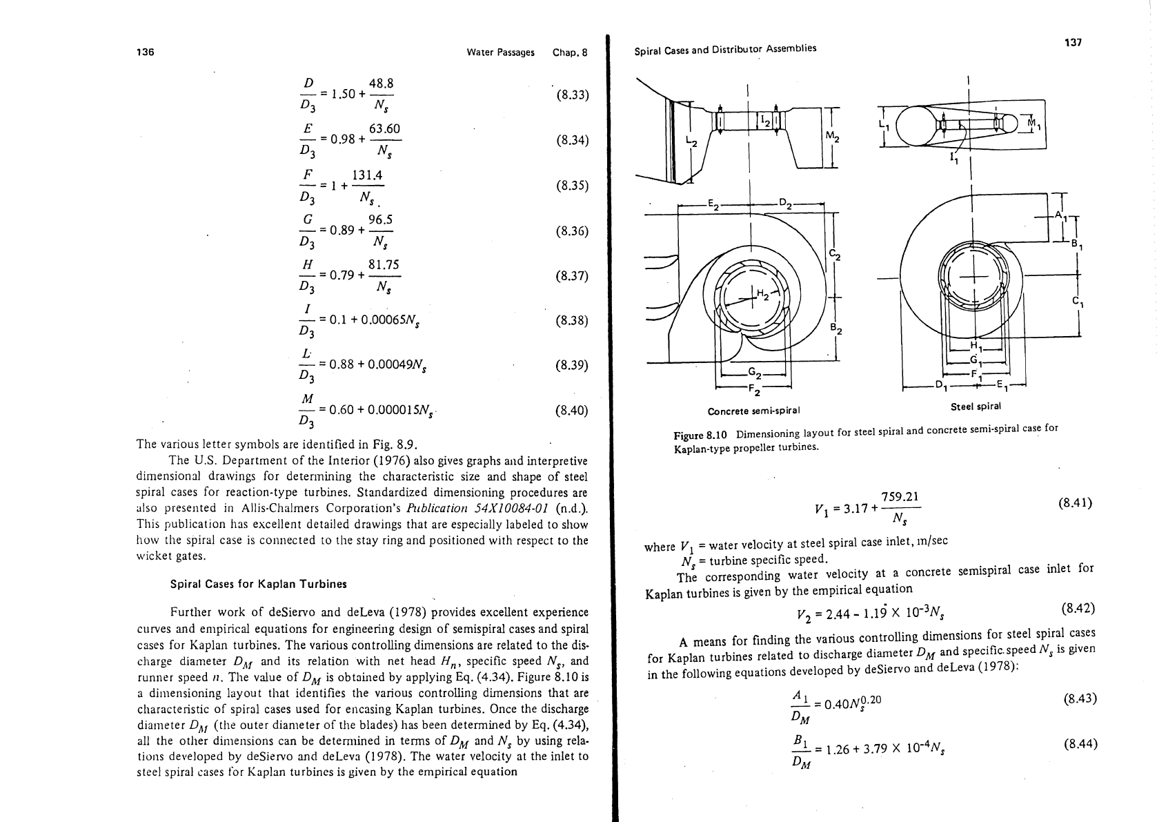
Figure
8.10
is
a dimensioning layout
that identifies the various controlling dimensions that are
cllaracteristic of spiral cases used for encasing Kaplan turbines. Once the discharge
diameter
DAl
(the outer diameter of the blades) has been determined by Eq. (4.34),
all the other dimensions can be determined in terms of
DM
and
Ns
by using rela-
tions developed by
deSiewo
and
deLeva (1978). The water velocity at the inlet to
steel spiral cases for Kaplan turbines is given by the empirical equation
Spiral
Cases
and
Distributor Assemblies
Concrete
semi-spiral
Steel
spiral
Figure 8-10
Dimensioning
layout for steel spiral and ConCrete semi-spiral case for
Kaplan-type propeller turbines.
where
V,
=
water velocity at steel spiral case inlet, inlsec
Ns
=
turbine specific speed.
The corresponding water velocity at a concrete semispiral case inlet for
Kaplan turbines is given by the empirical equation
V,
=
2.44
-
1.19'
X
~o-~N,
A
means for finding the various controlling dimensions for steel spiral cases
for Kaplan turbines related to discharge diameter
DM
and specific.speed
N,
is given
in the following equations developed by
desiewo and deLeva (1978):
Spiral
Cases
and
Distributor
Assemblies
139
Water Passages
Chap.
8
The letter symbols are identified in Fig. 8.10; all linear terms are expressed in
meters and
NJ
is the metric form of specific speed. Comparison of these equations
shows that for the same-size turbines the width of the spiral case is less for the con-
crete semispiral case than for the steel spiral case, mainly because of cross-sectional
shape of the spiral
rorm.
The
U.S.
Department of the Interior (1976) also provides graphs and typical
proportional labeled drawings for designing concrete semispiral cases.
Engineering
Monograph No.
20
indicates that the following basic criteria should govern design
of semispiral cases:
1. The velocity
(V2)
at entrance to the semispiral case, just upstream from the
stay-vane
f3undation cone, should be 14% of spouting velocity at design
head, but in no case should
V2
be less than 5 ft/sec (1.5 m/sec).
Identification of the respective dimensions is indicated in Fig. 8.10 with all terms in
meters;
N,
is the metric foml of specific speed.
Controlling dimensions for concrete semispiral cases for Kaplan turbines
related to
Dnf
and
N,
can be found by using the following empirical equations
from the work of
deSiervo and deLeva (1978):
2.
Water passage sections should approach a square to minimize friction loss.
The height of the entrance section should be approximately one-third the
width of the intake. All interior corners should have 12-in. (0.3-m) fillets to
minimize eddies.
3.
The baffle vane should be in the downstream quadrant approximately
45'
from the transverse centerline. To induce equal distribution of flow in the
entrance, the turbine centerline is offset from the centerline of the intake
passage. This offset will place one-third of the stay ring intake opening in
one-third of the area of the entrance. The remaining two-thirds of the flow
enten the stay ring directly and through the large semispiral passage.
4.
The large semispiral is designed for uniform angular velocity
(V2)
of flow
around the spiral.
V,
=q/a
and is a constant in which
q
is diminished in
proportion to the remaining stay-ring arc and
a
is the radial cross-sectional
area.
5.
The entrance wall upstream from the large semispiral section should lie in
the same vertical plane with the corresponding sidewalk of the draft tube for
structural economy.
140
Water
Passages
Chap.
8
6.
The intake is laid as a simple rectangular intake without intermediate piers,
with a
0.7
coefficient of contraction from intake opening to casing entrance.
The change of area is similar to that
found in a jet issuing from an orifice.
The intake opening should have a rninimutn depth of water above it equiva-
lent
to
0.3
the height of the opening, to avoid entraining air and to assure
uniform vertical distribution of flow in the entrance section of the case.
Special structural problems with the civil works of the installation may
dictate piers in the transition approaching' the spiral case. Cautions for this and
representative details for preparing the design are available from the
U.S.
Depart-
menr of the Interior (1976).
DRAFT
TUBES
Draft tubes are the final components of the water passages of hydropower plants
and are necessary in carrying the water away from the turbine runner to the tail-
race, where the
water rejoins the stream channel or receiving body of water. The
proper engineering design of draft tubes provides for the recovery of a portion of
the velocity head as it leaves the turbine proper to recover energy and improve the
efficiency of the turbine unit. The draft tube also permits utilization of the runner
discharge head if the runner is set above the tailwater level. The discussion in
Chapter
7
e~nphasized the importance of limiting the setting of the runner with
respect to the tailwater.
Draft tubes usually consist of steel sections which change shape from circular
t~ rectangular
in
cross section. The sections expand in cross-sectional area to
decrease the water velocity
with a minimum occurrence of vortexes and maintain
a nearly uniform velocity at any section. The draft tube is usually formed in rein-
forced concrete. The principal engineering problems are
determining the water
velocity at the exit to the draft tube and
detetrnining the controlling dimensions of
the draft tube.
Manufacturers consider the draft tube as a part of the turbine when determin-
ing an efficiency guarantee. Therefore, it is customary for the manufacturer to
furnish the final dimensions for draft tube shape as limited within certain civil
\vorks restraints of the structural components of a hydropower plant.
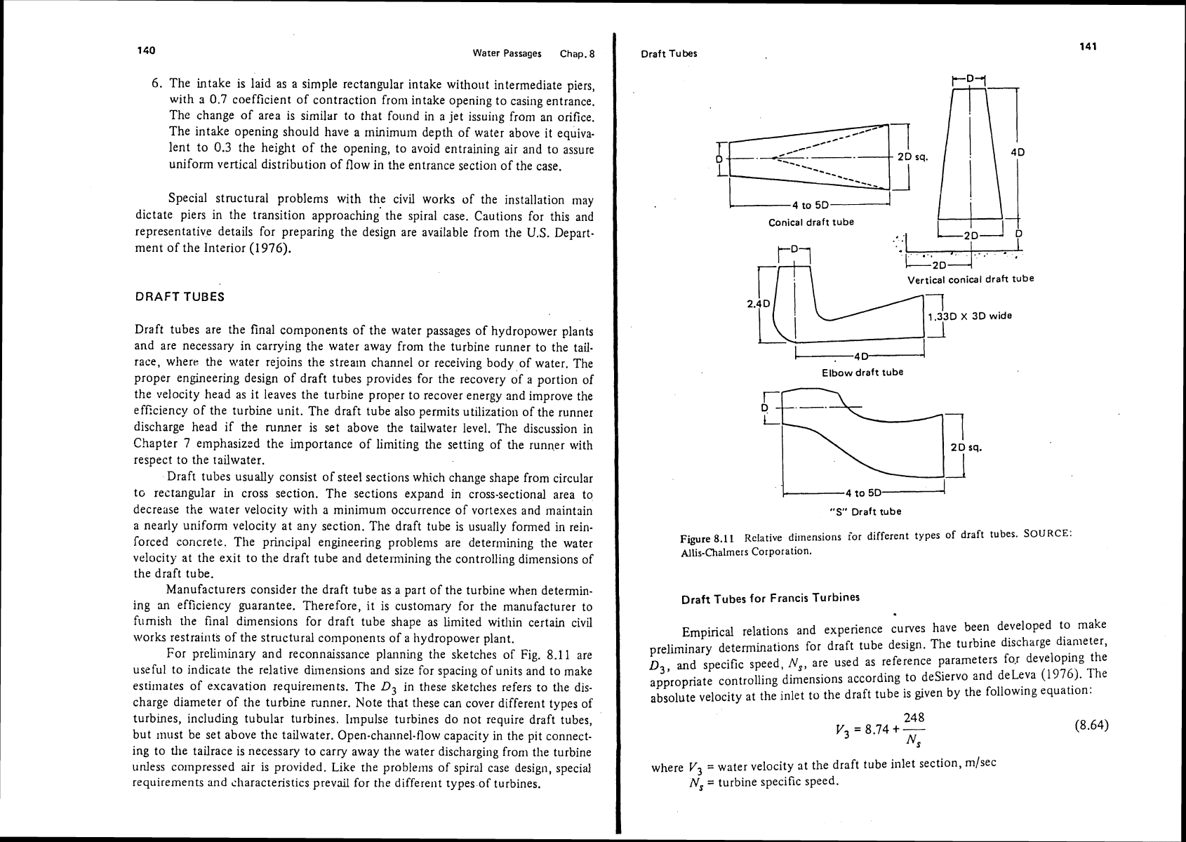
For
preliminsry and reconnaissance planning the sketches of Fig.
8.11
are
useful to
indicatz the relative dimensions and size for spacing of units and to make
estimates of excavation requirements. The
Dj
in these sketches refers to the dis-
charge diameter of the turbine
rdnner. Note that these can cover different types of
turbines, including tubular turbines.
Impulse turbines do not require draft tubes,
but
must be set above the tailwater. Open-channel-flow capacity in the pit connect-
ing to
the tailrace is necessary to carry away the water discharging from the turbine
unless
co~npressed air is provided. Like the problems of spiral case design, special
requirements and
sharacteristics prevail for the different types of turbines.
Draft Tubes
L
4
to
5
D
-------I
Conical
draft
tube
:
:I
Elbow draft tube
"9'
Draft tube
Figure
8.11
Relative
di~nensions for different types of draft tubes.
SOURCE:
Allis-Chalmers Corporation.
Draft
Tubes
for
Francis Turbines
Empirical relations and experience curves have been developed to make
preliminary determinations for draft tube design. The turbine discharge diameter,
D3,
and specific speed,
N,,
are used as reference parameters fo~ developing the
appropriate controlling dimensions according to
deSiervo and deLeva
(1976).
The
absolute velocity at the inlet to the draft tube is given by the following equation:
where
V3
=
water velocity at the draft tube inlet section, rnlsec
Ns
=
turbine specific speed.
Draft
Tubes
143
Water
Passages
Chap.
8
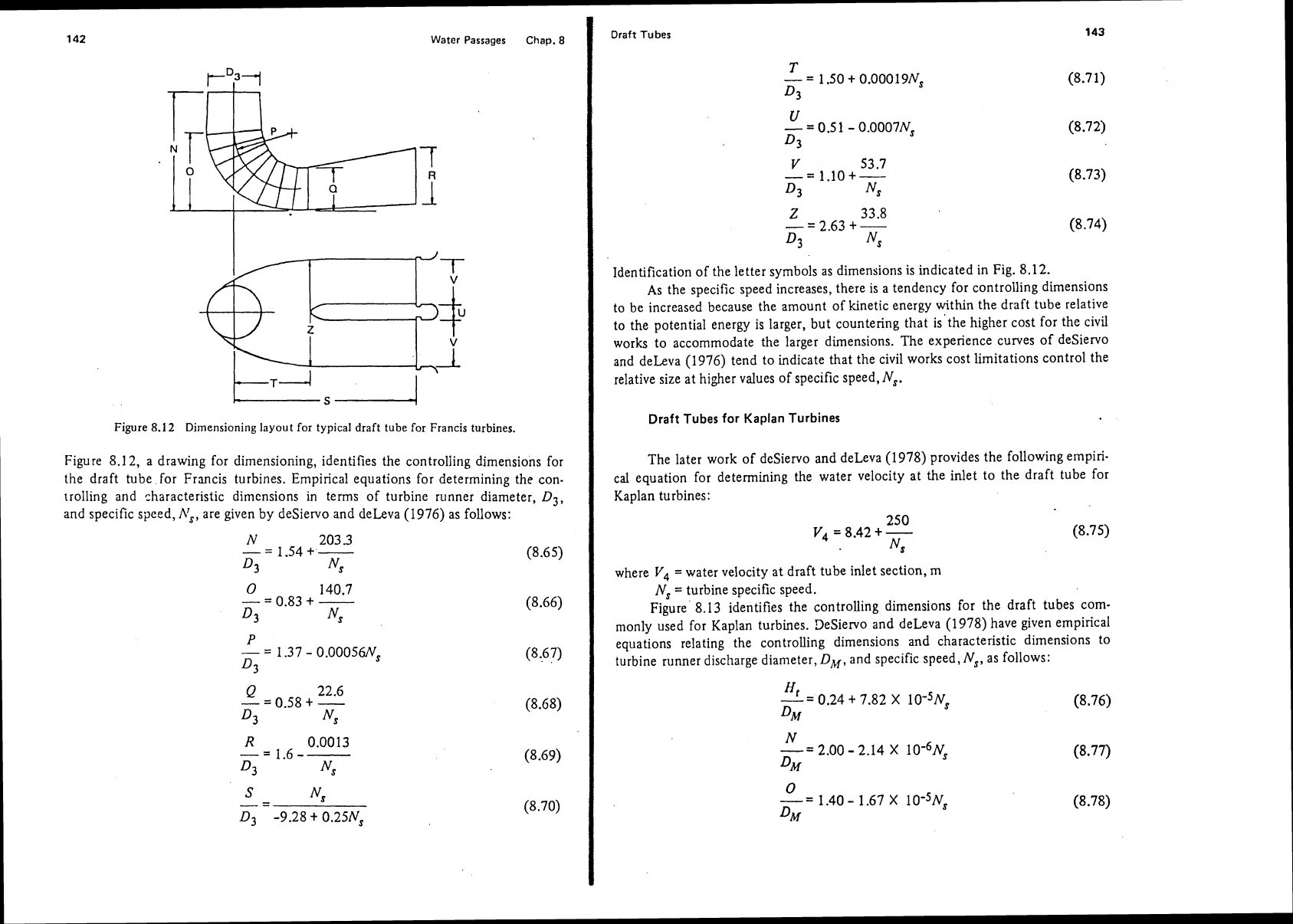
Identification of the letter symbols as dimensions is indicated in Fig. 8.12.
As the specific speed increases, there is a tendency for controlling dimensions
to be increased because the amount of kinetic energy within the draft tube relative
to the potential energy is larger, but countering that is'the higher cost for the civil
works to accommodate the larger dimensions. The experience curves of
desiervo
and deLeva (1976) tend to indicate that the civil works cost limitations control the
relative size at higher values of specific speed,
Ns.
Draft
Tubes
for Kaplan Turbines
Figure
8.12
Dirnensioning layout for typical draft tube for Francis turbines.
The later work of deSiervo and deLeva (1978) provides the following empiri-
cal
equation for determining the water velocity
at
the inlet to the draft tube for
Kaplan turbines:
Figure 8.1
2,
a drawing for dimensioning, identifies the controlling dimensions for
the draft tube for Francis turbines. Empirical equations for determining the con-
trolling and characteristic dimensions in terms of turbine runner diameter,
D3,
and specific speed,
A:,
are given by deSiervo and deLeva (1976) as follows:
where
V4
=
water velocity at draft tube inlet section, m
Ns
=
turbine specific speed.
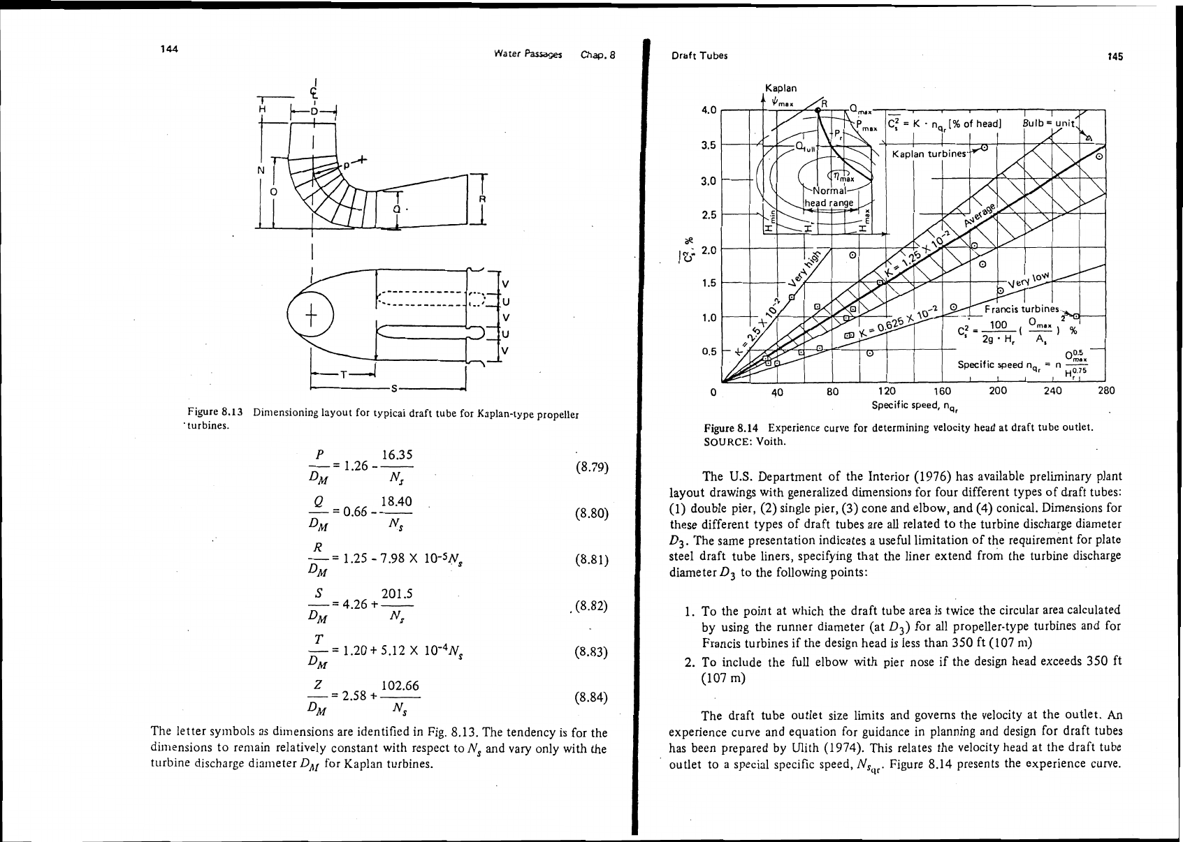
Figure 8.13 identifies the controlling dimensions for the draft tubes com-
monly used for Kaplan turbines.
DeSiervo and deLeva (1978) have given empirical
equations relating the controlling dimensions and characteristic dimensions to
turbine runner discharge diameter,
DM,
and specific speed,
Ns,
as follows:
Water
~=GW
Chap.
8
Figure
8.13
Dimensioning layout for typicai draft tube
for
Kaplan-type propeller
'turbines.
The letter symbols as dimensions are identified in Fig. 8.13. The tendency is for the
dimensions to remain relatively constant with respect to
N,
and vary only with the
turbine discharge diameter
DJI
for Kaplsn turbines.
I
Draft
Tubes
145
Specific
speed,
nq,
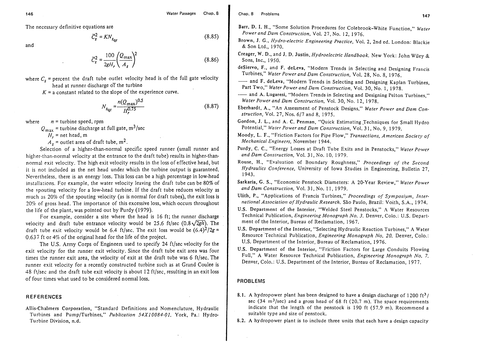
Figure
8.14
Experience curve for determining velocity head
at
draft tube outlet.
SOURCE:
Voith.
The
U.S.
Department of the Interior (1976) has available preliminary plant
layout drawings with generalized dimensions for four different types of draft tubes:
(1)
double pier, (2) single pier,
(3)
cone and elbow, and (4) conical. Dimensions for
these different types of draft tubes are all related to the turbine discharge diameter
D3.
The same presentation indicates a useful limitation of the requirement for plate
steel draft tube liners, specifying that the liner extend
from the turbine discharge
diameter
Dg
to the following points:
1.
To the point at which the draft tube area is twice the circular area calculated
by using the runner diameter (at
D3) for all propeller-type turbines and for
Francis turbines if the design head is less
than
350 ft
(107
n~)
2.
To include the full elbow with pier nose if the design head exceeds
350
ft
(107 m)
The draft tube outlet size limits and governs the velocity at the outlet.
An
experience curve and equation for guidance in planning and design for draft tubes
has been prepared by Ulith (1974). This relates the velocity head at the draft tube
outlet to a special specific speed,
NSgr.
Figure 8.14 presents the experience curve.
146
Water Passages Chap.
8
The necessary definitive equations are
C:
=
KN,,.
and
where
C,
=
percent the draft tube outlet velocity head is of the full gate velocity
head at runner discharge
oT the turbine
K
=
a constant related to the slope of the experience curve.
where
n
=
turbine speed, rpm
Q,,
=
turbine discharge at full gate, m3/sec
H,
=
net head, m
A,
=
outlet area of draft tube,
m2.
Seiection of a higher-than-normal specific speed runner (small runner and
higher-than-normal velocity at the entrance to the draft tube) results in higher-than-
normal exit velocity. The high exit velocity results in the loss of effective head, but
it is riot included as the net head under which the turbine output is guaranteed.
Nevertheless. there is an energy loss. This loss can be a high percentage in low-head
installarions. For example, the water velocity leaving the draft tube can be
80%
of
the
spouti~~g velocity for a lo\v-]lead turbine. If the draft tube reduces velocity as
much
ns
20%
of the spouting velocity (as is normal for draft tubes), the exit loss is
20%
of gross head. The importance of this excessive loss, which occurs throughout
the life of the plant, was pointed out by Purdy (1979).
For example, consider a site where the head is 16 ft; the runner discharge
velocity and draft tube entrance velocity would be 25.6
ftlsec (0.8m). The
draft tube exit velocity would be 6.4
ftlsec. The exit loss would be (~.4)~/2~=
0.637 ft or 4% of the original head for the life of the project.
The
U.S.
Army Corps of Engineers used to specify 24 ft/sec velocity for the
exit velocity for the runner exit velocity. Since the draft tube exit area was four
times the runner exit area, the velocity of exit at the draft tube was
G
ft/sec. The
runner exit velocity for a recently constructed turbine such as at Grand Coulee is
48
f!/sec and the draft tube exit velocity is about 12 ftlsec, resulting in an exit loss
of four times what used to be considered nomial loss.
REFERENCES
Allis-Chalmers Corporation, "Standard
Definitions and Nomenclature, Hydraulic
Turbines and
Pu~np/Turbines,"
Publication
54x10084-01.
York, Pa.: Hydro-
Turbine Division, n.d.
Chap.
8
Problems
147
Barr, D. I.
H..
"Some Solution Procedures for Colebrook-White Function,"
Water
Power and Darn
Constrrrction,
Vol. 27, No. 12. 1976.
Brown,
J.
G.,
Hydro-electric Engineering Practice,
Vol. 2, 2nd ed. London: Blackie
&
Son Ltd., 1970.
Creager,
W.
D.,
and
J.
D.
Justin,
Hydroelectric Handbook.
New York: John Wile),
$
Sons, Inc., 1950.
desiervo,
F.,
and
F.
deleva, "Modern Trends in Selecting and Designing Fra~~cis
Turbines,"
Water Power and Darn Corlstruction,
Vol. 28, No. 8, 1976.
-
and
F.
deLeva, "Modern Trends in Selecting and Designing Kaplan Turbines,
Part Two,"
Water Power and Darn Construction,
Vol. 30, No. 1, 1978.
--
and A. Lugaresi, "Modem Trends in Selecting and Designing Pelton Turbines,"
Water Power and Dan1 Construction,
Vol. 30, No. 12, 1978.
Eberhardt,
A.,
"An Assessment of Penstock Designs,"
Water Power and Dam Con-
struction,
Vol. 27, Nos. 617 and 8, 1975.
Gordon,
J.
L., and
A.
C. Penman, "Quick Estimating Techniques for Small Hydro
Potential,"
lVarar
Power and Dar?l Cor~str~tction,
Vol. 3 1, No. 9, 1979.
Moody,
L.
F.,
"Friction Factors for Pipe Flow,"
Transactions, Amcricarl Society of
Mechanical
Bngirlecrs,
November 1944.
Purdy,
C.
C.,
"Energy Losses at Draft Tube Exits and in Penstocks,"
Water Power
and Dam Cor~struction,
Vol.
3
1, NO. 10, 1979.
Rouse,
H.,
"Evaluation of Boundary Roughness,"
Proceedings of the Srcorld
-.
Hydraulics Conjerence,
University of Iowa Studies in Engineering, Bulletin 27,
1943.
Sarkaria,
G.
S..
"Economic Penstock Diameters: A 20-Year Review,"
Water Power
arld Dan1 Construction,
Vol.
3
1, No.
1
1,
1979.
Ulith, P., "Applications of Francis Turbines,"
Proceedings of Symposium, Itlrer-
national
as so cia ti or^
of Hydraulic Research.
Sio Paulo, Brazil: Voith, S.A., 1974.
U.S. Department of the Interior, "Welded Steel Penstocks,"
A
Water Resources
Technical Publication,
Engineering hdonograph No.
3.
Denver, Colo.: U.S. Depart-
ment of the Interior, Bureau of Reclamation, 1967.
U.S. Department of the Interior, "Selecting Hydraulic Reaction Turbines," A Water
Resource Technical Publication,
Engineering Monograph No.
20.
Denver, Colo.:
U.S. Department of the Interior, Bureau of Reclamation, 1976.
U.S. Department of the Interior, "Friction Factors for Large Conduits Flowing
Full," A Water Resource Technical Publication,
Erlgineerirlg Monograph No.
7.
Denver, Colo.: U.S. Department of the Interior, Bureau of Reclamation, 1977.
PROBLEMS
8.1.
A
hydropower plant has been designed to have a design discharge of 1200 ft3/
sec (34 m3/sec) and a gross head of
68
ft (20.7 m). The space requirements
indicate that the length of the penstock is 190 ft (57.9 m). Recommend
a
suitable type and size of penstock.
8.2. A hydropower plant is to include three units that each have a design capacity