Warnick C.C. Hydropower engineering
Подождите немного. Документ загружается.

108
Cavitation
and
Turbine Setting Chap.
7
critical areas in the system do not permit excessive cavitation to occur. The setting
is dictated by
econonlics and may require placing the turbine well below the tail-
water, which can be very expensive due to excavation and collcrete costs. In some
cases it has been
economically
justifiable to permit some cavitation and use very
resistant metal and/or repair of the damage to compensate for
the pitting. Table 7.1
gives the weight loss of different
nietals for the same cavitation conditions as
re-
ported by the
U.S.
Army Corps
of
Engineers.
Frequently, a layer of cavitation-resistant material is overlaid by welding on
the base metal. The locations and size of the areas requiring such overlay are
dzterrnined after
model tests have been made and by experience. Nearly all turbines
do experience
some cavitation damage, so a control measure
is
to build up the darn-
a2cd surfaces with stainless steel welding rod or welded-on plates.
Sometimes special anticavitation fins have been added to Kaplan and propeller
turbine blades to minimize blade tip cavitation. According to Csanady
(1964),
Rasn~ussen in 195G reported that the addition of air bubbles produces an elastic
fluid that apparently cushions the action of the pressure pulses. Csanady indicates
that amounts of only 1 to
2
parts per thousand of air produce a significant reduc-
tion in damage. According to Csanady, Plesset (1960) found that a thin hydrogen
film on a
~netal surface could stop pitting.
Indirectly through design, the selection of the speed of the turbine can be
~lsed to control cavitation. Increasing the speed of the runner results in smaller
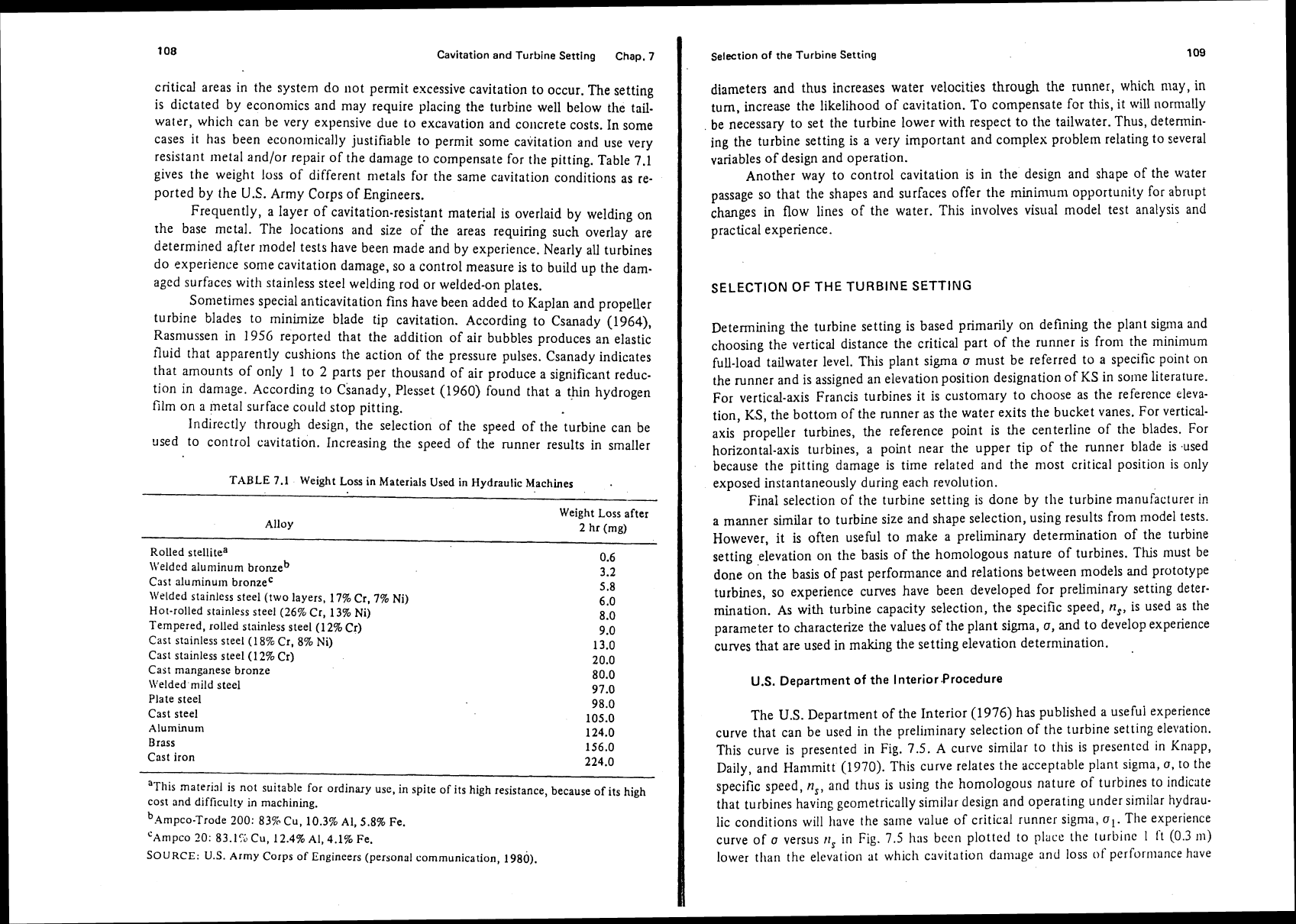
TABLE 7.1 Weight Loss in Materials Used in Hydraulic Machines
.
-
Weight Loss after
Alloy
2 hr (mg)
Rolled stellitea
0.6
\Veldcd alunlinum bronzeb
3.2
Cast aluminum bronzeC
5.8
Welded stainless steel (two layers, 17% Cr, 7% Ni)
6.0
Hot-rolled stainless steel (26% Cr, 13% Ni)
8.0
Tempered, rolled stainless steel (12%
Cr)
9.0
Cast stainless steel
(18%
Cr,
8%
Ni)
13.0
Cast stainless steel (12% Cr)
20.0
Cast manganese bronze
80.0
\\'elded mild steel
97.0
Plate steel
98.0
Cast steel
105.0
Aluminum
124.0
Brass 156.0
Cast iron
224.0
"This
materid is not suitable for ordinary use, in spite of its high resistance, because of its high
cost and difficulty in machining.
b.4mpco-~rode 200: 83% Cu, 10.3% Al, 5.8% Fe.
'Ampco 20: 83.15 cu, 12.4% Al, 4.1% Fe.
SOURCE:
U.S.
Army Corps of Engineers (personal communication, 1980).
Selection
of
the
Turbine Setting
109
diameters and thus increases water velocities through the runner, which may, in
turn, increase the likelihood of cavitation. To compensate for this, it will normally
be necessary to set the turbine lower with respect to the tailwater. Thus, detennin-
ing the turbine setting is a very important and complex problem relating to several
variables of design and operation.
Another way to control cavitation is in the design and shape of the water
passage so that the shapes and surfaces offer
the minimum opportunity for abrupt
changes in flow lines of the water. This involves visual model test analysis and
practical experience.
SELECTION OF THE TURBINE SETTING
Determining the turbine setting is based primarily on defining the plant signla and
choosing the vertical distance the critical part of the runner is
from the minimum
full-load tailwater level. This plant sigma
o
must be referred to a specific point on
the runner and is assigned an elevation position designation of KS in
some literature.
For vertical-axis Francis turbines it is customary to choose as the reference eleva-
tion,
KS,
the bottom of the runner as the water exits the bucket vanes. For vertical-
axis propeller turbines, the reference point is the centerline of the blades. For
horizontal-axis turbines, a point near the upper tip of the runner blade is
.used
because the pitting damage is time related and the most critical position is only
exposed instantaneously during each revolution.
Final selection of the turbine setting is done by the turbine manufacturer in
a manner similar to turbine size and shape selection, using results from model tests.
However, it is often useful to make a preliminary determination of the turbine
setting elevation on the basis of the homologous nature of turbines.
This must be
done on the basis of past
performance and relations between models and prototype
turbines, so experience curves have been developed for preliminary
setring deter-
mination. As with turbine capacity selection, the specific speed,
n,,
is used as the
parameter to characterize the values of the plant sigma,
a,
and to develop experience
curves that are used in making the setting elevation determination.
U.S.
Department of the Interior Procedure
The
U.S.
Department of the Interior (1976) has published a usefui experience
curve that can be used in the preliminary selection of the turbine setting elevation.
This curve is presented in Fig. 7.5.
A
curve similar to this is presented in Knapp,
Daily, and
Hammitt (1970). This curve relates the acceptable plant sigma,
o,
to the
specific speed,
n,,
and thus is using the homologous nature of turbines to indicate
that turbines having geometrically similar design and operating under similar hydrau-
lic conditions will
have the same value of critical runner sigma,
a,.
The experience
curve of
a
versus
r~,
in Fig. 7.5 h:is bccn plotted to place the lurbinc
1
ft
(0.3 ~n)
lower than the elevation at which cavitation damage and loss
of
performance have
Cavitation and Turbine Setting Chap.
7
I
Selection of the Turbine Setting
a
plant
<
a
turbine
0.02
/
10 20 40
60
80 100
Specific speed?,
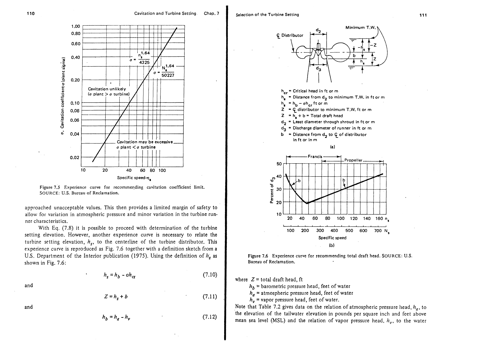
Figure
7.5
Experience curve for recommending cavitation coefficient limit.
SOURCE:
U.S.
Burcau of Reclarnation.
approached unacceptable values. This then provides a limited margin of safety to
allow
for variation in atmospheric pressure and minor variation in the turbine run-
ner characteristics.
With
Eq.
(7.8) it is possible to proceed with determination of the turbine
setting elevation. However, another experience curve is necessary to relate the
turbine setting elevation,
h,,
to the centerline of the turbine distributor.
This
experience curve is reproduced as Fig. 7.6 together with a definition sketch from a
U.S.
Department of the Interior publication (1975). Using the definition of
h;
as
shown in Fig. 7.6:
h,
=
hb
-
oh,
(7.10)
and
and
h,
=ha-h,
hcr
=
Critical head in ft or m
h,
=
Distance from
d2
to minimum
T.W.
in ft or m
h,
=
hb
-
ahcr ft or m
Z
=
distributor
to minimum T.W. ft or
rn
Z
=
h,
+
b
=
Total draft head
dl
=
Least diameter through shroud in ft or
m
d3
=
Discharge diameter of runner in
ft
or
rn
b
=
Distance from
d2
to %of distributor
in ft or in m
(a)
I.4.I.I.I..l..
,
100 200 300 400
500
600
700N,
Specific speed
(b)
Figure
7.6
Experience curve for recommending total draft head.
SOURCE: U.S.
Bureau of Reclamation.
where
Z
=
total draft head, ft
hb
=
barometric pressure head, feet of water
h,
=
atmospheric pressure head, feet of water
h,
=
vapor pressure head, feet of water.
Note that Table 7.2 gives data on the relation of atmospheric pressure head.
h,,
to
the elevation of the tailwater elevation in pounds per square inch and feet above
mean sea level
(MSL)
and the relation of vapor pressure head,
h,,,
to the water

112
Cavitation and Turbine Sening
Chap.
7
TABLE
7.2
Atmospheric Pressure and Vapor Pressure Variatio~~~
A
rrr~ospheric Pressure
Altitude
ha "a
Altitude
ha ha
(ft) (1b/in2) (ft H20) (m) (mm
Hg)
(m H20)
Water Vapor Pressure
Temp
h,
Temp
hv
C'F)
(ft)
("C)
(m)
atmospheric pressure for altitude, ft
(m);
h,,
vapor pressure of water (use highest expected
telnperature),
ft
(m);
Irb
=ha
-/I,,
atmospheric presscre rninus vapor pressure, It (m).
temperature. An example
problem
is
presented next to illustrate the use of the
experience curves as
an
approach to determining a turbine setting.
Example
7.1
Given:
A
hydro development is to operate at a maximum discharge of 1075 ft3/sec.
Normal tailwater elevation is 3 163.5 ft, head loss in the penstock is estimated to be
0.5 ft, normal headwater elevation is 3247 ft, and
minimum tailwater elevation is
3
158.5 ft. Maximum water temperature is 70'~.
Required: Find a suitable centerline elevation for the turbine runner.
.4nalysis and solution: First determine plant capacity, speed, and runner size.
php,
design capacity, can be determined from
Eq.
(3.6):
Assuming an efficiency,
e
=
0.90, we obtain
Selection of the
Turbine Setting
Using
Eq.
(4.17), we have
-
nP''.5
ns
-
-
J,
1.25
Next,
we solve for a preliminary value of speed n':
Taking a value for n, from
Fig.
4.3 when
hd
=
83 ft, n,
=
100, and
100(83)'~~
n
=
=
262.5 rpm
(9
1
1
I)'.'
Using the synchronous speed equation,
Eq.
(4.30),
7200
n=-
NP
the number of poles would be
Use the nearest even number of poles, 28, to obtain a synchronous speed.
7200
=-
=
257.1 rpm
28
Now find the actual n,.
For a propeller turbine
dh
d3
=
1 15.67nit3-
from Eq. (4.35)
n
=
87.12 inches
=
7.26 feet
Now, using Fig. 7.5, solve for a limiting plant sigma,
a:
11'0~~
(97.96)1.64
,=S=
=
0.426
4325 4325

114
Cavitation and Turbine Setting Chap.
7
interpolating
h,
from Table 7.2
is
=
30.26 ft
Also from Table 7.2,
h,
=
0.84
Using Eq. (7.1 2), we then have
h,
=
ha
-
h,
=
30.26
-
0.84
=
29.42 ft
In this case the normal elevation of the headwater is taken for maximum headwater
elevation to calculate
h,.
h,=3247-3158.5-0.5~88 ft
so that from Eq.
(7.10),
From Fig. 7.6,
b
=
Kd3
and
K
for this case is
n,
=
97.96
K
=
0.284
so
tl~nt
b
=
(0.284)(7.26)
=
2.06 ft and
Elevation of
centerline of runner
=
3
158.5
-
8.07
+
2.06
=
31
52.6
ft
ANSWER
U.S.
Army
Corps of Engineers Procedure
Tlie Corps of Engineers
method recognizes that there must be a limiting or
starting value for defining the cavitation coefficient,
o.
This value is called
critical
plant
sigma
and requires that model testing has been done to generate efficiency
versus
signla curves. The Corps of Engineers defines critical runner sigma as the
point at which there occurs a
1%
decrease in power or efficiency, whichever occurs
first.
This definition follows the pattern defined in Fig.
7.4.
Some turbine units do not have the typical cavitation curves of Fig. 7.3 and
the shapes may vary as shown in Fig. 7.4. For cavitation curves of these different
fomis, tlle Corps of Engineers has arbitrarily defined critical runner sigma, a,,
indicated as
al,
in Fig. 7.4, and has taken the higher value that is determined in such
a
grapl~ical evaluation. Because of the uncertainty involved, such as knowledge of
the prototype temperature, it is customary to work with a safety margin. The Corps
of Engineers
defmes safety margin, SM, as being equal to the minimum difference
(in feet of water) between critical
sigma and plant sigma, expressed in equation
fonn as
ShI
=
h(up
-
a,)
(7.13)
Selection of the Turbine Setting
115
Physically, the plant sigma is fixed by the turbine setting and the operating level of
the tailwater with respect to the headwater level. The Corps of Engineers also
specifies the reference point or elevation, KS, for determining plant sigma. For
vertical-axis Kaplan turbines and propeller turbines, the reference point is the
centerline of the blades. For vertical-axis Francis turbines, the point is usually the
bottom of the runner vanes or at the top of the draft tube. For horizontal-axis
machines, the upper tip of the runner blade may be used.
Most purchasers of turbines require a guarantee of performance with respect
to cavitation. Recognizing that it is almost impossible to have turbines operate free
of cavitation, the guarantee is usually expressed in a maximum rate of metal removal
during the guarantee period,
usually one year. The maximum metal removal rate
allowed for mild steel by the U.S. Corps of Engineers contracts is
0.~~/8000 lb
per operating hour each year, where
D
equals the runner diameter in feet.
A
lower
rate of 0.02D2/8000 lb is usually specified for stainless steel
runners. This includes
the runner and other parts of the turbine
installation, such as the discharge ring. To
illustrate the
U.S.
Corps of Engineers method,
an
example problem is presented
next.
Example
7.2
Given: A proposed hydro development is to have four horizontal-shafted 5-MW
turbines that will be operating under a rated net head of 16 ft. The turbine runners
have been preliminarily sized at a diameter of
J3
=
217 in., with a speed,
n,
of 54.5
rprn. The atmospheric pressure head,
It,,
is 33.7 ft of water; the vapor pressure
head,
h,,
is 0.6 ft of water; andl the minimum tailwater elevation is 416 ft MSL.
Figure 7.7 shows the results of a model test for
a
unit of the proper specific speed
for the given site conditions.
Required: Using the model test curve of Fig. 7.7, find the following:
(a) Required turbine
centedine elevation allowing for a safety margin of 10 ft
(b) Safety margin if the turbine is operated under a head of 13 ft
(c) Turbine horsepower output at the rated head
In developing the model curves the following definition of speed coefficient,
I$,
and unit power,
pl,
were used:
ndP
+=--
[see Eq. (4.3)]
1839
&
(G'~)'
p,
=
p
--
-
[from Eq. (4.1311
Dm
hl.5
where
dp
=
prototype runner di;~n~eter, in.
D,,
=
model runner dia~neter, in.
=
12 in.
Cavitation and Turbine Setting
Chap.
7
Speed ratio,
9
900
Gate d&ning
i4
mm
I
I-lr
Physical limit
for head,
angle
-
1.3
and gate opening
1.5
1.7
1.9
0
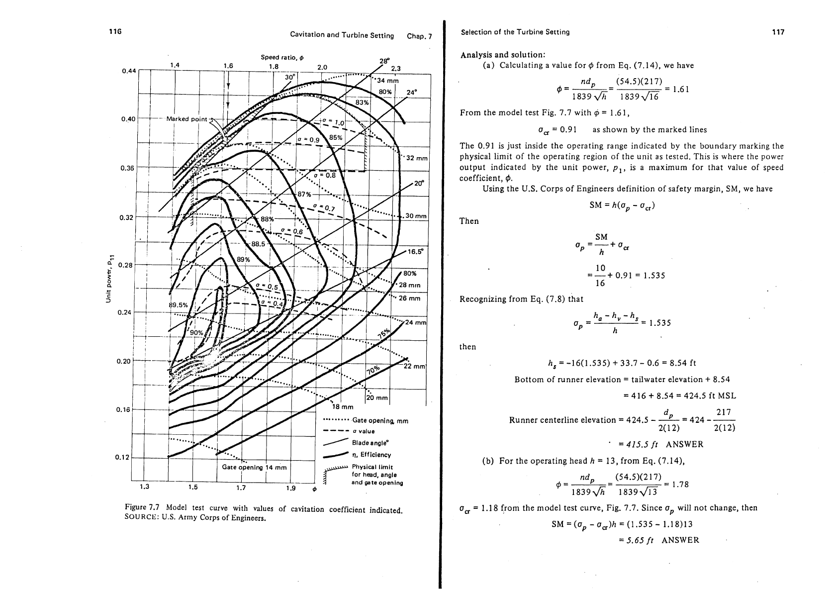
Figure
7.7
Model test curve with values of cavitation coefficient indicated.
SOURCE:
U.S.
Army
Corps of Engineers.
Selection of the Turbine Setting
Analysis and solution:
(a) Calculating a value for
,#,
from
Eq.
(7.14),
we have
nd~
$=--
(54.5)(2 17)
1839~- 1839a
=
1.61
From the model test Fig.
7.7
with
@
=
1.6
1,
a,
=
0.91
as shown by the marked lines
The
0.91
is just inside the operating range indicated by the boundary marking the
physical limit of the operating region of the unit as tested. This is where the power
output indicated by the unit power,
pl,
is
a maximum for that value of speed
coefficient,
4.
Using the U.S. Corps of Engineers definition of safety margin,
SM,
we have
SM
=
h(ap
-
a,,)
Then
SM
'p
=T+
Ow
Recognizing from
Eq.
(7.8)
that
then
h,=-16(1.535)
+
33.7
-
0.6
=
8.54
ft
Bottom of runner elevation
=
tailwater elevation
+
8.54
=
416
+
8.54
=
424.5
ft MSL
dP
-
2 17
Runner centerline elevation
=
424.5
-
-
-
424
-
-
2(
12)
2(
12)
=
415.5
ft
ANSWER
(b)
For the operating head
h
=
13,
from
Eq.
(7.14),
ndp (54.5)(2 17)
,#,
=
-----
-
=
1.78
18396- 1839fi
a,
=
1.18
from the model test curve, Fig.
7.7.
Since
up
will not change, then
SM=(ap -aa)h=(1.535- 1.18)13
=5.65
ft
ANSWER
118
Cavitation and Turbino Setting Chap.
7
This is less than the specified v;ilue of 10 ft, so the setting may need to be modified
and
bc
governed by the minimum operating head,
timin.
(c) At rated Iiead,
hd,
of 16 ft,
pi
=
0.38 from the model curve Fig. 7.7.
Using
Eq.
(7.1 5) yields
=
0.38
-
(16)'.5
=
7953
11p
ANSWER
(21:s
Assuming a generator efficiency of 0.97 at maximum output, the kilowatt power
output should be
P,,
=
(0.97)(0.746)(7953)
=
5750
kW
Based on the rated output of 5
MW,
this indicates
and that the turbines would be operating at 115% of rated capacity, which is quite
common in
U.S.
Army Corps practice.
,
One caution should be mentioned: this method assumes that model test data
are available. The
US.
Corps of Engineers has,as a result of normal contract require-
ments,
accu!nulated a representative group of such curves, but normally model test
curves are not readily available.
A
method of estimating the value of critical sigma
should be obtained and
tl~us experience curves like Fig. 7.5 are useful.
Manufacturers' Procedures
Each manufacturer has sets of model test curves for its own designs so that an
approach to determining turbine setting can be
similar to that of the U.S. Corps of
Engineers method.
One company, KaMeWa of Sweden
(Li~ldestroni, n.d.), givcs a useful approach
for preliminary planning which is more a rule-of-thumb approach: that the
sub-
liiergence of the unit ceriterline should be
where
Z
=
total suction head, m
D
=
runner diameter,
m
K
increasing from
K
=
0.5 for a design net head
Hd
of 10 m to
K
=
1.0 for a
Hd
=
30 m net head. This is for vertical-axis machines and would riormally apply
for
Kaplari and fixed-blade turlines.
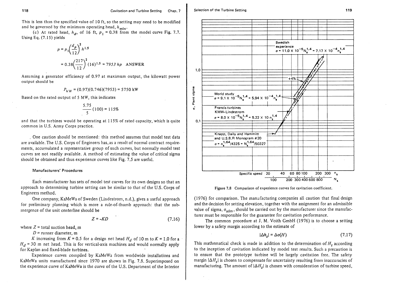
Experie~ice curves colnpiled by KaMeWa from worldwide installations and
KaMeWa units nianufactured since 1970 are shown in Fig. 7.8. Superimposed on
the experience curve of KaMeWa is the curve of the
U.S. Department of the Interior
Selection of the Turbine Setting
119
Swedish
experience
-
a=
11.0~ 10-~~1'~=7.17
x
10-~n1'~
Francis turbines
A*'
I
I
I
KMW-
Lindestrorn
11
I
I
I
f
111
I
I
Knapp, Daily and Harnmitt
f-t/
1
I
I
1
I
and U.S.B.R Monogram #20
1.64
o
=
n 14325
-
~:'~~/50327-
Specific speed 20 40
60
80 100 200 300
n,
I
I
IIIII
100 200 300 400 600 800
N,
Figure
7.8
Comparison of experience curves for cavitation coefficient.
(1976) for comparison. The manufacturing companies all caution that final design
and the decision for setting elevation, together with the assignment for an admissible
value of sigma,
uadm,
should be carried out by the manufacturer since the manufac-
turer must be responsible for the guarantee for cavitation performance.
The common procedure at
J.
M.
Voith Gmbl-I (1976) is to choose a setting
lower by a safety margin according to the estimate of
This mathematical check is made in addition to the determination of
H,
according
to the inception of cavitation indicated by model test results. Such a precaution
is
to ensure that the prototype turbine will be largely cavitation free. The safety
margin
lAH,I
is chosen to compensate for uncertainty resulting fro111 illaccuracies of
manufacturing. The amount of
IAH,I
is chosen with consideration of turbine speed,
120
Cavitation
and
Turbine Setting Chap.
7
n,
and the rated and operating heads.
J.
M.
Voith GmbH recommends that a value
of Aa
=
0.1 for low-specific-speed turbines and a
Aa
=
0.2
for high-specific-speed
turbines be used. For an operating head of
50
m, this results in
lAH,I
=
10
m.
For Francis runners,
J.
M.
Voith GmbH indicates that it is possible, without
serious trouble, to apply the principle that
up
>
akg. The ubeg is the first visual
indication of cavitation.
REFERENCES
Arndt,
R.
E.
A., "Cavitation in Fluid Machinery and Hydraulic Structures,"
Anrlual
Review of Fluid Mechanics,
Vol. 13, 198 la.
-
"Recent Advances in Cavitation Research," In
Advances in Hydroscience,
Vol.
12, V. T. Chow, ed. New York: Academic Press,
1981b.
Csanady,
G.
T.,
Theory of Turbornachinery.
New York: McCraw-Hill Book Com-
pany, 1964.
Eichler,
O., and E.
-U.
Jaeger, "The Assessment of Cavitation Behavior of Kaplan
Turbines on the Basis of a Comparison between Model Tests and Field
Ex-
perience,"
Voith Research and Construction,
Vol. 25e, Paper
4,
Reprint t2365e,
1979.
Knapp,
R.
T.,
and
A.
Hollander, "Laboratory Investigation of the Mechanism of
Cavitation,"
Transactions, American Society of Mectlanical Engineers,
Vol. 70,
1948.
Knapp,
R.
T.,
J.
W.
Daily, and
F.
G.
Hammitt,
Cavitation.
New York: McCraw-Hill
Book Conipany, 1970.
Lindestrom, L.
E.,
"Review of Modem Hydraulic Turbines and Their Application
in Different Power Projects,"
AB Karlstads Mekaniska Werkstad,
Kristineham,
Sweden:
KaMeWa, n.d.
Plessett,
M.
S.,
"On Cathodic Protection in Cavitation Damage,"
Transactions,
American Society of Mechanical Engineers,
Vol. 82, Ser.
D,
No. 4, 1960.
U.S.
Department
of
the Interior, "Lesson No.
11,
Hydraulic Turbines,"
Training
Course of Power Operating Personnel.
Denver, Colo.: Bureau of Reclamation,
Engineering Research Center, 1975.
U.S.
Department of the Interior, "Selecting Hydraulic Reaction Turbines,"
A
Water Resources Technical Publication,
Engineering Monograpll No.
20.
Denver,
Colo.: U.S. Department of the Interior, Bureau of Reclamation, 1976.
J.
M.
Voith GmbH, "Cavitation-Setting and Definitions,"
Directives by the Depart-
ment.
kieidenheim, West Germany:
I.
M.
Voith GmbH, October 1976.
PROBLEMS
7.1.
Using the data in Example 7.1, determine the satisfactory turbine setting
centerline elevation
if
a synchronous speed of
277
rpnl
is
chosen instead of
rl
=
257.1
rpm. Comment on what variation
in
speed does to project cost.
Chap.
7
Problems
7.2.
A
hydro installation is planned for which the full-gate output of the turbine
would be
6000
kW
under a rated net head of 18 ft. It is proposed to have a
diameter of 203
in.
and to operate at a speed of
60
rpm. Assume that the
turbine is to be
homologo~is to the model for which curve data are available
in
Fig. 7.7. Select a satisfactory turbine setting with a safety margin of 8 ft if
the minimum tailwater elevation is
1000 ft MSL and the maximum water
temperature is
60'~.
Consider that the model turbine diameter,
d,
is
12
in.
7.3.
Using a method other than the U.S. Corps of Engineers procedure, check the
setting elevation determined in Problem 7.2. For that problem, what would
be the turbine discharge at full gate?
7.4.
Obtain data from a power plant
in
your vicinity and determine the plant
sigma at
minimum tailwater and maximum power output. Compare your
results with limiting values as indicated by Fig. 7.5 or Fig. 7.8.
I
Penstocks
Necessary components of the hydraulic turbines in a hydropower installation are
specially designed water passages and gates for controlling and directing the water
as it flows to, through, and from the turbines. The principal features to consider in
engineering feasibility and design studies are the flumes, penstocks, gates and valves,
spiral cases, and draft tubes.
OPEN
FLUMES
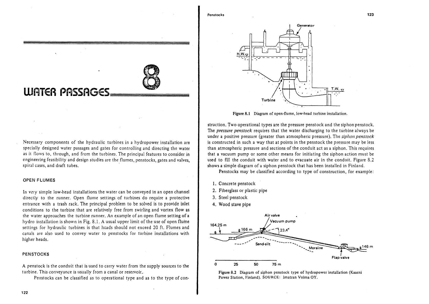
In vzry simple low-head installations the water can be conveyed in an open channel
directly to the runner. Open
flume settings of turbines do require a protective
entrance with a trash rack. The principal problem to be solved is to provide
inlet
conditions to the turbine that are relatively free from swirling and vortex flow as
the
water approaches the turbine runner.
An
example of an open flume setting of a
hydro installation is shown in Fig.
8.1.
A
usual upper limit of the use of open flume
settings for hydraulic turbines is that
hcads shou!d not exceed
20
ft. Flumes and
canals are also used to convey water to penstocks for turbine installations with
higher heads.
PENSTOCKS
A
penstock is the conduit that is used to carry water from the supply sources to the
turbine. This conveyance is
~~sually from a canal or reservoir..
Penstocks can be classified as to operational type and as to the type of con-
/:,&
'-,
'
'7,T.w.
-
-.
--
Turbine
..
.. .
Figure
8.1
Diagram of open-flume, low-head turbine installation.
struction. Two operational types are the pressure penstock and the siphon penstock.
The
pressure pensrock
requires that the water discharging to the turbine always be
under
a
positive pressure (greater than atmospheric pressure). The
siphoi~ penstock
is constructed in such a way that at points in the penstock the pressure may be less
than atmospheric pressure and sections of the conduit act as a siphon. This requires
that
a
vacuum pump or some other means for initiating the siphon action must be
used to fill the conduit with water and to evacuate air in the conduit. Figure
5.2
shows a simple diagram of a siphon penstock that has been installed in Finland.
Penstocks may be classified according to type of construction, for example:
1.
Concrete penstock
2.
Fiberglass or plastic pipe
3.
Steel penstock
4.
Wood stave pipe
Ai:
valve
/,vacuum pump
164.25
m
Flap
halve
Figure
8.2
Diagram of siphon penstock type of hydropower installation (Kaarni
Power Station, Finland). SOURCE: Imatran
Volrna
OY.
124
Water Passages
Chap.
8
Cast-in-place or precast reinforced concrete pipe can be used for penstocks.
Very large
diarlieters are somewhat impractical. Cast-in-place concrete pipes are
usually
limited to heads of less than 100 ft. According to Creager and Justin (1950),
precast reinforced concrete penstocks can be used up to 12.5 ft in diameter and
under heads up to 600 ft by using a welded steel shell embedded in the reinforced
concrete.
Fiberglass and polyvinyl chloride (PVC) plastic pipe have proven to be useful
for penstocks. A penstock at the Niagara Mohawk plant uses a fiberglass pipe 10 ft
(3
m) in diameter.
Wood stave pipes have been used in diameters ranging from
6
in. up to 20 ft
and utilized at heads up to 600 ft with proper design. Useful information for the
design of wood stave pipes is contained in the handbook by Creager and Justin
(1950).
Steel penstocks have become the most common type of installation in hydro-
power developments due to simplicity in fabrication, strength, and assurance that
they will perform in a wide variety of circumstances. Normal practice is to use
welded steel pipe sections. An excellent U.S. Department of the Interior mono-
graph
(1967)
treats the topic of steel penstocks. This covers the many details of
making selection of size and design considerations as to stresses and structural
mounting.
For purposes of engineering feasibility and preliminary design, there are three
majoi considerdtions that need engineering attention: (1) the head loss through the
penstock, (2) the safe thickness of the penstock shell, and
(3),
the economical size
of tlie penstock. Another consideration might be the routing of the penstock.
i-lead
Loss
in
Water
Passages
The head losses consist of the fo!lowing:
1. Trash rack losses
2. Entrance losses
3.
Stop log, gate slot, and tramition losses
4.
Friction losses in the pipe
5. Bend losses
According to the U.S. Department of the Interior
(1967), losses in trash rack and
entrance can be taken at 0.1, 0.2, and 0.5 ft of head, respectively, for velocities of
1.0, 1.5, and 2.5 ft/sec at the penstock entrance.
Dlgineering Alorlograph
No.
3
iurther indicates that entrance losses for bell-mouthed entrances would be 0.05 to
0.i
times the velocity head at entrance and for square-mouthed entrances the loss
\vould be 0.1 times the velocity head at entrance.
Pipe
flictlon losses can be determined by several reliable equations, mono-
g~.lplls, and tables that are available In llydraulic literature. Equations that are sug-
gested for use are
p~esented here in tlieir usual from:
Penstocks
Scobey equation:
where
hf
=
head loss, ft per 1000 ft of pipe
K,
=
loss coefficient
V=
velocity of flow in pipe, ft/sec
D
=
diameter of pipe, ft
The
K,
varies from 0.32 for new smooth pipe to 0.52 for rough pipe. More precise
values for
K,
can be obtained from various handbooks.
Manning equation:
and
where
R
=
hydraulic radius, A/P, ft
A
=
cross-sectional area of pipe, ft2
P=
wetted perimeter of pipe, ft
S
=
slope of hydraulic grade line
hf
=
head loss in pipe, ft
L
=
length of pipe, ft
n
=
roughness coefficient.
The
n
varies from 0.010 for smooth pipes to 0.017 for rough pipes. More precise
values for
n
can be obtained from various handbooks and suppliers' literature for
fiberglass and plastic pipe.
Darcy- Weisbach equation:
where
hf
=
head loss in pipe, ft
.
f
=
a numerical friction factor
g
=
acceleration of gravity, ft/sec2.
According to the U.S. Department of the Interior (1977). Colebrook and
White have developed an equation that relates the friction factor to pipe character-
istics and Reynolds number. The equation is difficult to use to get the friction
factor,
f,
directly. For more practical use of the equation, a diagram has been
developed for obtaining the friction factor,
f.
This is often referred to as a Moody
or
Stanton diagram (Moody, 1944; Rouse, 1943). A practical presentation
of
this
type of diagram for determining head loss in pipes is presented by the U.S. Depart-
ment of the Interior (1977). This is presented at
a
good scale for concrete pipes,
126
Water Psssagcs
Chap.
8
steel and cast iron pipes, riveted steel pipes, and woad stave pipes.
An
often useful
initial approach
can
be to use
f=0.02
in the Darcy-Weisbach equation to get a
beginning
estimate ofhead loss.
11
more rcccnt sopliisticated approach to solving for
head loss utilizing the equations of Colebrook and White is
the work of Barr
(1976).
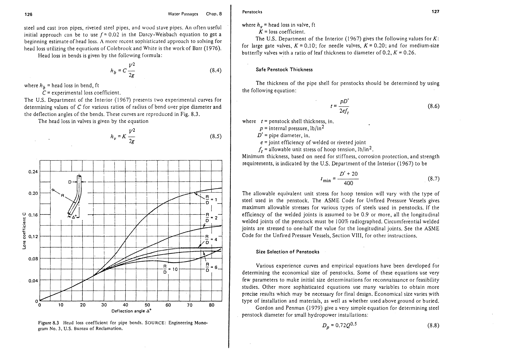
I-lead loss in bends is given by tlie follcwing formula:
where
hb
=
head loss in bend, ft
C
=
experimental loss coefficient.
The U.S. Department of the Interior
(1967)
presents two experime~ital curves for
determining values of
C
for various ratios of radius of bend over pipe diameter and
the deflection angles of the bends. These curves are reproduced in Fig.
8.3.
The head loss in valves is given by the equation
"
0 10
20
30
40
50
60
70
80
Deflection angle
A'
Figure
8.3
Head
loss coefficient for pipe bends.
SOURCE:
Engineering Mono-
gram No.
3.
U.S.
Burcnu of Reclamation.
Penstocks
127
where
h,
=
head loss in valve, ft
K
=
loss coefficient.
The
U.S.
Department of the Interior
(1
967)
gives the following values for
K:
for large gate valves,
K
=
0.10;
for needle valves,
K
=
0.20;
and for riiedium-size
butterfly valves with a ratio of leaf thickness to diameter of
0.2,
K
=
0.26.
Safe Penstock Thickness
The thickness of the pipe shell for penstocks should be determined by using
the following equation:
where
t
=
penstock shell thickness, in.
p
=
internal pressure, lb/in2
D'
=
pipe diameter, in.
e
=joint efficiency of welded or riveted joint
f,
=allowable unit stress of hoop tension, 1b/in2.
Minimum thickness, based on need for stiffness, corrosion protection, and strength
requirements, is indicated by the U.S. Department of the Interior
(1967)
to be
The allowable equivalent unit stress for hoop tension will vary with the type of
steel used in the penstock. The
ASME Code for Unfired Pressure Vessels gives
maximum allowable stresses for various types of steels used in penstocks. If tlie
efficiency of the welded joints is assumed to be
0.9
or more, all the
longitudinal
welded joints of the penstock must be
100%
radiographed. ~ircumferential welded
joints are stressed to one-half the value for the longitudinal joints. See the
ASh1E
Code for the Unfired Pressure Vessels, Section VIII, for other instructions.
Size Selection of Penstocks
Various experience curves and empirical equations have been developed for
determining the economical size of penstocks. Some of these equations use very
few parameters to make initial size deterrninations for reconnaissance or feasibility
studies. Other more sophisticated equations use many variables to obtain more
precise results which may be necessary for final design. Economical size varies with
type of installation and materials, as well as
wlietlier used above ground or buried.
Gordon and Penman
(1979)
give
a
very slmple equation for determining steel
penstock diameter for small hydropower installations: