Warnick C.C. Hydropower engineering
Подождите немного. Документ загружается.

Pressure Control and Speed Regulation
Chap.
10
seed settin;
7
Wlcket gates
9
-
-
Relay valve Servomotor
Figure 10.1
6
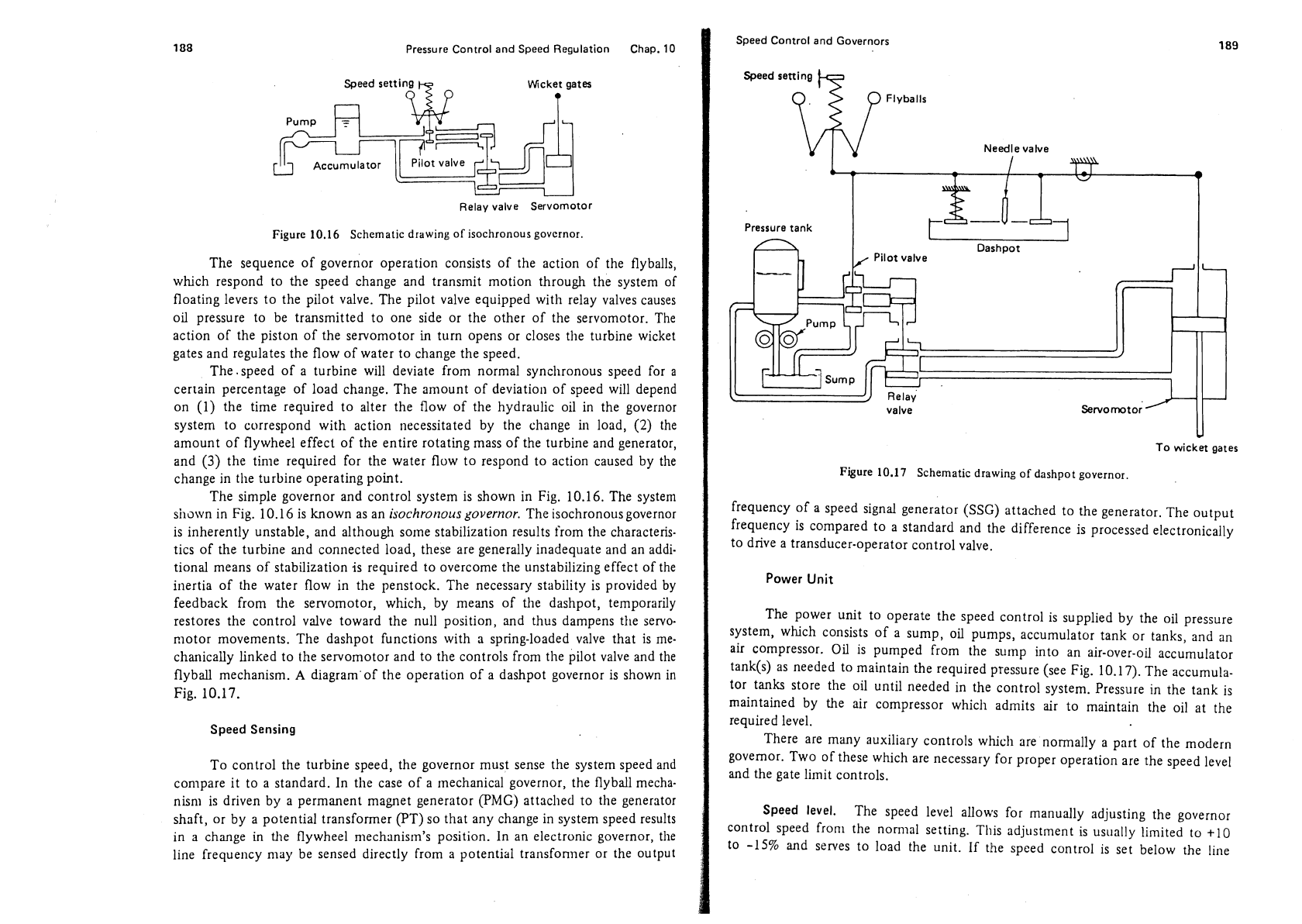
Schematic drawing of isochronous governor
The sequence of governor operation consists of the action of the flyballs,
which respond to the speed change and transmit motion through the system of
floating levers to the pilot valve. The pilot valve equipped with relay valves causes
oil pressure to be transmitted to one side or the other of the servomotor. The
action of the piston of the servomotor in turn opens or closes the turbine wicket
gates and regulates the flow of water to change the speed.
The .speed of a turbine will deviate from normal
syncllronous speed for
a
certain percentage of load change. The amount of deviation of speed will depend
on (1) the time required to alter the flow of the hydraulic oil in the governor
system to correspond with action necessitated by the change in load,
(2)
the
amount of flywheel effect of the entire rotating mass of the turbine and generator,
and
(3)
the time required for the water flow to respond to action caused by the
change in the turbine operating point.
The simple governor and control system is shown in Fig. 10.16. The system
silown in Fig. 10.16 is known as an
isochrot~ous governor.
The isochronous governor
is inherently unstable, and although
some stabilization results from the characteris-
tics of the turbine and connected load, these are generally inadequate and an addi-
tional means of stabilization is required to overcome the unstabilizing effect of the
inertia of the water flow in the penstock. The necessary stability is provided by
feedback from the servomotor, which, by means of the
dashpot, temporarily
restores the control valve toward the null position, and thus dampens the servo-
motor movements. The
dashpot functions with a spring-loaded valve that is me-
chanically linked to the servomotor and to the controls from
the pilot valve and the
flyball mechanism.
A
diagram'of the operation of a dashpot governor is shown in
Fig. 10.17.
Speed Sensing
To control the turbine speed, the governor must sense the system speed and
compare it to a standard. In the case of a mechanical governor, the flyball mecha-
nisn~ is driven by a permanent magnet generator (PMG) attached to the generator
shaft, or by a potential transformer
(PT) so that any change in system speed results
in a change in
the flywheel mechanism's pcsition. In an electronic governor, the
line frequency may be sensed directly from a potential transformer or the output
I
Speed Control and Governors
I
Speed setting
n
Flyballs
Needle valve
I-
v
-'
Pressure tank
Dashpot
Pilot valve
U
To
wicket
gates
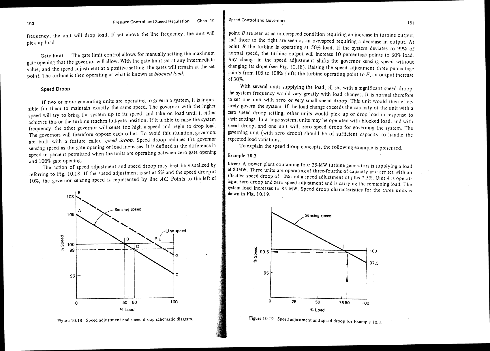
Figure
10.17 Schematic drawing of dashpot governor.
frequency of a speed signal generator (SSG) attached to the generator. The output
frequency is compared to a standard and the difference is processed electronically
to drive a transducer-operator control valve.
Power
Unit
The power unit to operate the speed control is supplied by the oil pressure
system, which consists of a sump, oil pumps, accumulator tank or tanks, and an
air compressor. Oil is pumped from the
sump into an air-over-oil accumulator
tank(s) as needed to maintain the required pressure (see Fig. 10.17). The accumula-
tor tanks store the oil until needed in the control system. Pressure in the tank is
maintained by the air compressor which admits air to maintain the oil at the
required level.
There are many auxiliary controls which are normally a part of the modern
governor. Two of these which are necessary for proper operation are the speed level
and the gate limit controls.
Speed level.
The speed level allows for manually adjusting the governor
control speed
from the norn~al seiting. This adjustment is usually limited to
t10
to -15% and serves to load the unit. If the speed control is set below the line
190
Pressure Control
and
Speed
Regulation
Chap.
10
frequency, thc unit will tlrop load. If set above the line frequency, tlie unit will
pick up load.
Gate limit.
The gate
limit control allows for manually setting the niaxirnum
gate opening that the governor will allow. With the gate liniit set at any intermediate
value, and the speed adjustment at a positive setting, the gates will remain at tlie set
point. The turbine is then operating at what is known as
blocked load.
Speed Droop
if
two or more generating units are operating to govern a system, it is impos-
sible for
them to maintain exactly the same speed. The governor with the higher
speed will try to bring the system up to its speed, and take
on load until it either
achieves this or the turbine reaches full-gate position. If it is able to raise the system
frequency, the other governor will sense too
high
a
speed and begin to drop load.
The governors will therefore oppose each other. To avoid this situation,
governon
are built with a feature called
speed
droop.
Speed droop reduces the governor
sensing speed as the gate opening or load increases. It is defined as the difference
in
speed in percent permitted when tlie units are operating between zero gate opening
and 100% gate opening.
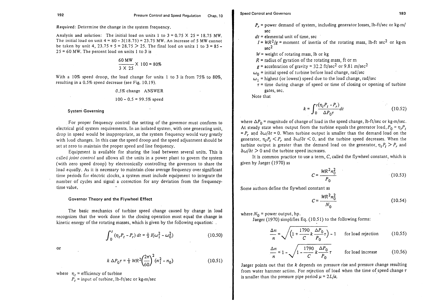
The action of speed adjustment and speed droop may best be visualized by
referring to Fie. 10.18. If the specd adjustment is set at 5% and the speed droop at
and 100% gate opening.
The action of speed adjustment and speed droop may best be visualized by
referring to Fig. 10.18. If the specd adjustment is set at 5% and the speed droop at
1076, the governor sensing speed is represented by line
AC.
Points to the left of
108
4
105
Line
100.
95
L
I
I
1
I
0 50 60 100
%
Load
Figure 10.18
Spccd adjustn~ent and specd droop sclicniatic
diagram.
Speed Control and Governors
191
point
B
are seen as an underspeed condition requiring an increase in turbine output,
and those to the right are seen as an overspeed requiring
a
decrease in output. At
point
B
the turbine is operating at 50% load. If the system deviates to
999
of
normal speed, the turbine output will increase 10 percentage points to 60% load.
Any change
in
the speed adjustment shifts the governor sensirlg speed without
changing its slope (see Fig.
10.15).
Raising tlie speed adjustment three percentage
points from 105 to 108% shifts the turbine operating point to
F,
an output increase
of
30%.
With several units supplying the load, all set with a significant speed droop,
the
system frequency would vary greatly with load changes. It is normal therefore
to
set one unit with zero or very small speed droop. Tllis unit would then
effec-
tively govern the system.
If
the load change exceeds the capacity of
the
unit wit11 a
zero speed droop setting, other units would pick up or drop load
ill response to
their settings. In a large system, units may be operated with blocked
load. and with
speed droop, and one unit with zero speed droop for governing the system.
The
governing unit (with zero droop) should be of sufficient capacity to Iinndle the
expected load variations.
To explain the speed droop concepts, the following example is
preserlted.
Example
10.3
Given:
A
power plant containing four
25-MW
turbine generators is supplying
a
load
of
80MW. Three units are operating at three-fourths of capacity and nre
Let
with
an
a,-ra,.&:%!a
..---A
A--
7p of 10% and a speed adjustment of plus
7.5%.
Unit
4
1s operat-
Given:
A
power plant containing four
25-MW
turbine generators is supplying
a
load
of
80MW. Three units are operating at three-fourths of capacity and nre
Let
with
an
effective speed droop of 10% and a speed adjustment of plus
7.5%.
Unit
4
1s operat-
ing at zero droop and zero speed adjustment and is carrying the
remaining
load.
The
system load increases to 85
MW.
Speed droop characteristics for the three unlts is
shown in Fig. 10.1
9.
d zero speed adjustment and is carrying the remaining load.
The
:s to 85
MW.
Speed droop characteristics for the three units is
%
Load
Figure 10.19 Speed
adjus:ment and spced droop
for
I<xnnlple
10.3.
%
Load
Figure 10.19 Speed
adjus:ment and spced droop
for
I<xnnlple
10.3.
192
Pressure Control and Speed Regulation Chap.
10
Required: Determine the change in the system frequency.
Analysis and solution:
The initial load on units
1
to
3
=
0.75
X
25
=
18.75 MW.
The initial load on unit
4
=
80
-
3(18.75)
=
23.75 MW.
An
increase of 5 MW cannot
be taken by unit
4,
23.75
+
5
=
28.75
>
25. The final load on units 1 to
3
=
85
-
25
=
60
MW.
The percent load on units 1 to
3
is
With a 10% speed droop, the load
change for units
1
to
3
is from 75% to 80%,
resulting in a 0.5% speed decrease (see Fig. 10.1
9).
0.5%
change ANSWER
100
-
0.5
=
99.5% speed
System Governing
For proper frequency control the setting of the governor must conform to
electrical grid
system requirements. In an isolated system, with one generating unit,
dlop
in
speed would be inappropriate, as the system frequency would vary greatly
with luad changes. In this case the speed droop and the speed adjustment should be
set at zero to maintain the proper speed and line frequency.
Equipment is available for sharing the load between several units. This is
called
joint control and allovis
all
the units in a power plant to govern the system
(with zero speed droop) by electronically controlling the governors to share the
load equally.
As
it is necessary to maintain close average frequency over significant
time periods fur electric clocks, a system must include equipment to integrate the
nunlber of cycles and signal a correction for any deviation from the frequency-
time value.
Governor Theory and the Flywheel Effect
The basic mechanics of turbine speed change caused by change
in
load
recognizes that the work done in the closing operation must equal the change
in
kinetic energy of the rotating masses, which is given by the following equation:
.
where
g,
=
efficiency of turbine
P,
=
input of turbine, Ib-ft/sec or kg-m/sec
Speed Control and Governors
193
Pr
=
power demand of system, including generator losses, Ib-ft/sec or kg-m/
sec
dt
=
elemental unit of time, sec
I
=
WR~/~
=
moment of inertia of the rotating mass, lb-ft sec2 or kg-m
sec2
W
=
weight of rotating mass, Ib or kg
R
=
radius of gyration of the rotating mass, ft or
m
g
=
acceleration of gravity
=
32.2
ft/sec2 or 9.81 m/sec2
w0
=
initial speed of turbine before load change, rad/sec
w1
=
highest (or lowest) speed due to the load change, rad/sec
7
=time during change of speed or time of closing or opening of turbine
gates,
sec.
Note that
where
APo
=
magnitude of change of load in the speed change, lb-ft/sec or kg-m/sec.
At
steady state when output from the turbine equals the generator load,
Po
=
q,P,
=
P,
and awlat
=
0. When turbine output is smaller than the demand load on the
generator,
qtPl
<
Pr
and awlat
<
0, and the turbine speed decreases. When the
turbine output is greater than the demand load on the generator,
qlPt
>
Pr
and
awlat
>
0 and the turbine speed increases.
It is
commori practice to use a term,
C,
called the flywheel constant, which is
given by Jaeger (1970) as
Some authors define the flywheel constant as
where
No
=
power output, hp.
Jaeger (1970) simplifies Eq. (10.51) to the following forms:
)
-
1
for load rejection
(10.55)
n
nSI_
J
1--k-T 1790
APo
for load increase (10.56)
n
C
PO
Jaeger points out that the
k
depends on pressure rise and pressure change resulting
from water
hammer action. For rejection of load when the time of.speed change
T
is smaller than thc pressure pipe period
p
=
2L/a,
Pressure Control and Speed
Regulation
Chap.
10
and for time of closure or speed change where
T
>
2L/a,
where
L
=
penstock lengths, ft
or
m
Vo
=
water velocity in pipelinc;ft/sec or m/sec
a
=
velocity of pressure wave, ft/sec or m/sec
Ho
=
steady-state head, ft or m.
The flywheel effect can be related to accelerating time,
Tm,
for the rotating
masses of the turbine by the following formula:
where
Po
is in kg-m/sec. The
U.S.
Department of the Interior (1976) gives the
fly.
wheel effect equation in the following form:
where
IV
is in pounds,
R
is in feet,
n
is
in
rpm, and
Php
is in hp. In metric form the
equation is
where
IV
is in kg,
R
is in meters,
n
is in rpm, and
PkW
is in
kW.
For
the purpose of preliminary planning it is important to define two other
terms. The first is
Tw,
the starting time of water column related to the water ham-
mer action, which is given by the formula
where
T,,,
=
starting time of water column, in seconds, and other terms are as de-
fined for Eq. (10.58). The second parameter of time is
Tg,
the equivalent servo-
mot01 opening or closing time. Hadley (1970) has shown that these terms can be
related to each other and to pressure rise in the turbine water passage
by
a curvi-
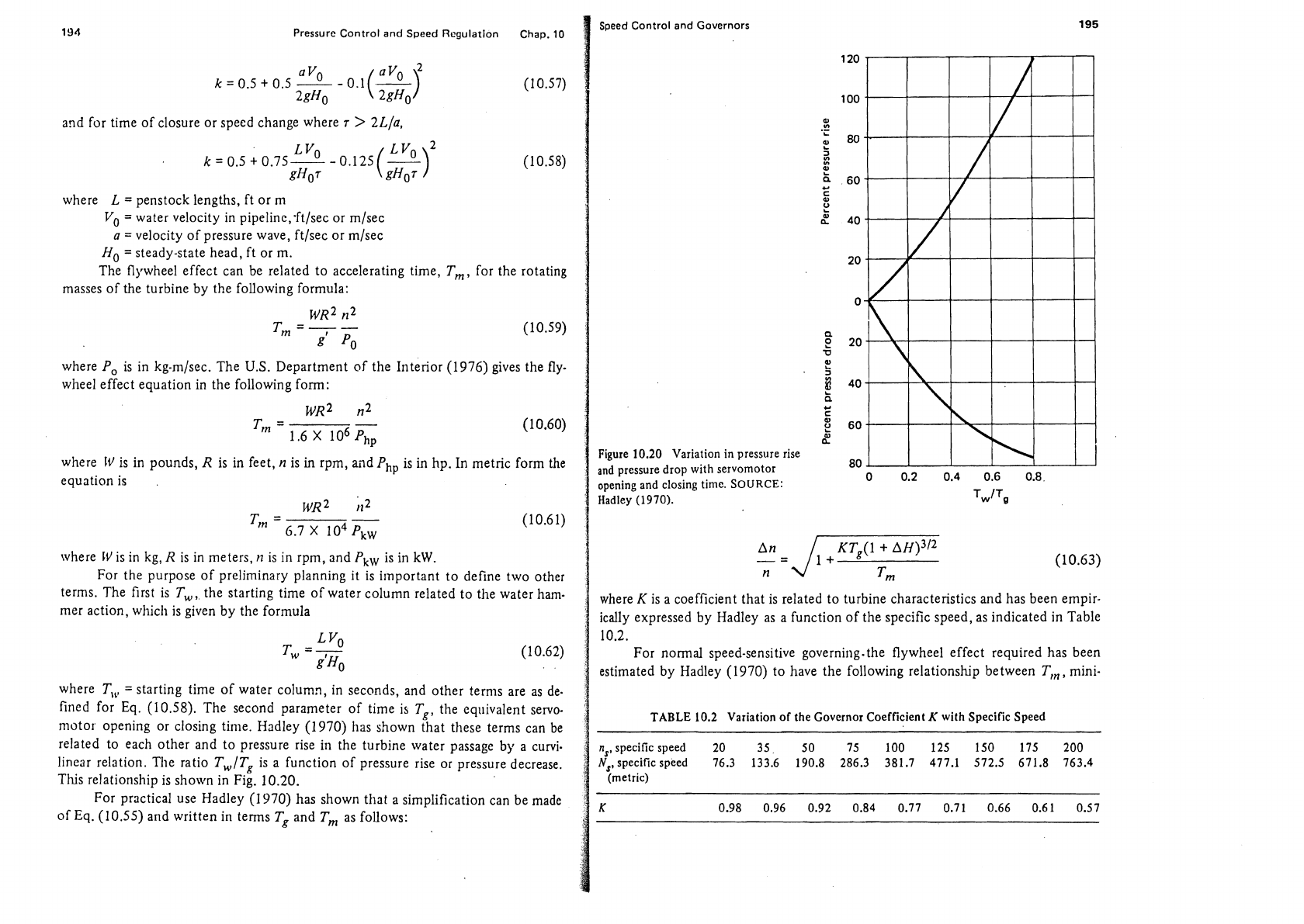
linear relation. The ratio
TWITg
is a function of pressure rise or pressure decrease.
This relationship is shown in Fig. 10.20.
For practical use
Hadley (1 970) has shown that a simplification can be made
of
Eq.
(10.55) and written in terms
Tg
and
Tm
as follows:
Speed Control and Governors
195
Figure
10.20
Variation in pressure rise
and pressure drop with servomotor
opening and closing time.
SOURCE:
Hadley
(1
9
70).
where
K
is a coefficient that is related to turbine characteristics and has been empir-
ically expressed by
Hadley as a function of the specific speed, as indicated in Table
10.2.
For
normal speed-sensitive governing.the flywheel effect required has been
estimated by
Hadley (1970) to have the following relationship between
T,,,
mini-
TABLE
10.2
Variation of the Governor Coefficient
K
with Specific Speed
n,,specific speed
20 35
50
75
100
125
150
175 200
N,,specificspeed
76.3 133.6 190.8
286.3 381.7
477.1 572.5 671.8
763.4
(metric)
I
Speed Control
and
Governors
Pressure Control
and
Speed Regulation
Chap.
10
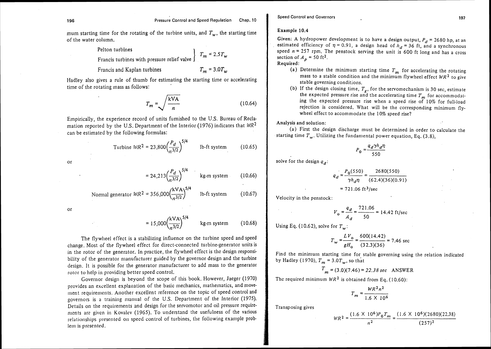
mum starting time for the rotating of the turbine units, and
T,,
the starting time
of
the water column.
Pelton turbines
I
T,,,
=
2.5TW
Francis turbines with pressure relief valve
Francis and Kaplan turbines
Tm
=
3.0Tw
Hadley also gives a rule of thumb for estimating the starting time or accelerating
time of the rotating
mass
as
follows:
Empirically, the experience record of units furnished to the
U.S.
Bureau of Recla-
mation reported by the
U.S.
Department of the Interior (1976) indicates that
FVR~
can be estimated by the following formulas:
Turbine
l~~l
=
23,8OO($Si4 ib-ft system (10.65)
=
24,213(2)514
.3/2
kg-m system (10.66)
~VA
514
Nomlal generator
WR~
356,000(~) Ib-ft system (10.67)
kg-m system (10.68)
The flywheel effect is a stabilizing influence on the turbine speed and speed
change. Most of the flywheel effect for direct-connected turbine-generator units is
in the rotor of the generator. In practice,
the flywheel effect is tlic design responsi-
bility of the generator manufacturer guided by the governor design and
the turbine
design. It is possible for the generator manufacturer to add mass to the generator
rotor to help in providing better speed control.
Governor design is
heyond the scope of this book. However, Jaeger (1970)
provides an excellent explanation of the basic mechanics,
matllelnatics, and move-
ment requirements. Another excellent reference on tile topic of speed control
and
governon is a training manual of the
U.S.
Department of the Interior (1975).
Details on
the
requirements and design for the servomotor and oil pressure require-
nlents are given in Kovalev (1965). To understand the usefulness of the various
relationships presented
011
specd control of turbines, the following example prob-
lem is presented.
I
Example
10.4
Given:
A
hydropower development is to have a design output,
Pd
=
2680 hp, at an
estimated efficiency of
77
=
0.91, a design head of
hd
=
36 ft, and a synchronous
speed
n
=
257 rpm. The penstock sewing the unit is 600 ft long and has a cross
section of
A,,
=
50 ft2.
Required:
(a) Determine the minimum starting time T, for accelerating the rotating
mass to a stable condition and the minimum flywheel effect
wR2 to give
stable governing conditions.
(b) If the design closing time,
Tg, for the servomechanism is 30 sec, estimate
the expected pressure rise and
the accelerating time Tm for accommodat-
ing the expected pressure rise when a speed rise of 10% for full-load
rejection is considered. What will be the corresponding minimum fly-
wheel effect to accommodate the 10% speed rise?
Analysis and solution:
(a) First the design discharge must be determined in order to calculate the
starting time
T,. Utilizing the fundamental power equation, Eq. (3.8),
I
Velocity in the penstock:
qd
721.06
y
=-=--
-
14.42 ft/sec
O
A,
50
Using
Eq.
(1
0.62), solve for T,
:
L
V,
600(14.42)
T
=-=
w
=
7.46 sec
gHo (32.3)(36)
Find the minimurn starting time for stable governing using the relation indicated
by
Hadley (1970), Tm
=
3.0Tw, so that
1
Tm
=
(3.0)(7.46)
=
22.38
sec
ANSWER
Thc
required minimum WR2 is obtained from Eq. (10.60):
Transposing gives
(1.6
x
1O6)p0T,,,
-
(1.6
X
1 06)(2680)(22.38)
WR~
=
n
2
(25712
Pressure Control and Speed Regulation
Chap.
10
h'~2
=
1.453
X
106 lb-ft2
ANSWER
(b) It is necessary to characterize the turbine and find specific speed
11,.
Using Eq. (4.17) gives us
To keep the relative speed
change
Anln
less than 0.10,
Eq.
(1 0.63) will apply.
n
d-
Tm
From Table 10.2 for
n,
=
150.9, Kz0.66. For Tg=30,
TWITg
=
7.46130
=
0.25,
and using Fig. 10.20 for
TWITg
=
0.25,
h
=
0.27.-Then
=
135 sec
ANSWER
Using Eq.
(1 0.62) again, we obtain
1.6
X
IO~P,T,,
-
(1.6
X
10~)(2680)(135)
WR~
=
(25712 (257)'
=
8.76
X
lo6
lb-ff2
ANSWER
REFERENCES
Allievi,
L.,
"Theory of Water Hammer,"
E.
Halmes, trans.,
Proceedings, Atnerican
Society of
mechanical
Engineers,
1925.
Araki,
M.,
and
T.
Kuwabara, "Analysis of Pump-Turbine System Including Pipe-
lines,"
Hifachi Review,
Vol. 24, No. 5, 1975.
Hadley,
B.,
"Governing of Water Turbines." Chapter V in
Hydro-electric Practice,
Vol. 2, 2d ed., G. Brown, ed. London: Blackie
8r
Son Ltd., 1970.
Jacobson,
R.
S., "Charts for Analysis of Surge Tanks in Turbines and Pump Installa-
tions,"
Report No.
104.
Denver, Colo.: U.S. Department of the Interior, Bureau
of Reclamation, 1952.
Jaeger,
C.,
"Governing of Water Turbines." Appendix 1 in
Hydro-electric Practice,
Vol. 2, 2d ed., G. Brown, ed. London: Blackie
&
Son Ltd., 1970.
Jordan, V., "Reverse Water Hammer in Turbine Draft Tubes,"
Water Power and
Darn Consfrttcfion,
Vol. 27, Nos. 2 and 3, 1975.
Joukovsky,
N.,
"Water Hammer,"
0.
Simin, trans.,
Proceedings, American Water
IVorks Association,
Vol. 24, 1904.
Kerr.
S.
L.,
and
E.
B.
Strowger, "Rksumk of Theory of Water Hammer in Simple
Conduits." In
Syrnposiutn on Water Han1tt:er.
New York: American Society of
Mechanical Engineers, 1933.
:hap.
10
Problems 199
:ovalev,
N.
N.,
Hydrottlrbines-Design and Construction,
1961,
M.
Segal, trans.
Jerusalem: Israel Program for Scientific Translation Ltd., 1965.
dcNown,
J.
S., "Surges and Water Hammer." In
Engineering Hydraulics,
11. Rouse,
ed. New York: John
Wiley
&
Sons, Inc., 1950.
dosonyi,
E.,
and
H, B.
S. Seth, "The Surge Tank-A Device for Controlling Water
Hammer,"
Water Power and Datn Construction.
Vol. 27, Nos. 2 and
3,
1975.
Ilechleba,
M.,
tlydraulic Turbines-Their Design and Equiptnent.
Prague: Artia/
London: Constable
&
Con~pany Ltd., 1957.
qemet,
A.,
"Mathematical Models of Hydraulic Plants,"
Escher 149~~s Ne\c.s,
No. 1,
1974.
'armakian,
J.,
Waterhammer Analysis.
Englewood Cliffs, N.J.: Prentice-Hall, Inc.,
1955.
Juick,
R.
S., "Comparison and Limitation of Various Water Hammer Theories,"
Mechanical Engineering,
ASME, Vol. 49, No. 5a, 1927.
itreeter, V.
L.,
and E.
B.
Wylie,
Fluid Mechanics,
7th ed. New York: McGraw-Hill
Book Company, 1979.
J.S. Army Corps of Engineers, "Water Hammer and Mass Oscillation
Sirrlulation
Program,"
Users Manual
CEG
002.
Washington, D.C.: Office of Chicf of
Engi-
neers, n.d.
J.S. Department of the Interior, "Welded Steel Penstocks,"
Er~pit~eerir~g il.lor~o-
graph No.
3.
Denver, Colo.: U.S. Department of the Interior, Bureau of Reclama-
tion, 1967.
J.S.
Department
of
the Interior, "Training Course for Power Operating Personnel,
Lesson
111, Governors for Hydraulic Turbines." Denver, Colo.: U.S. Department
of
the Interior, Bureau of Reclamation, 1975.
J.S. Department
of
the Interior, "Selecting Hydraulic Reaction Turbines,"
A
Water
Resource Technical Publication,
Engineering Monograph No.
20.
Denver, Coio.:
U.S. Department of the Interior, Bureau of Reclamation. 1976.
'ROBLEMS
10.1.
A
turbine installation has a normal design head of 50 ft, a velocity in the pen-
stock of 6
ftlsec, and a length of penstock from closure valvc to an open
water surface of 500 ft. Assume that the pressure wave velocity,
a.
is 3000
ftl
sec. Determine the relative preskre rise if closure is less than 0.1 scc. What is
the critical time of pressure wave travel? If the time of closure
1s
3
sec. what
will be the expected pressure rise and pressure drop?
10.2.
Visit a hydropower plant and determine the method of controlling water
hammer. Report on closure time of closing vaives or gates.
0.3.
A
simplified problem for a hydro plant involves a penstock of length 2500 ft,
the velocity of the penstock is 6
ftlsec, the penstock area is 100 ft2, the surge
tank area is proposed to be 2000 ft2, and the friction hcad loss in the pen-
stock
is
3
ft. Determine the approximate maximum pressure surgc
in
the
surge tank and time from beginning of flow until
maxiniurn surge if the gate
valve is suddenly closed.
200
Pressure Control and Speed Regulation Chap.
10
10.4.
Three turbine generators of
20
MW capacity are supplying a load of
48
MW
and the load suddenly increases to
50
MW. Two of thc units are set with
a
speed droop of
9%
and speed adjustment of
6%.
The third unit is operating
at zero speed droop and zero speed adjustment. Determine the change in
system frequency due to the sudden load change. What will the speed change
he if the load increases to
54
MW?
10.5.
For a small hydropower plant with a proposed servomotor opening time for
the
gates of not to exceed 12 sec, select a suitable penstock diameter if the
penstock is
1000
ft long and the turbine operates under a 60-ft head with
an
expected output of
5
MW. Determine a suitable design starting time,
T,,
expected pressure rise, and the minimum flywheel requirement. Make any
necessary assumptions.
POkLBERHOUSES
RNB
FAClLlBlES
TYPES OF POWERHOUSES
Powerhouses for hydroplants usually consist of the superstructure and the substruc-
ture. The superstructure provides protective housing for the generator and control
equipment as well as structural support for the cranes. The superstructure may
provide for
an
erection bay that protects component assemblies during 'inclement
weather.
The substructure or
foundatiofis of the powerhouse consists of the steel and
concrete components necessary to form the draft tube, support the turbine
stay
ring and generator, and encase the spiral case.
A
control room is also included in
the powerhouse to isolate the control systems from generator noise and to provide
a clean and comfortable
environrr~nt for operators.
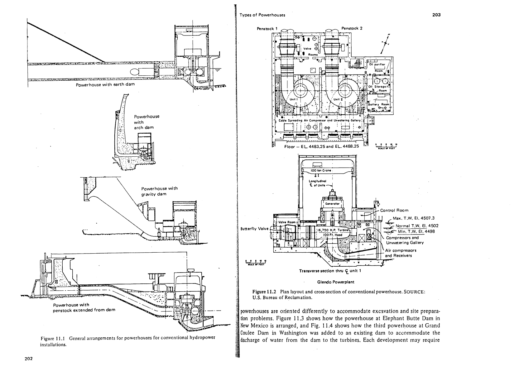
Conventional Installations
Conventional powerhouses differ depending on how they are oriented or con-
nected with the dam. Some are structurally connected to the dam; others are
located some distance from the dam and a penstock carries the water from the
intake to the powerhouse. Figure 11.1 is a
siniplified sketch of the general arrange-
ment for powerhouses of the conventional type. Different ways of connecting the
powerhouse to the impounding dam or the tunnel penstock are illustrated. Figure
11.2 is a plan layout and cross section for a typical powerhouse of the conventional
type showing the
arrangelnznt of the various components. The shaft of tlie runner
and generator is vertical and water flow is normal to the line of turbine units. Some
I
Powerhouse with earth
dam
owwhouse with
Figure
11
.I
General arrangements for powerhouses for conventional hydropower
installations.
rypes of Powerhouses
Butterfly
Valve
L.1
fY'f
-I
w
,887
ax.
T.W.
El.
4507.3
4
502
498
Transverse section
thru
tunit
1
Glendo Powerplant
Figure
11.2
Plan layout and cross-section of conventional powerhouse.
SOURCE:
U.S.
Bureau of Reclamation.
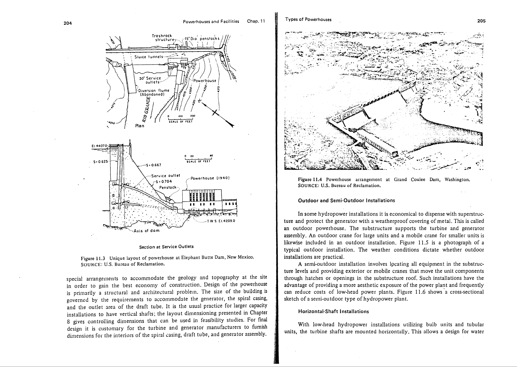
powerhouses are oriented differently to accommodate excavation and site prepara-
tion problems. Figure 11.3 shows how the powerhouse at Elephant Butte Dam in
New Mexico is arranged, and Fig. 11.4 shows how the third powerhouse at Grand
Coulee
Dam
in
Washington was added to an existing dam to accornniodate the
discharge of water from the dam to the turbines. Each development
rnay require
ialem ioj @sap e smo11c
S!L~J,
'A[lcluoz!ioq palunolu air! slje~[s au!qrnl aql 'sl!un
ielnqnl pue sl!un qrnq Bu!z![!gn suo!~c~~c~str! iamodoipAq peaq-MO~ ql!~
.luc[d iamodoipAq jo adL1 rooplno-yras c jo qslays
leuo!lsas-ssois c smoqs
9'1
1
arnS!d 'slucld ia~od pr!aq-MO[ jo slsos asnpar
ue3
Spuanbaij pue lue~d ia~od aql jo ainsodxa 3!laylsae arour e 8u1p!nold jo a8eluenpe
aql ahey suo!lel[elsu! ysns
.JOOJ
ainlsrulsqns aqi u! s%u!uado ro says~ey @norql
sluauoduro:, l!un aql aAour ley1 sauei:, apqour
10
rogalxa autp!~ord pue sIaAaI ainl
-3rulsqns ayl u! luaurdpba IIe %u!]esd[ sanlohty uo!leIIelsty iooplno-!was
v
.@s!lserd are suo!lenelsu!
iooplno JaqlaqM alels!p suo!l!puos iayleaw arIJ; ~uo!lenelsu! rooplno ps!dAl
e jo yder8oloyd e s! s.1
I
ain%!~ 'uo!le[[el~u! iooplno ue ty papn[su! asway![
s!
sl!un iaIIclus roj awls anqolu e pue sl!un ailre[
JOJ
suers
iooplno
uv
.A[qmasse
iolciaua8 pue au!qinl aql slioddns arnlnnilsqns aqL .asnoqiamod roopino
ue
pa[(es s! sq~ '[elaur jo 8uuanos jooid~aqlF!aM e ql!~ ioleiaua8 aql lsalord pue alnl
-snilsiadns ql!~ asuads!p 01 [es!urouosa s!
suo!lenelsu! iamodoipAq auros
UI
suo!aelleisul ~ooprno-!was pue ~ooptno
.uo!leurelaax jo nearng
'sn
:33xnos
'UO~~U!~SCM 'urea aaln03 pucrn
IE
1uaura8ue~~e asnoqrafiod
p'll
alnS!d
.X~qurassc iolcraua8 puc 'aqnl ~vip
'ZU!SC?
ICJ!~S
ayl
JO
SJoualur ar[l
.IOJ
sun!suaryp
qs!unj 01 siain~scjnueur ioleiaua8 pue au!qinl at[$ 103 Aicruolst~s s!
I!
~8!s3p
pug iod .sa!pnls Al![!q!scaj u! pasn aq ucs ~cql suo!suarrr!p Zu![[o~luo~ sane
9
raldey3 u! paluasaid Su!uo!suaru!p lnoAel ayl :sljcqs Ics!liaA aney 01 suo!~~[lelsu!
Alpedes 1a3ie1 103 as!lscrd Icnsn aql s! $1 .aqnl Ijelp aql jo varc la[lno alp pue
'8u!se3
~EJ!~S
aql 'rolcia~a8 aql alcpoururosoc 01 sluaural!nbai aL[l Aq paulano8
s!
8u!ppnq ayl jo az!s ar[L .rrralqord [cinl>al!~lsrc puc [crnlsn.rls c /(picrrrud s!
asnoyla~od ayl jo u8!saa .uo!lsnilsuos
jo
Smouosa lsaq arp u!e8 01 raplo u!
a)!s ayl ]e I(qdei8odol pm s8oloa% aq a]cpoururosse 01 s~ilarrradu~~~e pads
(0~61)
asnoq~amod.."
VUL
V
'
1-
Powerhouses and Facilities Chap.
11
Types
of Powerhouses
Figure
11.5
Outdoor-type powerhouse arrangement. SOURCE: Idaho Power Co.
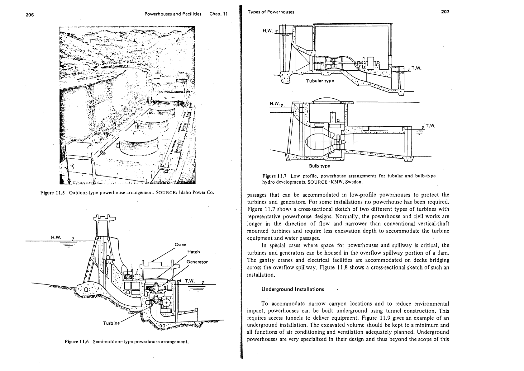
Figure
11.6
Semi-outdoor-type powerhouse arrangement.
Bulb
type
Figure
11.7
Low profile, powerhouse arrangements for tubular and bulb-type
hydro developments. SOURCE
:
KMW,
Sweden.
passages that can be accommodated in low-profile powerhouses to protect the
turbines and generators. For some installations no powerhouse has been required.
Figure
11.7
shows a cross-sectional sketch of two different types of turbines with
representative powerhouse designs. Normally, the powerhouse and civil works are
longer in the direction of flow and narrower than conventional vertical-shaft
mounted turbines and require less excavation depth to accommodate the turbine
equipment and water passages.
In special cases where space for powerhouses and spillway is critical, the
turbines and generators can be housed in the overflow spillway portion of a dam.
The gantry cranes and electrical facilities are accommodated on decks bridging
across the overflow spillway. Figure 11.8 shows a cross-sectional sketch of such
an
installation.
Underground Installations
a
To accommodate narrow canyon locations and to reduce environmental
impact, powerhouses can be built underground using tunnel construction. This
requires access tunnels to deliver equipment. Figure 11.9 gives
an
example of an
underground installation. The excavated volume should be kept to a
minimum and
all functions of air conditioning and ventilation adequately planned. Underground
powerhouses are very specialized in their design and thus beyond the scope of
this