Tsoulfanidis N. Measurement and detection of radiation
Подождите немного. Документ загружается.

338
MEASUREMENT
AND
DETECTION OF RADIATION
n
3102
H.V.
2015A
SCA
Amp/
.
TSCA
1
1446
2007 Universal
-
r
coincidence
802-4 constant start
2043
Nal(TI)
fraction
-
discr.
analyzer SCA
1
J
Out
timing delay
Logic
shaper
ADC
gate
Preamp
Delay
input
3105
H.V.
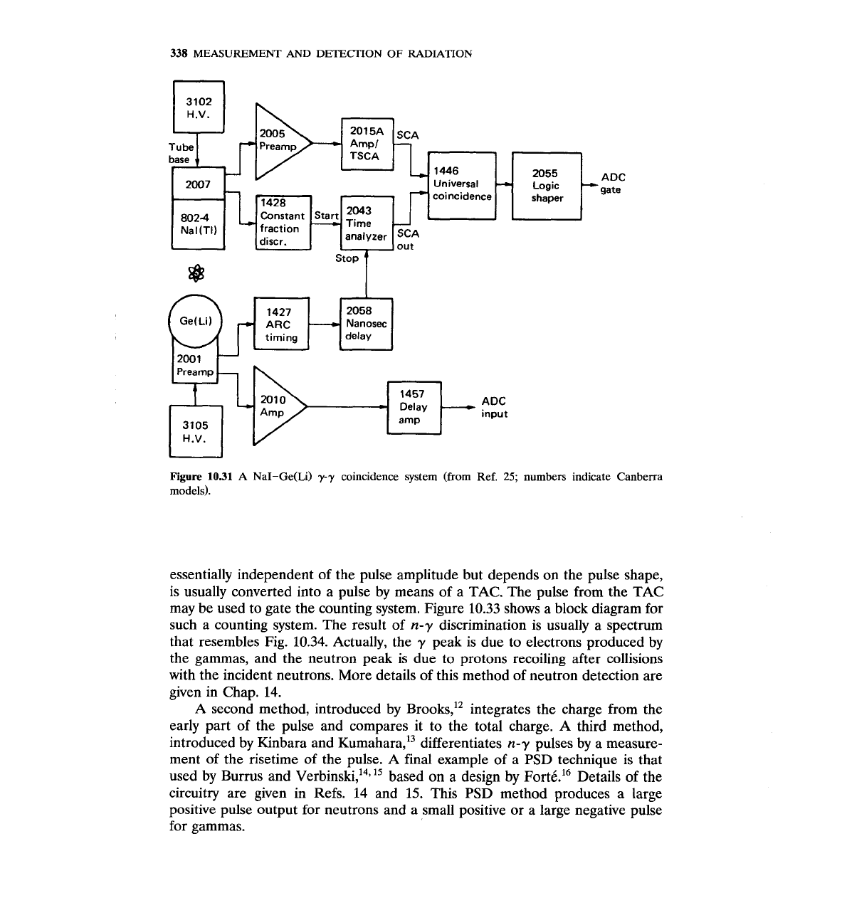
Figure
10.31
A
NaI-Ge(Li)
yy
coincidence system (from Ref.
25;
numbers indicate Canberra
models).
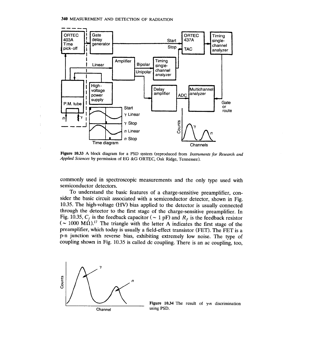
essentially independent of the pulse amplitude but depends on the pulse shape,
is usually converted into a pulse by means of a TAC. The pulse from the TAC
may be used to gate the counting system. Figure
10.33
shows a block diagram for
such a counting system. The result of
n-y
discrimination is usually
a
spectrum
that resembles Fig.
10.34.
Actually, the
y
peak is due to electrons produced by
the gammas, and the neutron peak is due to protons recoiling after collisions
with the incident neutrons. More details of this method of neutron detection are
given in Chap.
14.
A second method, introduced by ~rooks," integrates the charge from the
early part of the pulse and compares it to the total charge.
A
third method,
introduced by Kinbara and ~umahara,'~ differentiates
n-y
pulses by
a
measure-
ment of the risetime of the pulse.
A
final example of a
PSD
technique is that
used by Burrus and ~erbinski,'~,'~ based on a design by
FortC.16
Details
of
the
circuitry are given in Refs.
14
and
15.
This
PSD
method produces a large
positive pulse output for neutrons and a small positive or a large negative pulse
for gammas.
ELECTRONICS
339
I
Stilbene
Stilbene
1-
100 200 300 400
0-
100 200 300 400
Time,
ns
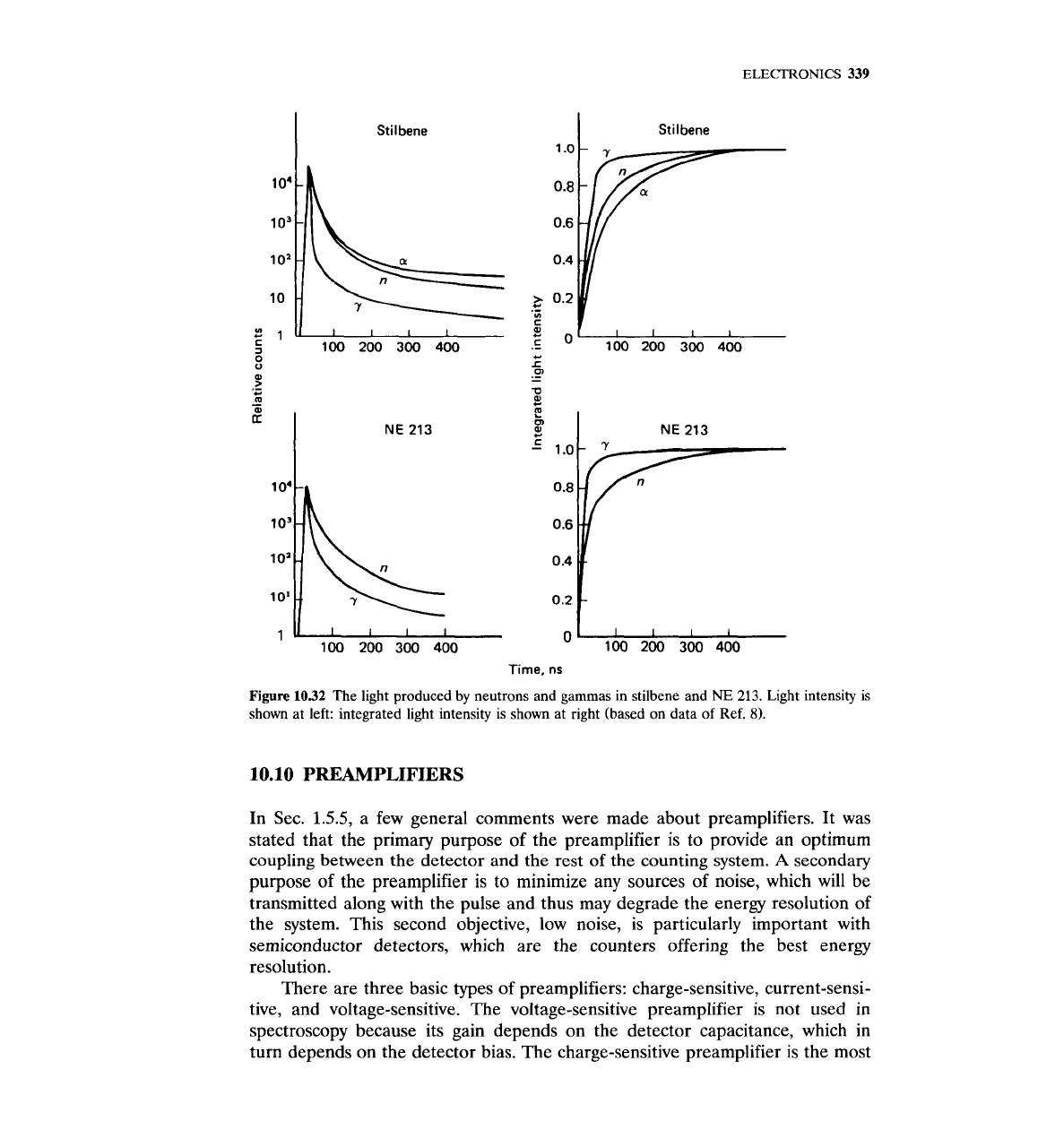
Figure
1032
The light produced by neutrons and gammas in stilbene and
NE
213.
Light intensity is
shown at left: integrated light intensity is shown at right (based on data of Ref.
8).
10.10
PREAMPLIFIERS
In Sec.
1.5.5,
a few general comments were made about preamplifiers. It was
stated that the primary purpose of the preamplifier is to provide an optimum
coupling between the detector and the rest of the counting system.
A
secondary
purpose of the preamplifier is to minimize any sources of noise, which will be
transmitted along with the pulse and thus may degrade the energy resolution of
the system. This second objective, low noise, is particularly important with
semiconductor detectors, which are the counters offering the best energy
resolution.
There are three basic types of preamplifiers: charge-sensitive,
current-sensi-
tive, and voltage-sensitive. The voltage-sensitive preamplifier is not used in
spectroscopy because its gain depends on the detector capacitance, which in
turn depends on the detector bias. The charge-sensitive preamplifier is the most
340
MEASUREMENT
AND
DETECTION OF RADIATION
I
"
stop
Time diagram
I
I
::"
route
Channels
Figure
10.33
A
block diagram for a PSD system (reproduced from
Instruments
for
Research and
Applied Sciences
by permission of
EG
&G
ORTEC, Oak Ridge, Tennessee).
commonly used in spectroscopic measurements and the only type used with
semiconductor detectors.
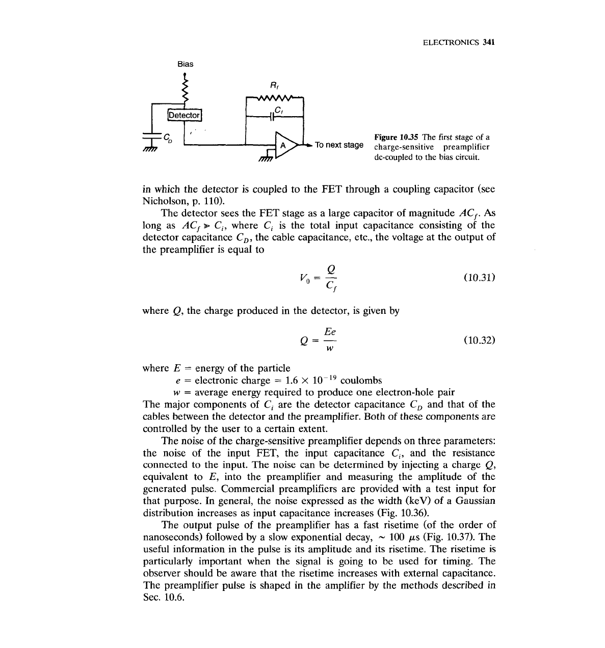
To understand the basic features of a charge-sensitive preamplifier, con-
sider the basic circuit associated with a semiconductor detector, shown in Fig.
10.35. The high-voltage
(HV)
bias applied to the detector is usually connected
through the detector to the first stage of the charge-sensitive preamplifier. In
Fig. 10.35,
Cf
is the feedback capacitor
(-
1
pF) and
Rf
is the feedback resistor
(-
1000
MR)."
The triangle with the letter
A
indicates the first stage of the
preamplifier, which today is usually a field-effect transistor (FET). The FET is a
p-n junction with reverse bias, exhibiting extremely low noise. The type of
coupling shown in Fig. 10.35 is called dc coupling. There is an ac coupling, too,
Channel
Figure
10.34
The result of
y-n
using PSD.
discrimination
ELECTRONICS
341
Bias
in which the detector is coupled to the FET through a coupling capacitor (see
Nicholson, p. 110).
The detector sees the FET stage as a large capacitor of magnitude
ACf.
As
long as
ACf
+
Ci,
where
Ci
is the total input capacitance consisting of the
detector capacitance
C,,
the cable capacitance, etc., the voltage at the output of
the preamplifier is equal to
f
where
Q,
the charge produced in the detector, is given by
Detector
.
,
where
E
=
energy of the particle
e
=
electronic charge
=
1.6
x
10~'~ coulombs
w
=
average energy required to produce one electron-hole pair
The major components of
Ci
are the detector capacitance
C,
and that of the
cables between the detector and the preamplifier. Both of these components are
controlled by the user to a certain extent.
The noise of the charge-sensitive preamplifier depends on three parameters:
the noise of the input FET, the input capacitance
Ci,
and the resistance
connected to the input. The noise can be determined by injecting
a
charge
Q,
equivalent to
E,
into the preamplifier and measuring the amplitude of the
generated pulse. Commercial preamplifiers are provided with a test input for
that purpose. In general, the noise expressed as the width (keV) of
a
Gaussian
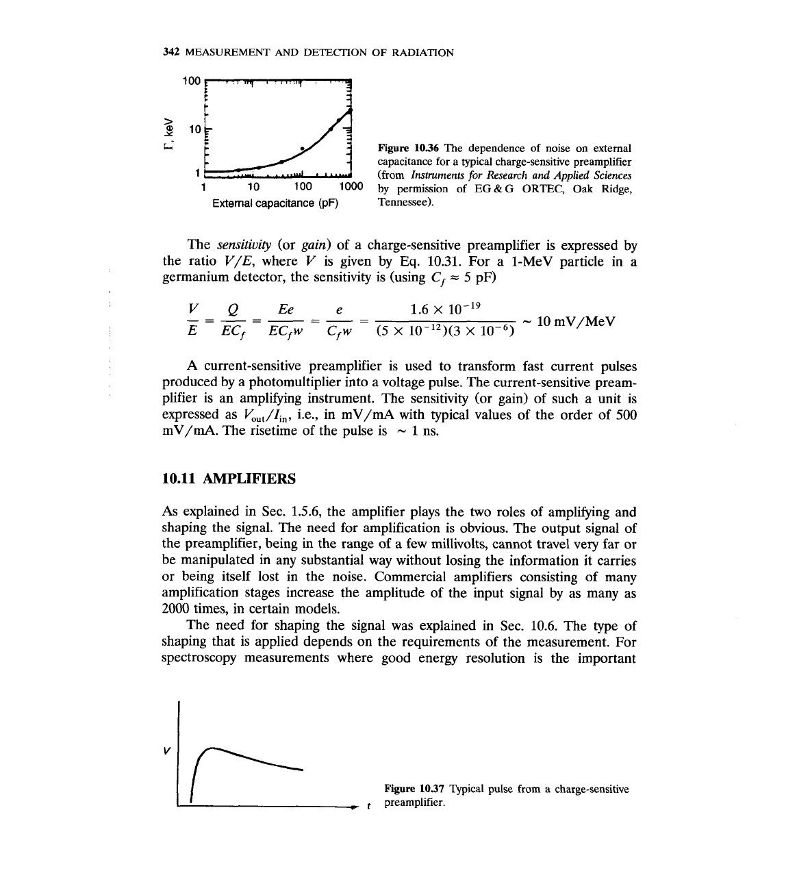
distribution increases as input capacitance increases (Fig. 10.36).
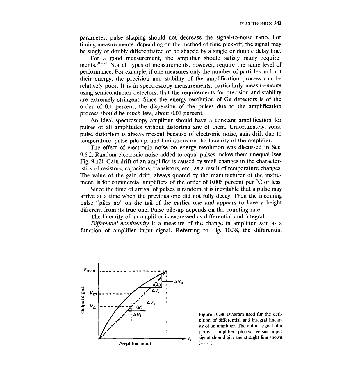
The
output pulse of the preamplifier has a fast risetime (of the order of
nanoseconds) followed by a slow exponential decay,
-
100 ps (Fig. 10.37). The
useful information in the pulse is its amplitude and its risetime. The risetime is
particularly important when the signal is going to be used for timing. The
observer should be aware that the risetime increases with external capacitance.
The preamplifier pulse is shaped in the amplifier by the methods described in
Sec. 10.6.
,pf
I I
Figure
1035
The first stage of a
To stage
charge-sensitive preamplifier
dc-coupled to the bias circuit.
342
MEASUREMENT
AND
DETECTION
OF
RADIATION
Y
i
Figure
1036
The dependence of noise on external
capacitance for a typical charge-sensitive preamplifier
1
=
l0U
1
10 100 1000
(from
by
permission
Instruments
of
for
EG
Research
&
G
ORTEC,
and
Applied
Oak
Sciences
Ridge,
External capacitance (pF)
Tennessee).
The
sensitivity
(or
gain)
of a charge-sensitive preamplifier is expressed by
the ratio V/E, where V is given by
Eq.
10.31. For a 1-MeV particle in a
germanium detector, the sensitivity is (using
Cf
-
5 pF)
A
current-sensitive preamplifier is used to transform fast current pulses
produced by a photomultiplier into a voltage pulse. The current-sensitive pream-
plifier is an amplifying instrument. The sensitivity (or gain) of such a unit is
expressed as
V,,,/Zi,,
i.e., in mV/mA with typical values of the order of 500
mV/mA. The risetime of the pulse is
-
1
ns.
10.11
AMPLIFIERS
As explained in Sec. 1.5.6, the amplifier plays the two roles of amplifying and
shaping the signal. The need for amplification is obvious. The output signal of
the preamplifier, being in the range of a few millivolts, cannot travel very far or
be manipulated in any substantial way without losing the information it carries
or being itself lost in the noise. Commercial amplifiers consisting of many
amplification stages increase the amplitude of the input signal by as many as
2000 times, in certain models.
The need for shaping the signal was explained in
Sec. 10.6. The type of
shaping that is applied depends on the requirements of the measurement. For
spectroscopy measurements where good energy resolution is the important
I
Figure
1037
Typical
pulse from a charge-sensitive
preamplifier.
ELECTRONICS
343
parameter, pulse shaping should not decrease the signal-to-noise ratio. For
timing measurements, depending on the method of time pick-off, the signal may
be singly or doubly differentiated or be shaped by a single or double delay line.
For a good measurement, the amplifier should satisfy many require-
ment~.'~-~~ Not all types of measurements, however, require the same level of
performance. For example, if one measures only the number of particles and not
their energy, the precision and stability of the amplification process can be
relatively poor. It is in spectroscopy measurements, particularly measurements
using semiconductor detectors, that the requirements for precision and stability
are extremely stringent. Since the energy resolution of Ge detectors is of the
order of 0.1 percent, the dispersion of the pulses due to the amplification
process should be much less, about 0.01 percent.
An
ideal spectroscopy amplifier should have a constant amplification for
pulses of all amplitudes without distorting any of them. Unfortunately, some
pulse distortion is always present because of electronic noise, gain drift due to
temperature, pulse pile-up, and limitations on the linearity of the amplifier.
The effect of electronic noise on energy resolution was discussed in Sec.
9.6.2. Random electronic noise added to equal pulses makes them unequal (see
Fig. 9.12). Gain drift of an amplifier is caused by small changes in the character-
istics of resistors, capacitors, transistors, etc., as a result of temperature changes.
The value of the gain drift, always quoted by the manufacturer of the instru-
ment, is for commercial amplifiers of the order of 0.005 percent per
"C
or less.
Since the time of arrival of pulses is random, it is inevitable that a pulse may
arrive at a time when the previous one did not fully decay. Then the incoming
pulse "piles up" on the tail of the earlier one and appears to have a height
different from its true one. Pulse pile-up depends on the counting rate.
The linearity of an amplifier is expressed as differential and integral.
Differential nonlinearity
is a measure of the change in amplifier gain as a
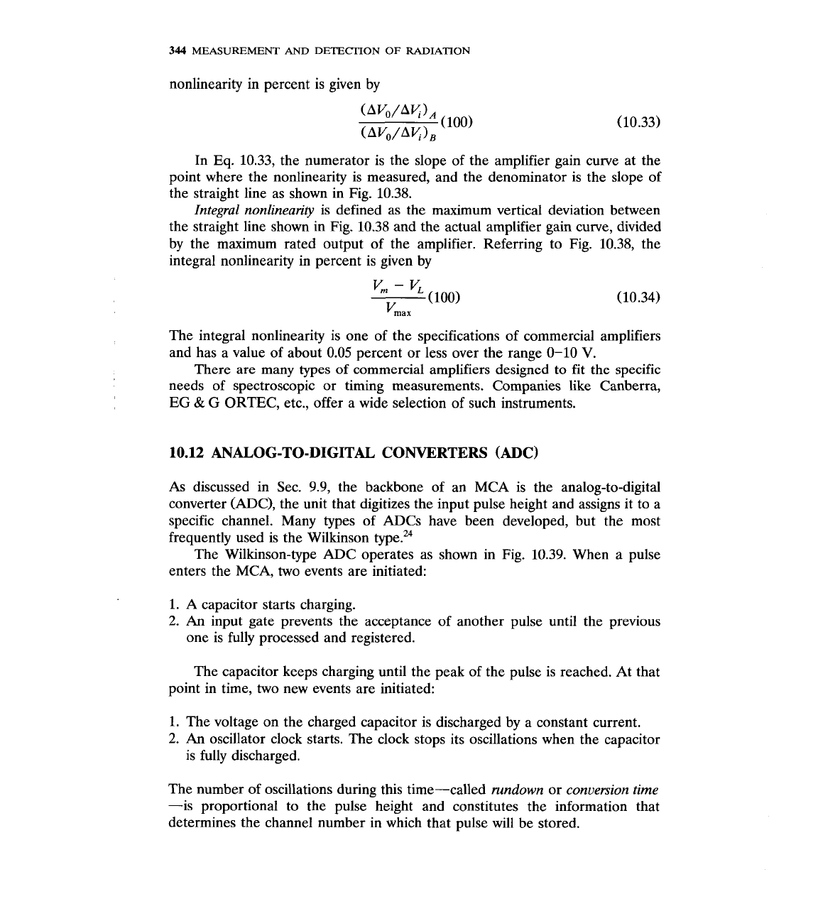
function of amplifier input signal. Referring to Fig.
10.38,
the differential
Figure
10.38
Diagram used for
the
defi-
nition
of
differential and integral linear-
ity of an amplifier.
The
output signal of a
perfect amplifier plotted versus input
signal should give the straight line shown
Amplifier input
(-.-.-.
),
344
MEASUREMENT
AND
DETECTION
OF
RADIATION
nonlinearity in percent is given by
In Eq. 10.33, the numerator is the slope of the amplifier gain curve at the
point where the nonlinearity is measured, and the denominator is the slope of
the straight line as shown in Fig. 10.38.
Integral nonlinearity
is defined as the maximum vertical deviation between
the straight line shown in Fig. 10.38 and the actual amplifier gain curve, divided
by the maximum rated output of the amplifier. Referring to Fig. 10.38, the
integral nonlinearity in percent is given by
The integral nonlinearity is one of the specifications of commercial amplifiers
and has a value of about 0.05 percent or less over the range 0-10
V.
There are many types
of
commercial amplifiers designed to fit the specific
needs of spectroscopic or timing measurements. Companies like Canberra,
EG
&
G ORTEC, etc., offer a wide selection of such instruments.
10.12
ANALOG-TO-DIGITAL CONVERTERS (ADC)
As discussed in Sec. 9.9, the backbone of an MCA is the analog-to-digital
converter (ADC), the unit that digitizes the input pulse height and assigns it to a
specific channel. Many types of ADCs have been developed, but the most
frequently used is the Wilkinson
type.24
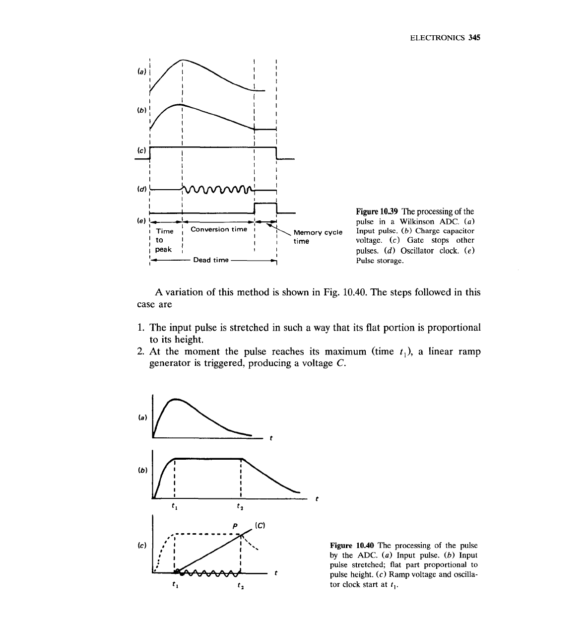
The Wilkinson-type ADC operates as shown in Fig. 10.39. When a pulse
enters the MCA, two events are initiated:
1. A capacitor starts charging.
2.
An
input gate prevents the acceptance of another pulse until the previous
one is fully processed and registered.
The capacitor keeps charging until the peak of the pulse is reached. At that
point in time, two new events are initiated:
1.
The voltage on the charged capacitor is discharged by a constant current.
2.
An
oscillator clock starts. The clock stops its oscillations when the capacitor
is fully discharged.
The number of oscillations during this time-called
rundown
or
conversion time
-is proportional to the pulse height and constitutes the information that
determines the channel number in which that pulse will be stored.
I
I
I
I
I
I
I
I
Figure
1039
The processing of the
pulse in a Wilkinson ADC.
(a)
emery
cycle
Input pulse.
(b)
Charge capacitor
voltage.
(c)
Gate stops other
I
I
pulses.
(d)
Oscillator clock.
(e)
I-
Dead time
-<
Pulse storage.
A
variation of this method is shown in Fig.
10.40.
The steps followed in this
case are
1.
The input pulse is stretched in such a way that its flat portion is proportional
to its height.
2.
At the moment the pulse reaches its maximum (time
t,),
a linear ramp
generator is triggered, producing
a
voltage
C.
Figure
10.40
The processing of the pulse
by
the
ADC.
(a)
Input pulse.
(b)
Input
pulse stretched; flat part proportional to
pulse height.
(c)
Ramp voltage and oscilla-
tor clock start at
1,.
346
MEASUREMENT
AND
DETECTION
OF
RADIATION
3. At the same moment (t,), a gate signal is produced and an oscillator clock is
turned on.
When the voltage ramp signal reaches the flat part of the stretched pulse
(PI,
the gate signal turns the clock off. Thus, the time interval (t,
-
t,) and,
therefore, the number of oscillations during (t,
-
t,) are again proportional to
the height of the pulse. This second method of ADC operation (Fig. 10.40) is not
favored because it is difficult to keep the pulse height constant for the time
interval (t,
-
t,).
Figure 10.39 shows, in addition to the principle of operation of the Wilkin-
son ADC, the reason for the dependence of the MCA dead time on the channel
number. The dead time consists of three components:
1.
Pulse risetime
2. Conversion time
3. Memory cycle time (time it takes to store the digitized signal)
Of the three components, the second is the most important because it depends
on the channel number. One can reduce the size of the conversion time by using
a clock with higher frequency. Today's ADCs use quartz-stabilized clocks with a
,
frequency of
up
to
450
MHz.
Obviously, for a Wilkinson
ADC,
the higher the
clock frequency is, the shorter the dead time will be. The equation for dead time
is written as
where a typical value of
a,
is 1.5 ps,
C
=
address (channel) count, and
X
=
effective digital offset." The digital offset is a capability offered by modern
ADCs of subtracting a certain number of channels from the converted channel
number before the data are introduced into the memory. One application of
digital offset is to enhance resolution in a measurement performed with a small
MCA. For example, with a 1000-channel MCA and an 8000 channel ADC, a
7000 digital offset allows data to be recorded for the top eighth of the spectrum
only. A fixed dead time
(FDT)
ADC has also been developed for certain
application^.^^
The resolution of an ADC is expressed in terms of channels. It represents
the maximum number of discrete voltage increments into which the maximum
input pulse can be subdivided. ADC resolutions range from 4096 to 16,384
channels. Since commercial amplifiers can provide a maximum 10-V pulse, an
ADC with a resolution of 4096 channels may subdivide 10
V
into 4096 incre-
ments. Another quantity used is the conversion gain of the ADC. The conver-
sion gain may be considered as a subset of the resolution.
An
ADC with a
resolution of 16,384 channels may be used, depending on the application, with a
conversion gain of 4096, or 8192, or 16,384 channels.
The accuracy of the ADC is expressed in terms of its differential and
integral nonlinearity. The differential nonlinearity describes the uniformity of
address widths over the entire range of the ADC. To make this point better

ELECTRONICS
347
understood, assume that a 1000-channel ADC is used to process pulses with
maximum height of 10
V.
Then the average address width is
10/1000
=
lOmV/channel. The ideal ADC should provide a conversion of 10 mV/channel
at any channel. Any deviation between this width and the actual one is
expressed by the differential nonlinearity. Mathematically, if
-
AV
=
average width
AVmax
=
maximum width
AVmin
=
minimum width
then the differential nonlinearity is given by the equation
%
Differential nonlinearity
=
AVmax
-
Avmin
-
(100)
(10.36)
AV
Commercial ADCs have differential nonlinearity of the order of
k
0.5 percent
to
S
1
percent.
The
integral nonlinearity
is defined as the maximum deviation of any address
(ADC channel) from its nominal position, determined by a linear plot of address
(ADC channel) versus input pulse amplitude (Fig. 10.41). The maximum pulse
height
VmaX
corresponds to the maximum address
N,,,.
If
N
is the address
number with the maximum deviation between the actual and nominal pulse
heights, the integral nonlinearity is given by the equation
Vnom
-
Kc,
%
Integral nonlinearity
=
(100) (10.37)
vmax
Modern commercial ADCs have integral nonlinearity of the order of
f
0.05
percent over
98-99
percent of the full range.
The integral nonlinearity affects the centroid position of energy peaks,
which in turn affects the calibration of the system as well as the identification of
unknown energy peaks.
10.13
MULTIPARAMETER ANALYZERS
The MCA is an instrument that stores events by a single parameter, namely,
pulse height. When the need arises, however, there are many experiments for
I
I
n
ADC
channel
Figure
10.41
The definition
of
integral nonlinearity is based on a linear plot of
ADC
channel versus
pulse amplitude.