Tsoulfanidis N. Measurement and detection of radiation
Подождите немного. Документ загружается.

318
MEASUREMENT
AND
DETECTION
OF
RADIATION
The resistance
R
is a measure of how difficult (or easy) it is for an electric
current to flow through a conductor. The resistance is defined by Ohm's law as
the ratio of a voltage to current flowing through a conductor (Fig.
10.1~). The
resistance is measured in ohms
(a). If a potential difference of
1
V generates a
current of
1
A, the resistance is
1
a; that is,
Capacitance C is the ability to store electrical charge.
A
capacitor usually
consists of two conductors separated
by
an insulator or a dielectric (Fig. 10.lb).
Every conductor, e.g., simple metal wire, has a certain capacitance. The capaci-
tance is measured in farads (F). If a charge of
1
coulomb produces
a
potential
difference of
1
V between the two conductors forming the capacitor, then its
capacitance is
1
F; that is,
9
c=- (10.2)
v
If the voltage across the capacitor is constant, no current flows through it; i.e., a
capacitor acts as an open circuit to dc voltage. If, however, the voltage changes,
a current flows through the capacitor equal to
Inductance refers to the property of conductors to try to resist a change in a
magnetic field. If the current flowing through a conductor changes with time (in
which case the magnetic field produced
by
the current also changes), a potential
difference is induced that opposes the change. The induced potential difference
VL
is given
by
(Fig. 10.1~)
where
L
is called the inductance of the conductor and is measured in henrys
(H).
If a current change of
1
A/s induces a potential difference of
1
V, the
inductance is
1
H.
An
inductor is usually indicated as a coil (Fig. lO.lc), but any
(a)
(b)
--
(c)
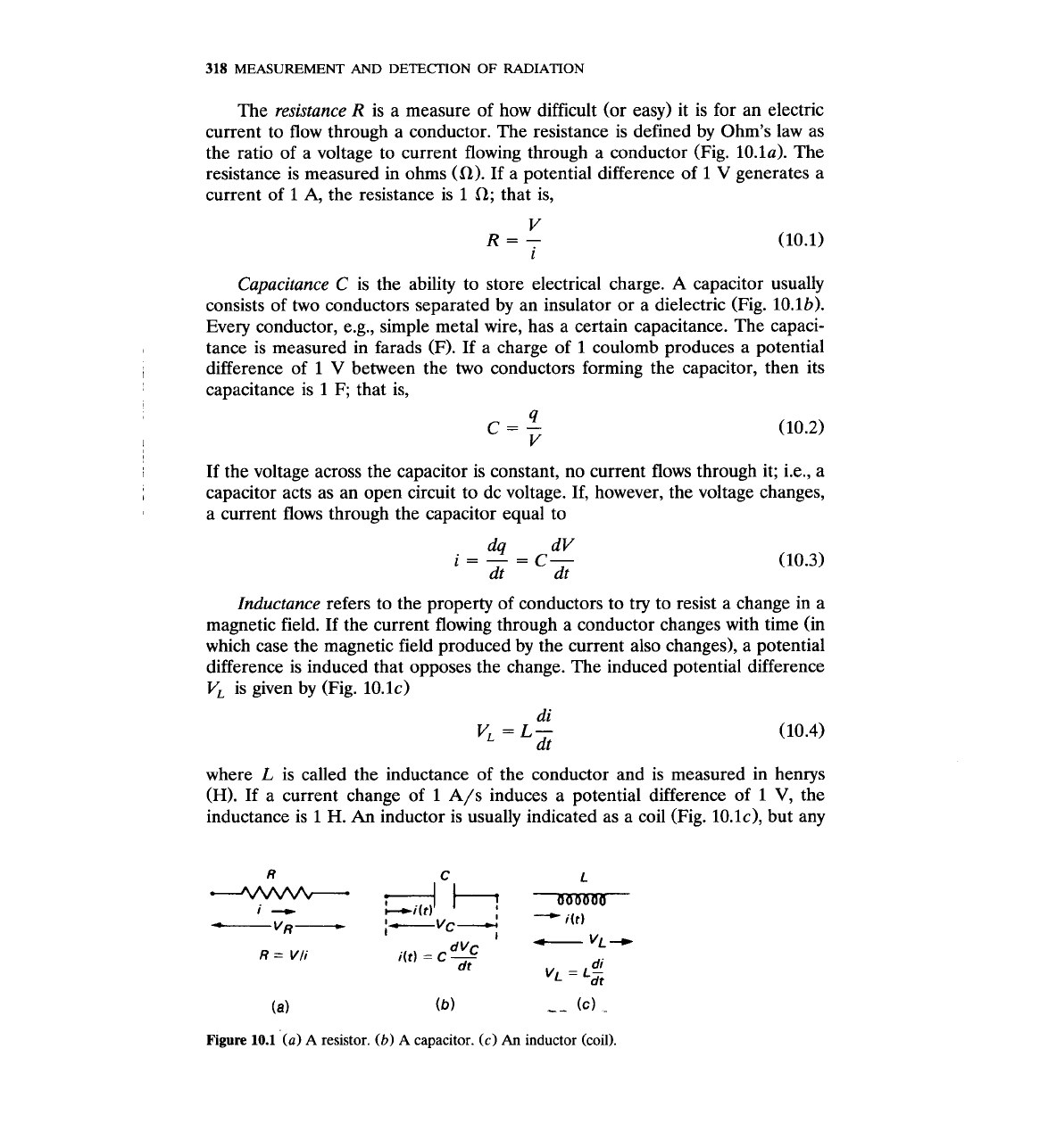
Figure
10.1
(a)
A
resistor.
(b)
A
capacitor.
(c)
An
inductor (coil).
conductor, e.g., a metal wire, has a certain inductance. No pure inductor exists
because there is always some ohmic resistance and some capacitance in the
wires making the coils.
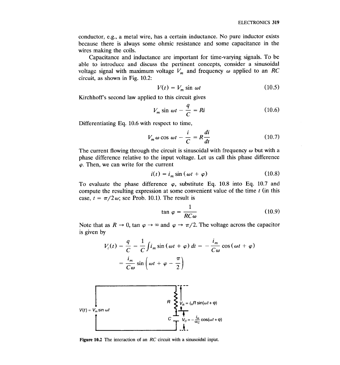
Capacitance and inductance are important for time-varying signals. To be
able to introduce and discuss the pertinent concepts, consider a sinusoidal
voltage signal with maximum voltage
Vm
and frequency
w
applied to an
RC
circuit, as shown in Fig.
10.2:
V(t)
=
Vm
sin
wt
(10.5)
Kirchhoff's second law applied to this circuit gives
9
Vm
sin
wt
-
-
=
Ri
(10.6)
C
Differentiating Eq.
10.6
with respect to time,
The current flowing through the circuit is sinusoidal with frequency
w
but with a
phase difference relative to the input voltage. Let us call this phase difference
cp.
Then, we can write for the current
i(t)
=
im
sin
(wt
+
cp)
(10.8)
To evaluate the phase difference
cp,
substitute Eq.
10.8
into Eq.
10.7
and
compute the resulting expression at some convenient value of the time
t
(in this
case,
t
=
7r/2w;
see Prob.
10.1).
The result is
1
tan
cp
=
-
RCw
Note that as
R
+
0,
tan
cp
+
and
cp
+
r/2.
The voltage across the capacitor
is given by
Figure
10.2
The interaction of an
RC
circuit with a sinusoidal input.
320
MEASUREMENT
AND
DETECTION
OF
RADIATION
At every time
t,
the instantaneous potentials
V(t), VR(t),
and
Vc(t)
satisfy
the equation
v(t)
=
vR(t>
+
vc(t)
(10.10)
The peak potentials, however, are not additive linearly because their maxima do
not occur at the same time. To find the correct relationship, apply Eq.
10.7
at
time
t
=
-(cp/w)
with
i(t)
from
Eq.
10.8.
The result is
vm
vm
1
cos
cp
=
-
- -
Vm
lm
=
-
R
(10.11)
R
,I-
,IR'
+
(1/02C2)
Equation
10.11
is the analog of Ohm's law for the
RC
circuit. The "resistance7'
of the circuit is called the impedance Z and is given by
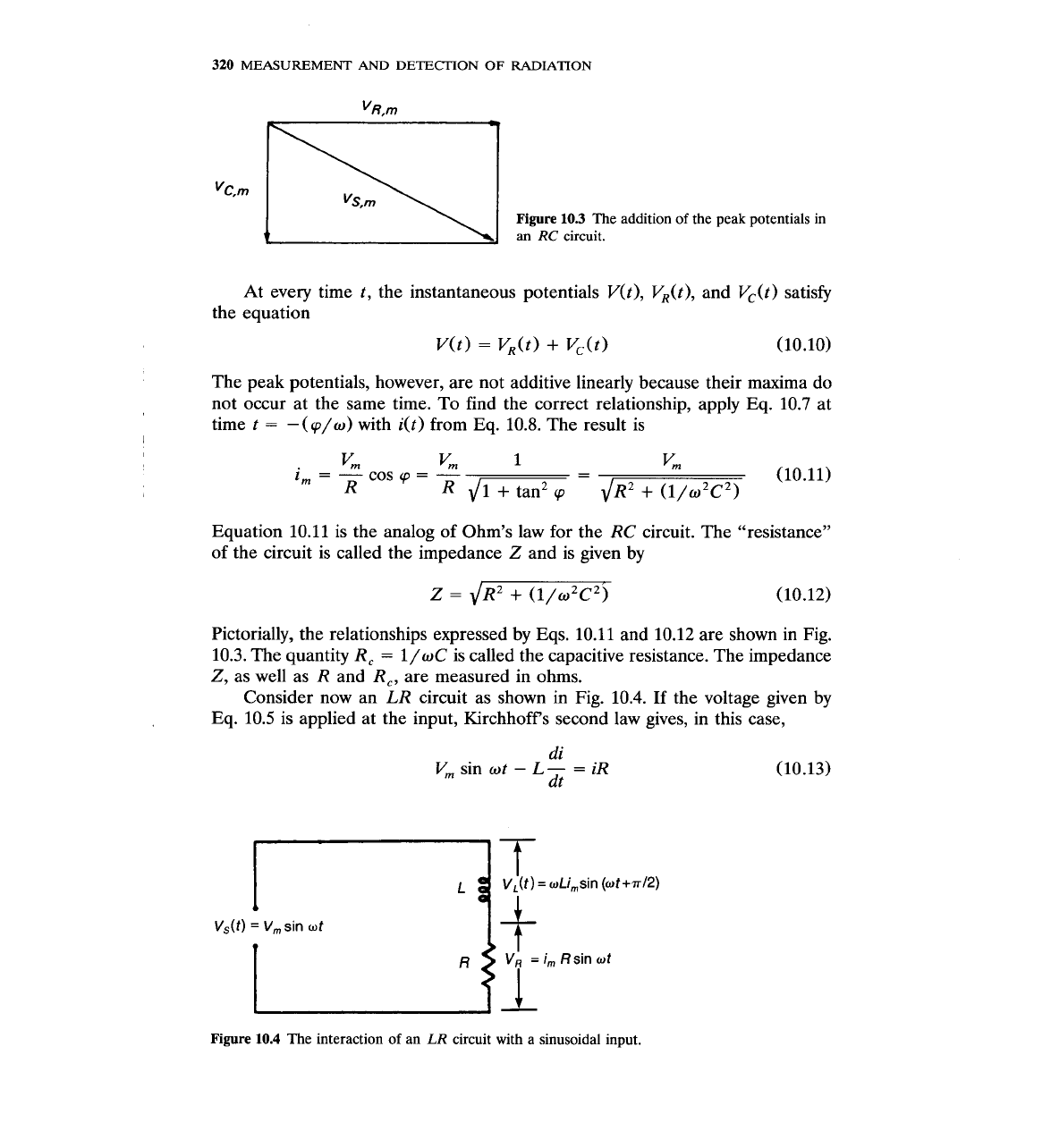
Pictorially, the relationships expressed by Eqs.
10.11
and
10.12
are shown in Fig.
10.3.
The quantity
R,
=
l/wC
is called the capacitive resistance. The impedance
Z, as well as
R
and
R,,
are measured in ohms.
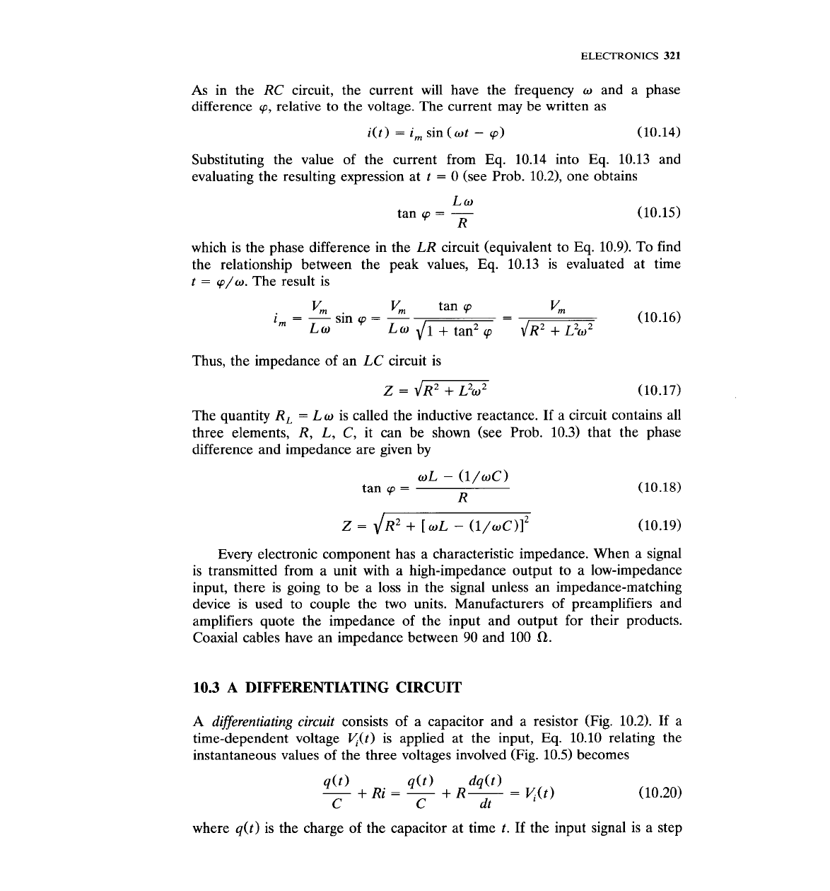
Consider now an
LR
circuit as shown in Fig.
10.4.
If the voltage given by
Eq.
10.5
is applied at the input, Kirchhoffs second law gives, in this case,
di
Vm
sin
ot
-
L-
=
iR
dt
(10.13)
Figure
10.4
The interaction of an
LR
circuit with a sinusoidal input.
ELECTRONICS
321
As in the
RC
circuit, the current will have the frequency
o
and a phase
difference
cp,
relative to the voltage. The current may be written as
i(t)
=
i,
sin
(ot
-
cp)
(10.14)
Substituting the value of the current from Eq.
10.14
into Eq.
10.13
and
evaluating the resulting expression at
t
=
0
(see Prob.
10.2),
one obtains
Lo
tan
cp
=
-
R
which is the phase difference in the
LR
circuit (equivalent to Eq.
10.9).
To find
the relationship between the peak values, Eq.
10.13
is evaluated at time
t
=
cp/w.
The result is
Thus, the impedance of an
LC
circuit is
The quantity
R,
=
Lo
is called the inductive reactance.
If
a circuit contains all
three elements,
R, L, C,
it can be shown (see Prob.
10.3)
that the phase
difference and impedance are given by
oL
-
(l/wC)
tan
cp
=
R
Every electronic component has a characteristic impedance. When a signal
is transmitted from a unit with a high-impedance output to a low-impedance
input, there is going to be a loss in the signal unless an impedance-matching
device is used to couple the two units. Manufacturers of preamplifiers and
amplifiers quote the impedance of the input and output for their products.
Coaxial cables have an impedance between
90
and
100
a.
10.3
A
DIFFERENTIATING CIRCUIT
A
differentiating circuit
consists of a capacitor and a resistor (Fig.
10.2).
If a
time-dependent voltage
T/l(t)
is applied at the input, Eq.
10.10
relating the
instantaneous values of the three voltages involved (Fig.
10.5)
becomes
where q(t) is the charge of the capacitor at time t. If the input signal is a step
322
MEASUREMENT
AND DETECIION OF RADIATION
I
1
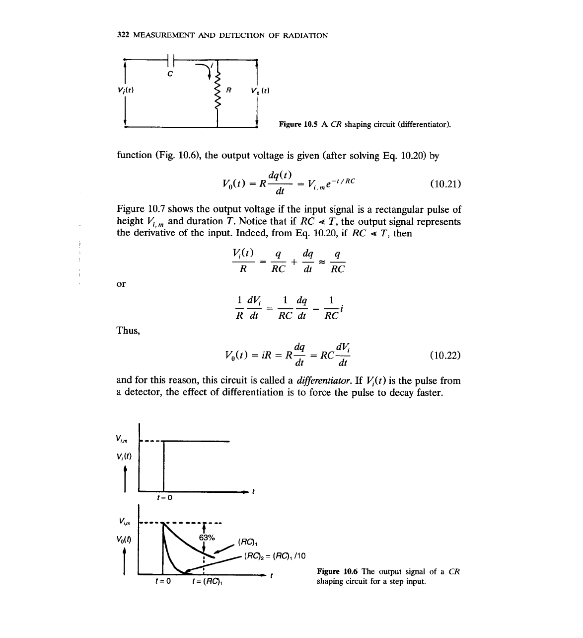
Figure
10.5
A
CR
shaping circuit (differentiator).
function (Fig. 10.6), the output voltage is given (after solving
Eq.
10.20)
by
Figure 10.7 shows the output voltage if the input signal is a rectangular pulse of
height
v,,
and duration
T.
Notice that if
RC
4
T,
the output signal represents
the derivative of the input. Indeed, from
Eq.
10.20, if
RC
4
T,
then
Thus,
and for this reason, this circuit is called a differentiator. If
K(t) is the pulse from
a detector, the effect of differentiation is to force the pulse to decay faster.
Figure
10.6
The output signal of a
CR
t=O
t=(RQ,
shaping circuit for
a
step input.

ELECTRONICS
323
I
rectangular pulse.
As shown in Sec.
10.2,
for a sinusoidal signal the peak value of the potential
across the resistor of an
RC
circuit is related to the peak of the input signal by
where
o
=
27~f
and
f
is the frequency of input signal. According to Eq.
10.23,
as the frequency decreases, the fraction of the signal appearing at the output of
the differentiator also decreases, approaching zero for very low frequencies. For
this reason, this circuit is called a
high-pass filter.
The output of the filter as a
function of frequency is shown in Fig.
10.8.
If the signal is not purely sinusoidal,
it may be decomposed into
a
series of sine components with frequencies that are
multiples of a fundamental one (this is called Fourier analysis). Going through
0.01
I
I
Figure
10.8
The output of a differentia-
I
I
,
f/f,
tor (high-pass) filter as a function of
0.01
0.1 1
input frequency.
324
MEASUREMENT
AND
DETECTION
OF
RADIATION
.u
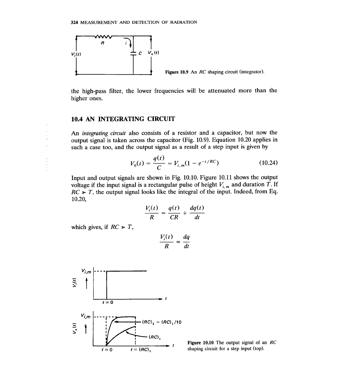
Figure
10.9
An
RC
shaping circuit (integrator).
the high-pass filter, the lower frequencies will be attenuated more than the
higher ones.
10.4
AN
INTEGRATING CIRCUIT
An
integrating circuit
also consists of a resistor and a capacitor, but now the
output signal is taken across the capacitor (Fig. 10.9). Equation 10.20 applies in
such a case too, and the output signal as a result of a step input is given by
Input and output signals are shown in Fig. 10.10. Figure 10.11 shows the output
voltage if the input signal is a rectangular pulse of height
K,,
and duration T.
If
RC
s
T,
the output signal looks like the integral of the input. Indeed, from Eq.
10.20,
which gives, if
RC
s
T,
p(RC),
=
(RC),/IO
P
t
Figure
10.10
The output signal of an
RC
t=0 t
=
(RC),
shaping circuit for
a
step input (top).
ELECTRONICS
325
;&
I
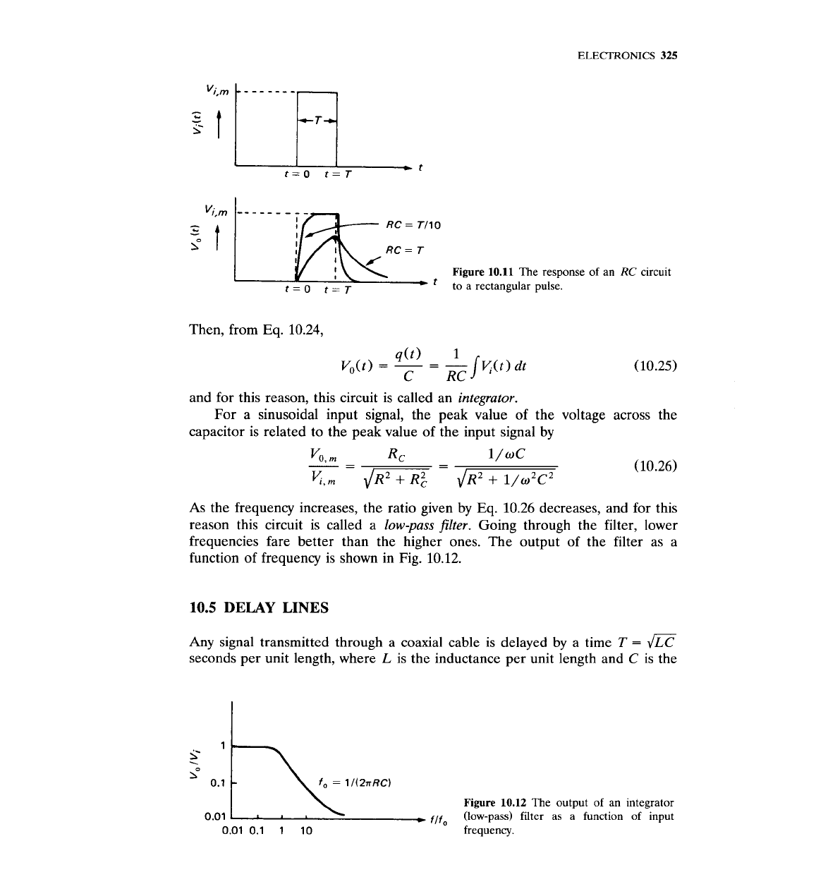
Figure
10.11
The response of an
RC
circuit
t=O t=~
*
to a rectangular pulse.
Then, from Eq. 10.24,
and for this reason, this circuit is called an
integrator.
For a sinusoidal input signal, the peak value of the voltage across the
capacitor is related to the peak value of the input signal by
As the frequency increases, the ratio given
by
Eq. 10.26 decreases, and for this
reason this circuit is called a
low-pass filter.
Going through the filter, lower
frequencies fare better than the higher ones. The output of the filter as a
function of frequency is shown in Fig. 10.12.
10.5
DELAY
LINES
Any signal transmitted through a coaxial cable is delayed by a time
T
=
seconds per unit length, where
L
is the inductance per unit length and
C
is the
2
.
lo
Figure
10.12
The output of an integrator
flf,
(low-pass) filter as a function of input
0.01 0.1
1
10
frequency.

326
MEASUREMENT
AND
DETECTION
OF
RADIATION
I
I
I
Time
I
I
Reflected signal
I
L
I
'~4
--
output signal
Time
Figure
10.13
The use of a delay line to
input output
form a rectangular pulse.
capacitance per unit length. For ordinary coaxial cables, the delay is about
5
ns/m. For larger delays, the central conductor of the cable is spiraled to
increase the inductance per unit length.
Commercial delay lines are a little more complicated than a simple cable.
They are used not only to delay a signal, but also to produce a rectangular pulse
for subsequent pulse shaping or for triggering another electronic unit (e.g., a
scaler). The formation of the rectangular pulse is achieved by reflecting the
delayed signal at the end of the delay line, bringing it back to the input and
adding it to the original signal (Fig. 10.13).
A
double delay line produces the
double rectangular pulse shown in Fig. 10.14.
10.6
PULSE
SHAPING
The pulse produced at the output of a radiation detector has to be modified or
shaped
for better performance of the counting system. There are three reasons
that necessitate pulse shaping:
1.
To
prevent overlap.
Each pulse should last for as short a period of time as
possible, and then its effect should be abolished so that the system may be
'
.
-T-
*2T&
Delay
]
line Delay line
input
%
output
Figure
10.14
The
effect of a double delay line.
ELECTRONICS
327
ready for the next pulse. Without pulse shaping, the detector signal lasts so
long that pulses overlap. If only the number of particles is counted, pulse
overlap leads to loss of counts (dead time loss). In spectroscopy measure-
ments, pulse overlap worsens the resolution.
2.
To improve the signal-to-noise ratio.
Noise created in the detector and the
early amplification stages accompanies the detector signal. Appropriate pulse
shaping can enhance the signal while at the same time reduce the noise.
Thus, the signal-to-noise ratio will improve, which in turn, leads to better
energy resolution.
3.
For special pulse manipulation.
The detector pulse may, in certain applica-
tions, need special pulse shaping to satisfy the needs of certain units of the
counting system. As an example, the signal at the output of the amplifier
needs to be stretched before it is recorded in the memory of a multichannel
analyzer (see Sec. 10.12).
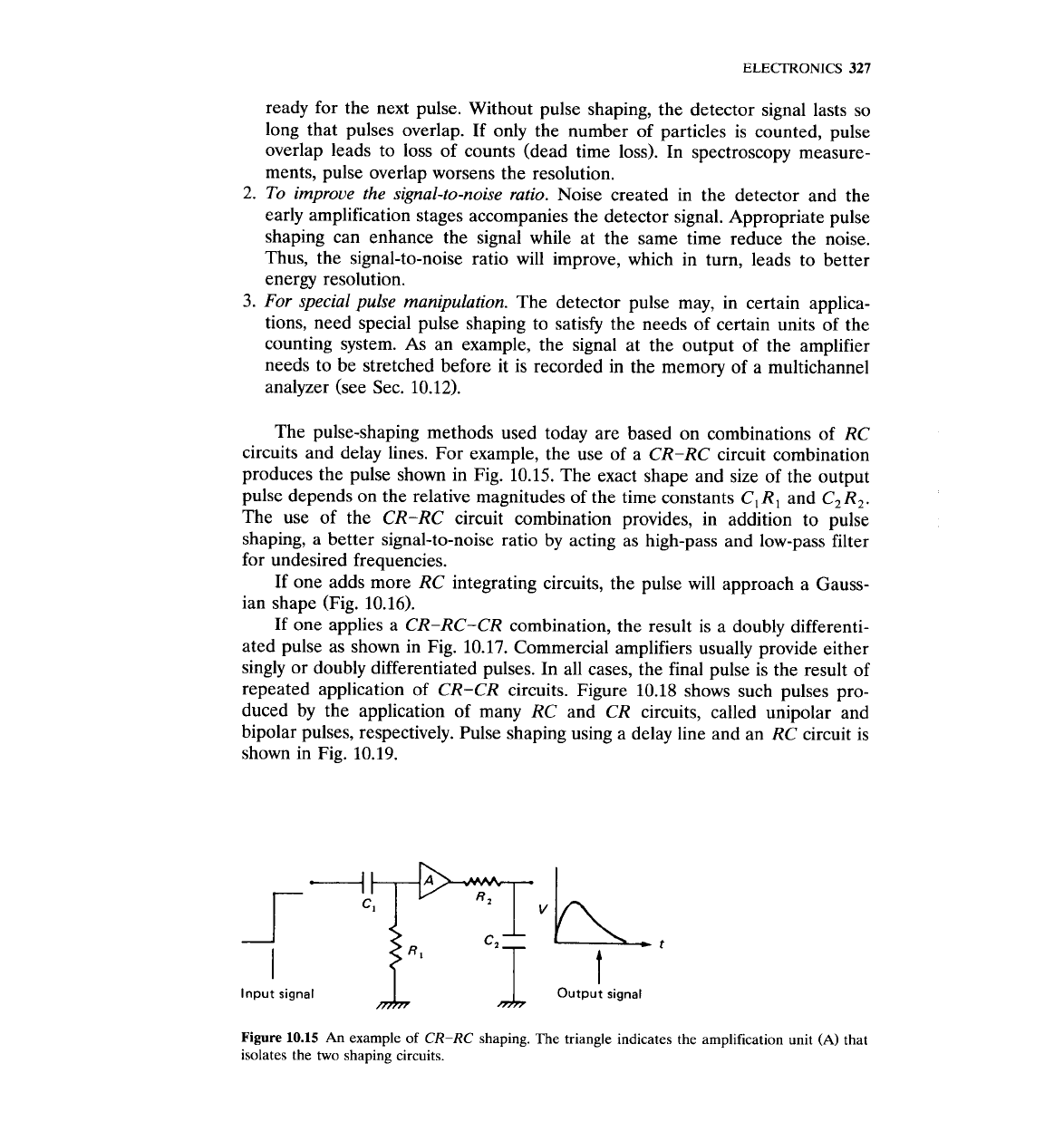
The pulse-shaping methods used today are based on combinations of
RC
circuits and delay lines. For example, the use of a
CR-RC
circuit combination
produces the pulse shown in Fig. 10.15. The exact shape and size of the output
pulse depends on the relative magnitudes of the time constants
C,
R,
and
C, R,.
The use of the
CR-RC
circuit combination provides, in addition to pulse
shaping, a better signal-to-noise ratio by acting as high-pass and low-pass filter
for undesired frequencies.
If one adds more
RC
integrating circuits, the pulse will approach a Gauss-
ian shape (Fig. 10.16).
If one applies a
CR-RC-CR
combination, the result is a doubly differenti-
ated pulse as shown in Fig. 10.17. Commercial amplifiers usually provide either
singly or doubly differentiated pulses. In all cases, the final pulse is the result of
repeated application of
CR-CR
circuits. Figure 10.18 shows such pulses pro-
duced by the application of many
RC
and
CR
circuits, called unipolar and
bipolar pulses, respectively. Pulse shaping using a delay line and an
RC
circuit is
shown in Fig. 10.19.
Input signal
A
~utpu; signal
Figure
10.15
An
example
of
CR-RC
shaping. The triangle indicates the amplification unit
(A)
that
isolates the
two
shaping circuits.